Graco SaniForce 1040e User Manual
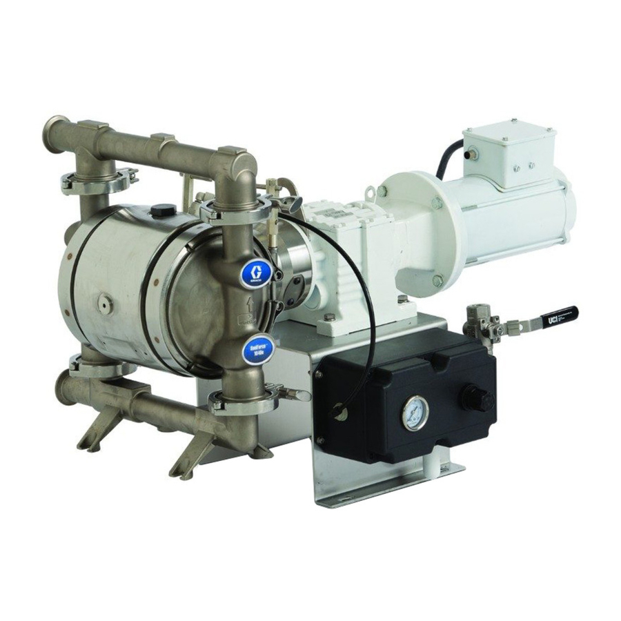
Electric-operated diaphragm pump
Hide thumbs
Also See for SaniForce 1040e:
- Operation (64 pages) ,
- Repair parts (40 pages) ,
- Repair parts (40 pages)
Table of Contents
Advertisement
Quick Links
Operation
SaniForce® 1040e
SaniForce®
SaniForce®
Diaphragm
Diaphragm
Diaphragm Pump
For fluid
fluid transfer
transfer in in in indoor
indoor sanitary
For
For
fluid
transfer
indoor
hazardous
hazardous
hazardous (classified)
(classified) locations
(classified)
professional
professional use
professional
use only.
use
only.
only.
Important Safety
Important
Important
Safety Instructions
Safety
Read all warnings and instructions in this manual before using the
Save these
equipment. Save
Save
For maximum operating pressures,
see the Performance Charts on pages
50–55.
See pages 6–8 for model information,
including approvals.
1040e Electric
Electric - - - Operated
1040e
Electric
Pump
Pump
sanitary applications.
applications. Not
sanitary
applications.
locations
locations unless
unless otherwise
unless
otherwise stated.
otherwise
Instructions
Instructions
these instructions.
instructions.
these
instructions.
PROVEN QUALITY. LEADING TECHNOLOGY.
Operated
Operated
Not approved
approved for
for use
use in in in explosive
Not
approved
for
use
stated. See
stated.
See approvals
See
approvals page
approvals
3A3167P
explosive atmospheres
atmospheres or or or
explosive
atmospheres
page for
page
for more
for
more information.
more
information. For
information.
EN
For
For
Advertisement
Table of Contents

Related Manuals for Graco SaniForce 1040e


Summary of Contents for Graco SaniForce 1040e
- Page 1 Operation SaniForce® 1040e 1040e Electric Electric - - - Operated Operated SaniForce® SaniForce® 1040e Electric Operated 3A3167P Diaphragm Diaphragm Diaphragm Pump Pump Pump For fluid fluid transfer transfer in in in indoor indoor sanitary sanitary applications. applications. Not Not approved approved for for use use in in in explosive...
-
Page 2: Table Of Contents
Lubrication........... 42 Wire Connections at the Variable Frequency Drive (VFD) ....18 Tighten Connections ........42 Clean the Graco Motor Control ..... 42 Wire Connections at the Motor...... 18 Wire Connections at the ATEX Motor .... 19 Upgrade Graco Motor Control Software ........ -
Page 3: Warnings
Warnings Warnings Warnings Warnings The following warnings are for the setup, use, grounding, maintenance, and repair of this equipment. The exclamation point symbol alerts you to a general warning and the hazard symbols refer to procedure-specific risks. When these symbols appear in the body of this manual or on warning labels, refer back to these Warnings. - Page 4 Warnings WARNING PRESSURIZED PRESSURIZED PRESSURIZED EQUIPMENT EQUIPMENT EQUIPMENT HAZARD HAZARD HAZARD Fluid from the equipment, leaks, or ruptured components can splash in the eyes or on skin and cause serious injury. • Follow the Pressure Pressure Relief Pressure Relief Procedure Relief Procedure Procedure when you stop spraying/dispensing and before...
- Page 5 Warnings WARNING THERMAL THERMAL THERMAL EXPANSION EXPANSION HAZARD EXPANSION HAZARD HAZARD Fluids subjected to heat in confined spaces, including lines, can create a rapid rise in pressure due to the thermal expansion. Over-pressurization can result in equipment rupture and serious injury.
-
Page 6: Configuration Number Matrix For Fg
Configuration Number Matrix for FG Pumps Configuration Number Number Matrix Matrix for for FG FG Pumps Pumps Configuration Configuration Number Matrix Pumps Check the identification plate (ID) for the Configuration Number of your pump. Use the following matrix to define the components of your pump. -
Page 7: Configuration Number Matrix For Hs And Ph Pumps
Configuration Number Matrix for HS and PH Pumps Configuration Number Number Matrix Matrix for for HS HS and and PH PH Pumps Pumps Configuration Configuration Number Matrix Pumps Check the identification plate (ID) for the Configuration Number of your pump. Use the following matrix to define the components of your pump. -
Page 8: Approvals
Online Diaphragm Online Diaphragm Diaphragm Pump Pump Selector Pump Selector Selector Tool Tool at at at Tool www.graco.com www.graco.com. . . Go to the Process www.graco.com Process Equipment Process Equipment Equipment Page. Page. Page. To Order Order Replacement Replacement Parts... -
Page 9: Cart Systems
Cart Systems Systems Cart Cart Systems Cart systems include a stainless steel washdown cart, a BLDC motor, compressor, air control, and Graco motor controller. Two compressor input power levels are available. See table below for available systems. Replacement Cart Cart System... -
Page 10: Overview
Points: Points: • Pumps are available with an AC or Brushless • BLDC motors are controlled by the Graco Motor DC (BLDC) motor, or with just a gearbox (for Control that is supplied with the pump. applications where a motor is already available). -
Page 11: Installation
Always use serious damage, including pitting and early wear of Genuine Graco Parts and Accessories. Be sure all fluid chambers, balls, and seats. It may result in accessories are adequately sized and pressure rated reduced efficiency of the pump. - Page 12 Installation Graco Motor Motor Control Control Component Component Identification Identification Graco Graco Motor Control Component Identification KEY: KEY: KEY: A Conduit Holes B Display Control Panel C Mounting Tabs D Warning Label 3A3167P...
-
Page 13: Mount The Pump
Installation Mount the the Pump Pump Mount Mount Pump The pump may be very heavy (see Technical Specifications, page 61, for specific weights). If the pump must be moved, follow the Pressure Relief Procedure, page 30, and have two people lift the pump by grasping the outlet manifold securely, or use appropriate lifting equipment. -
Page 14: Grounding
) or thicker ground wire system. Refer to the VFD manual for grounding behind the ground screw and tighten the screw instructions. securely. Connect the clamp end of the grounding • Graco Graco Graco Motor Motor Control: Motor Control: Ground through a Control: wire to a true earth ground. - Page 15 Installation Figure 1 Typical Installation (AC Pump Shown) System System Components System Components Components Accessories/Components Accessories/Components Accessories/Components Not Not Supplied Supplied Supplied Power cord to VFD Grounded, flexible air supply line Fluid inlet port Bleed-type master air valve Fluid outlet port Air regulator (required, not supplied) Mounting feet Master air valve (for accessories)
-
Page 16: Air Line
Tri-Clamp flange or 40 mm DIN 11851. skin. See Figure For 1040HS and 1040PH pumps, the port is 1.0 in. (2.5 cm) sanitary flange or 25 mm DIN 11851. If If If using using a a a Graco Graco Compressor Compressor Kit: Kit: using Graco... -
Page 17: Leak Sensor
Installation Leak Sensor Sensor Leak Leak Sensor The optional leak sensor (Kit 24Y661) is highly recommended to avoid operating the pump with a ruptured diaphragm. To install the leak sensor, remove plug 123. Install the bushing and leak sensor. NOTE: NOTE: The arrow on the leak sensor must point down. -
Page 18: Electrical Connections (Ac Models)
Follow the instructions in the VFD manufacturer’s W2, U2, and V2. Then connect power wires L1 manual. If you purchased an optional Graco VFD to U1, L2 to V1 and L3 to W1. (PN 16K911 or 16K912), detailed installation and connection information is provided in the manual that ships with the VFD. -
Page 19: Wire Connections At The Atex Motor
Electrical Connections (AC Models) Wire Connections Connections at at at the the ATEX ATEX Motor Motor Wire Connections Connections at at at the Wire Wire Connections ATEX Motor Wire Wire Connections Explosionproof Motor Motor Explosionproof Explosionproof Motor (For use with optional ATEX motor kit 25C081) (For use with optional explosionproof motor kit Install the wiring at the motor as follows: 25C082) -
Page 20: Leak Sensor Wiring (Ac Models)
Length Part Part Number Cable Cable Length 6. For a non-Graco VFD, perform the following: 17H389 9.8 ft, 3.0 m a. Attach the blue and black leads to the 17H390 24.6 ft, 7.5 m detection circuit in the VFD. NOTE... -
Page 21: Electrical Connections (Bldc Models)
Graco Motor Control. qualified electrician and comply with all local codes NOTE: To maintain enclosure rating use approved... -
Page 22: Wiring Tips
EMI sources. If cables must cross, power cabling. cross at a 90° angle. • Use the shortest possible cables or wires for • The Graco Motor Control used with BLDC motors incoming power. has an integrated line filter, so no external filter is necessary. -
Page 23: Bldc Motor Wiring
Wiring BLDC BLDC Motor Wiring 3. Connect the Graco Motor Control to the motor. Use minimum 14 AWG (2.5 mm ) wire. Use a 7 mm socket to loosen the terminal studs. a. Connect M1(U) of the Graco Motor Control to U1 of the motor. -
Page 24: Controller Wiring
20 in-lb (2.3 N•m). • Leakage Current may exceed 3.5mA AC. The 3. Connect the Graco Motor Control to the motor. minimum size of the protective earthing conductor Use minimum 14 AWG (2.5 mm ) wire. -
Page 25: Leak Sensor Wiring (Bldc Models)
3, 5, and 6. See PLC Control compressor, then split it out to the Graco Motor Graco Motor Control Software Overview, page Control, to share the same circuit. for more information regarding control function. Wire 6. -
Page 26: Compressor Wiring
1. Remove the cover from the compressor’s to 20 in-lb (2.3 N•m). electrical box. 4. When powering the Graco Motor Control or VFD on the same circuit as the compressor, connect branch wiring to L1, L2/N and Ground, then connect to the Graco Motor Control or VFD. -
Page 27: Cart Wiring
Cart Wiring Cart Wiring Wiring Cart Cart Wiring 240V Cart-Mounted Cart-Mounted Models: Models: See 240V 240V Cart-Mounted Models: Compressor Wiring, page 26, Steps 1–3 and Step 5 to wire power to the unit. Cart Purchased Purchased Separately: Separately: If you are mounting Cart Cart Purchased... -
Page 28: Operation
Configure the VFD according to the motor nameplate information. NOTE: NOTE: NOTE: If you are using a Graco VFD (Part 16K911 or 16K912) with the Graco standard AC induction motor, use the following settings: NOTE: The pump was built and tested using a food... -
Page 29: Start And Adjust The Pump
NOTE: NOTE: This procedure applies to systems using the Grounding, page Graco Motor Control. If you are using a VFD, follow the instructions in that user manual. 2. Check and tighten all pump clamps and fluid connections before operating the equipment. -
Page 30: Batch Calibration Procedure
NOTE: This procedure applies to systems using the Follow the Pressure Relief Procedure whenever you see this symbol. Graco Motor Control. If you are using a VFD, follow the instructions in that user manual. 1. The system is in Batch Control Mode. Menu G200 = 1. -
Page 31: Graco Motor Control Operation
Control Operation (BLDC Models) Display Display Display The Graco Motor Control provides the interface for NOTICE NOTICE NOTICE users to enter selections and view information related To prevent damage to the softkey buttons, do not to setup and operation. press the buttons with sharp objects such as pens, Membrane keys are used to input numerical data, plastic cards, or fingernails. -
Page 32: Overview
Graco Graco Motor Control Software Overview The Graco Motor Control has two possible control Table 3 for an explanation of each method. Table 4 methods: Flow Control and Batch Dispense. See explains some key Graco Motor Control features. Table Table... - Page 33 • The system alerts the user that the pump is running at reduced performance and the reason for the reduction. • Motor Temperature Scaling – The Graco Motor Control limits power to the motor when the motor winding temperature is too hot. ♦ Limit Start – 120°C (248°F) ♦...
- Page 34 Graco Motor Control Operation (BLDC Models) Control Feature Feature Details Control Control Feature Details Details PLC Control • Input Hardware: – Digital Input (Start/Stop) — Sinking ♦ 12VDC (internally pulled-up) logic ♦ Logic Low (asserted/closed) < 4VDC ♦ Logic High (released/open) > 6VDC ♦...
-
Page 35: Operation Modes
Run Mode Mode Mode number. When in Run Mode, the Graco Motor Control displays Press on the last digit to return to the setup the current flow rate (flow mode) or volume remaining menu code options. - Page 36 Graco Motor Control Operation (BLDC Models) Table 5 5 5 Available Available Menus Menus with with Descriptions Descriptions Table Table Available Menus with Descriptions Setup Mode Mode Setup Setup Mode G100 Displays the last 20 system event codes. Use to scroll though the...
- Page 37 Graco Motor Control Operation (BLDC Models) G204 Enable this setting to change the Over Current and Motor Temperature events from Alarms to Deviations, which allows the pump to keep running with reduced performance (may not maintain flow setpoint). The pump must be stopped to edit ENABLE MAX POWER this field.
- Page 38 Graco Motor Control Operation (BLDC Models) G231 Set the desired maintenance interval in millions of cycles. • Range is 0.1 — 99.9 million cycles. SET MAINTENANCE INTERVAL 2 • Enter 0 to disable the maintenance counter. • Default is 0.
- Page 39 Graco Motor Control Operation (BLDC Models) G246 Set the highest selectable volume setpoint. • Units are user selectable. See Set Flow Units (menu G201). SET MAXIMUM VOLUME SETPOINT • Menu is visible only if Control Mode (menu G200) is set to batch (1).
- Page 40 Graco Motor Control Operation (BLDC Models) G307 Displays the motor temperature in °C. • User cannot edit. VIEW MOTOR TEMPERATURE G308 Displays the software configuration. • User cannot edit. VIEW SOFTWARE VERSION & SERIAL • Information displayed includes software part number, software version, and NUMBER serial number.
- Page 41 Graco Motor Control Operation (BLDC Models) Graco Graco Graco Motor Motor Motor Control Control Menu Control Menu Menu Quick Quick Quick Reference Reference Reference G100 G100 G100 (View (View (View Events) Events) Events) G230–G232 G230–G232 (Set G230–G232 (Set (Set Maintenance...
-
Page 42: Maintenance
Before each use, check and tighten all pump Use Software Upgrade Kit 17H104 and Programming clamps and fluid connections before operating the Cable Kit 24Y788 to update the Graco Motor Control equipment. Replace worn or damaged parts as software. The kits include instructions and all necessary. -
Page 43: Flushing And Storage
Maintenance Flushing and and Storage Storage Flushing Flushing Storage Always perform the Pressure Relief Procedure, page 30 and flush the pump before storing it for any length of time. 1. Insert the suction tube into sanitizing solution. 2. Open air regulator (H) to supply low pressure air to the pump. -
Page 44: Troubleshooting The Graco Motor Control
An incorrect password • Enter the correct password. entering password. has been entered. • Contact Graco Technical Support for instructions on resetting a password. Leakage current GFCI breaker trips when motor is run. • Controller is not compatible with all exceeds breaker limit. -
Page 45: Diagnostic Information
Troubleshooting the Graco Motor Control Diagnostic Information Information Diagnostic Diagnostic Information Table Table 6 6 6 LED Table LED Status Status Status Signal Signal Signal Module Status Status Description Solution Module Module Status Description Description Solution Solution LED Signal Signal... -
Page 46: Power Line Voltage Surges
Readings should not regularly exceed approximately 400 Vdc to avoid tripping the 420 Vdc alarm level in the Graco Motor Control. If the power quality is suspect, it is recommended to power condition or isolate the device(s) that is causing the poor power quality. -
Page 47: Events
Troubleshooting the Graco Motor Control Events Events Events The LED displays event codes to inform the user of • DEVIATION: DEVIATION: DEVIATION: The pump continues to run. The any electrical hardware or software problems. After event requires attention and will continue to flash... - Page 48 Troubleshooting the Graco Motor Control Event Event Level Level Description Solution Event Event Event Event Level Description Description Solution Solution Code Code Code The motor control limit has been reached and Max Power Mode is enabled in menu G204. The controller...
- Page 49 Troubleshooting the Graco Motor Control Event Event Level Level Description Solution Event Event Event Event Level Description Description Solution Solution Code Code Code Ensure that the motor ambient temperature is above minimum. Ensure that the feedback cable The motor is operating out of its is correctly installed.
-
Page 50: Performance Charts
Performance Charts Performance Charts Charts Performance Performance Charts Test Test Test Conditions: Conditions: Conditions: The pump was tested in water with 2. Set the VFD frequency corresponding to the the inlet submerged. The air pressure was set 10 psi desired flow rate. Flow rates will increase with (0.7 bar) higher than the outlet pressure. - Page 51 Performance Charts Pump with with BLDC BLDC Motor Motor Pump Pump with BLDC Motor A A A Power Limit Curve Motor and gearbox configuration codes A04B & S04B B B B Net Positive Suction Head Required The shaded area is recommended for continuous duty.
- Page 52 Performance Charts Pump Speed Speed in in in Cycles Cycles per per Minute Minute (120V) (120V) Pump Pump Speed Cycles Minute (120V) (5.5, 0.55) (4.8, 0.48) (4.1, 0.41) (3.4, 0.34) Outlet Outlet Outlet NPSHr NPSHr NPSHr Pressure Pressure Pressure (feet (feet (feet (2.8, 0.28)
- Page 53 Performance Charts ATEX motor motor and and 18:1 18:1 Gearbox Gearbox ATEX ATEX motor 18:1 Gearbox Good for 2–pole, 3600 RPM, 2HP motors (pump codes A04E, A04F) Frequency — — — Hz Hz (Pump (Pump Speed Speed Cycles Cycles per per Minute) Minute) Frequency...
- Page 54 Performance Charts Low - - - Pulsation Pulsation Mode Mode Pulsation Mode A A A 20 Hz, 73 cycles per minute Two typical running conditions are shown in the curves. The curves show the relationship between B B B 40 Hz, 145 cycles per minute outlet pressure and outlet flow during Low Pulsation C C C 60 Hz, 217 cycles per minute Mode (above the transition line) and Transfer Mode...
- Page 55 Performance Charts How to to to Calculate Calculate Your Your System’s System’s Net Net Positive Positive Suction Suction Head Head – – – Available Available Calculate Your System’s Positive Suction Head Available (NPSHa) (NPSHa) (NPSHa) For a given flow rate, there must be a minimum of your system must be greater than the NPSHr to fluid head pressure supplied to the pump to prevent prevent cavitation and therefore increase efficiency...
-
Page 56: Dimensions
Dimensions Dimensions Dimensions Dimensions 1040FG 1040FG 1040FG Figure 12 Food Grade models without Compressor (BLDC and motorless models shown) 3A3167P... - Page 57 Dimensions 1040HS and and 1040PH 1040PH 1040HS 1040HS 1040PH Figure 13 High Sanitation and Pharmaceutical Pumps without Compressor (AC and motorless models shown) 3A3167P...
- Page 58 Dimensions Table 7 7 7 Dimensions Dimensions for for 1040FG 1040FG Pumps Pumps Table Table Dimensions 1040FG Pumps Gearbox Gearbox and Gearbox and Motor Motor Motor Gearbox Gearbox Gearbox Only Only Only BLDC BLDC BLDC ( ( ( 04A) ) ) ( ( ( 04B) ) ) &...
- Page 59 Dimensions Graco Motor Motor Control Control Dimensions Dimensions Graco Graco Motor Control Dimensions Cart Cart System Cart System Dimensions System Dimensions Dimensions 3A3167P...
- Page 60 Dimensions Compressor Dimensions Dimensions Compressor Compressor Dimensions 3A3167P...
-
Page 61: Technical Specifications
Technical Specifications Technical Specifications Specifications Technical Technical Specifications SaniForce SaniForce SaniForce 1040e 1040e 1040e Electric Electric Electric- - - Operated Operated Operated Double Double Double Diaphragm Diaphragm Diaphragm Pump Pump Pump Metric Metric Metric Maximum fluid working pressure 70 psi 0.48 MPa, 4.8 bar... - Page 62 Technical Specifications SaniForce SaniForce SaniForce 1040e 1040e 1040e Electric Electric Electric- - - Operated Operated Operated Double Double Double Diaphragm Diaphragm Diaphragm Pump Pump Pump Metric Metric Metric Sound Pressure [tested 3.28 ft (1 m) from equipment] at 70 psi fluid pressure and 50 cpm...
- Page 63 Technical Specifications Fluid Temperature Temperature Range Range Fluid Fluid Temperature Range NOTICE NOTICE NOTICE Temperature limits are based on mechanical stress only. Certain chemicals will further limit the fluid temperature range. Stay within the temperature range of the most-restricted wetted component. Operating at a fluid temperature that is too high or too low for the components of your pump may cause equipment damage.
- Page 64 California Proposition 65 Technical Specifications Specifications for for the the Graco Graco Motor Motor Control Control Technical Technical Specifications Graco Motor Control DC Power Supply Class 2 Power Supply only Approvals UL508C Conformity CE-Low Voltage (2006/95/EC), EMC (2004/108/EC), and RoHS (2011/65/EU) Directives Ambient Temperature -40°F –...
- Page 65 Notes Notes Notes Notes 3A3167P...
- Page 66 Graco to be defective. This warranty applies only when the equipment is installed, operated and maintained in accordance with Graco’s written recommendations. This warranty does not cover, and Graco shall not be liable for general wear and tear, or any malfunction, damage or wear caused by faulty installation, misapplication, abrasion, corrosion, inadequate or improper maintenance, negligence, accident, tampering, or substitution of non-Graco component parts.
Need help?
Do you have a question about the SaniForce 1040e and is the answer not in the manual?
Questions and answers