Graco Husky 1050 Series Operation
Air-operated diaphragm pump
Hide thumbs
Also See for Husky 1050 Series:
- Repair parts (36 pages) ,
- Manual (32 pages) ,
- Operation (28 pages)
Table of Contents
Advertisement
Operation
®
Husky
Diaphragm Pump
1-inch pump with modular air valve for fluid transfer applications
125 psi (0.86 MPa, 8.6 bar) Maximum Fluid Working Pressure
125 psi (0.86 MPa, 8.6 bar) Maximum Air Input Pressure
Important Safety Instructions
Read all warnings and instructions in this
manual. Save these instructions.
See page 3 for model information, including approvals.
ti13946a
1050S
Stainless Steel
1050 Air-Operated
1050A
Aluminum
ti14342a
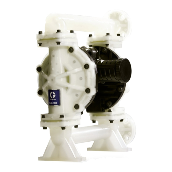
1050P
Polypropylene
1050C
Conductive Polypropylene
with End
Flange
ti13844a
ti13843a
312877A
with Center
Flange
Advertisement
Table of Contents

Related Manuals for Graco Husky 1050 Series


Summary of Contents for Graco Husky 1050 Series
- Page 1 Operation ® Husky 1050 Air-Operated Diaphragm Pump 312877A 1-inch pump with modular air valve for fluid transfer applications 125 psi (0.86 MPa, 8.6 bar) Maximum Fluid Working Pressure 125 psi (0.86 MPa, 8.6 bar) Maximum Air Input Pressure 1050P Polypropylene Important Safety Instructions 1050C Conductive Polypropylene...
-
Page 2: Table Of Contents
Graco Standard Warranty ....24 Graco Information ......24... -
Page 3: Pump Matrix
NOTE: Options for seats, check balls, diaphragms, and seals vary for the 1050A, 1050C, 1050P, and 1050S pump models. To build a pump, use Pump ID the selector tool at www.graco.com or speak with your distributor. ti14103a Pump Center Section and... -
Page 4: Warnings
Warnings Warnings The following warnings are for the setup, use, grounding, maintenance, and repair of this equip- ment. The exclamation point symbol alerts you to a general warning and the hazard symbol refers to procedure-specific risk. Refer back to these warnings. Additional, product-specific warnings may be found throughout the body of this manual where applicable. - Page 5 Warnings WARNING EQUIPMENT MISUSE HAZARD Misuse can cause death or serious injury. Do not operate the unit when fatigued or under the influence of drugs or alcohol. • Do not exceed the maximum working pressure or temperature rating of the lowest •...
-
Page 6: Installation
Before using the pump for the first time, check . 4 are only guides for selecting and install- and retorque all external fasteners. Follow ing system components. Contact your Graco Torque Instructions, page 16. distributor for assistance in planning a system to suit your needs. -
Page 7: Mounting
Installation Mounting wire to a true earth ground. A ground wire and clamp, Part 238909, is available from Graco. The pump exhaust air may contain contam- • Polypropylene: Only conductive polypropyl- inants. Ventilate to a remote area. See Air ene pumps have a ground screw. Standard Exhaust Ventilation on page 8. -
Page 8: Air Line
Installation Check your system electrical continuity after Reed Switch the initial installation, and then set up a regular Pulse Count models are intended for use with schedule for checking continuity to be sure customer-supplied fluid management or inven- proper grounding is maintained. tory tracking systems. -
Page 9: Fluid Supply Line
Installation Key: Air supply line Bleed-type master air valve Air regulator Air inlet Master air valve (for accessories) Air line filter Muffler Grounded air exhaust hose Container for remote air exhaust ti14219a . 2. Vent exhaust air Fluid Supply Line Fluid Outlet Line See F . - Page 10 Installation ti14163a . 3. Typical bung-mount installation (aluminum, 1050A, pump shown) 312877A...
- Page 11 Installation ti14164a . 4. Typical floor-mount installation (polypropylene, 1050P, pump shown) Key for F . 3 and F . 4: N Fluid outlet (Aluminum, F . 3, four ports, one not visible; Plastic, F . 4, center or end flanges available;...
-
Page 12: Fluid Inlet And Outlet Ports
Installation Fluid Inlet and Outlet Ports Graco standard pipe flange kits are available in polypropylene (239005), stainless steel NOTE: Remove and reverse the manifold(s) to (239008), and PVDF (239009). These kits change the orientation of inlet or outlet port(s). include: Follow Torque Instructions on page 16. -
Page 13: Fluid Pressure Relief Valve
Installation Fluid Pressure Relief Valve Some systems may require installation of a Overpressurization also can occur if the pressure relief valve at the pump outlet to pre- Husky pump is used to feed fluid to a piston vent overpressurization and rupture of the pump, and the intake valve of the piston pump pump or hose. -
Page 14: Operation
Operation Operation Pressure Relief Procedure Starting and Adjusting the Pump 1. Be sure the pump is properly grounded. Refer to Grounding on page 7. Trapped air can cause the pump to cycle 2. Check fittings to be sure they are tight. Use unexpectedly, which could result in serious a compatible liquid thread sealant on male injury from splashing. -
Page 15: Datatrak Operation
Maintenance 10. If you are flushing, run the pump long Flushing and Storage enough to thoroughly clean the pump and hoses. 11. Close the dispensing valve, if used. Flush before fluid can dry in the equipment, • 12. Close the bleed-type master air valve. at the end of the day, before storing, and 13. -
Page 16: Torque Instructions
Maintenance Torque Instructions NOTE: Fluid cover and manifold fasteners have a thread-locking adhesive patch applied to the threads. If this patch is excessively worn, the fasteners may loosen during operation. Replace screws with new ones or apply medium-strength (blue) Loctite or equivalent to the threads. - Page 17 Maintenance 312877A...
-
Page 18: Dimensions And Mounting
Dimensions and Mounting Dimensions and Mounting Aluminum (1050A) ti12211a ti12212a 5.0 in. (127 mm) 5.5 in. ti12213a ti14540a (140 mm) J ..3.9 in. (99 mm) A ..12.7 in. (323 mm) K..10.0 in. (254 mm) B ..14.4 in. (366 mm) L .. -
Page 19: Polypropylene (1050P) And Conductive Polypropylene (1050C)
Dimensions and Mounting Polypropylene (1050P) and Conductive Polypropylene (1050C) ti13847a ti13845a 5.0 in. (127 mm) ti13846a ti14541a 10.3 in. (262 mm) J ..3.9 in. (99 mm) A ..13.2 in. (335 mm) K..9.6 in. (244 mm) B ..15.7 in. (399 mm) L .. -
Page 20: Stainless Steel (1050S)
Dimensions and Mounting Stainless Steel (1050S) ti14344a ti14343a 5.0 in. (127 mm) 5.5 in. ti14345a ti14542a (140 mm) L ..1/2 npt(f) air inlet A ..11.8 in. (300 mm) M ..1 in. npt(f) or 1 in. bspt fluid inlet B .. -
Page 21: Performance Charts
Performance Charts Performance Charts Test Conditions: Pump tested in water with inlet submerged. (0.83. 8.3) Fluid Pressure (0.7, 7.0) (0.55, 5.5) Operating Air Pressure (0.41, 4.1) 125 psi (0.83 MPa, 8.3 bar) (0.28, 2.8) 100 psi (0.7 MPa, 7.0 bar) (0.14, 1.4) 70 psi (0.48 MPa, 4.8 bar) (57) -
Page 22: Technical Data
Technical Data Technical Data Maximum fluid working pressure....125 psi (0.86 MPa, 8.6 bar) Air pressure operating range ....20-125 psi (0.14-0.86 MPa, 1.4-8.6 bar) Maximum air consumption . - Page 23 Technical Data Operating Temperature Range NOTICE Temperature limits are based on mechanical stress only. Certain chemi- cals will further limit the maximum operating temperature range. Stay within the temperature range of the most-restricted wetted component. Operating at a temperature that is too high or too low for the components of your pump may cause equipment damage.
-
Page 24: Graco Standard Warranty
With the exception of any special, extended, or limited warranty published by Graco, Graco will, for a period of twelve months from the date of sale, repair or replace any part of the equipment determined by Graco to be defective.
Need help?
Do you have a question about the Husky 1050 Series and is the answer not in the manual?
Questions and answers