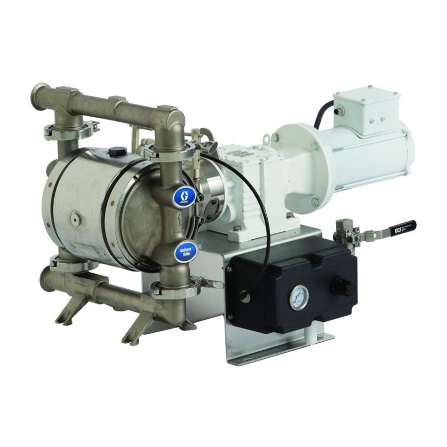
Graco SaniForce 1040e Repair Parts
Electric-operated diaphragm pump
Hide thumbs
Also See for SaniForce 1040e:
- User manual (66 pages) ,
- Operation (64 pages) ,
- Repair parts (40 pages)
Table of Contents
Advertisement
Quick Links
Repair/Parts
SaniForce® 1040e
SaniForce®
SaniForce®
Diaphragm
Diaphragm Pump
Diaphragm
For fluid
fluid transfer
transfer in in in indoor
indoor sanitary
For
For
fluid
transfer
indoor
hazardous
hazardous
hazardous (classified)
(classified) locations
(classified)
professional
professional use
professional
use
use only.
only.
only.
Important Safety
Important
Important
Safety
Safety Instructions
Read all warnings and instructions in this manual and in your
SaniForce 1040e Operation manual before using the equipment.
Save these
these instructions.
instructions.
Save
Save
these
instructions.
For maximum operating pressures,
see the Performance Charts in your
Operation manual.
See pages 6–8 for model information,
including approvals.
1040e Electric
Electric - - - Operated
1040e
Electric
Pump
Pump
sanitary applications.
applications. Not
sanitary
applications.
locations
locations unless
unless otherwise
unless
otherwise stated.
otherwise
Instructions
Instructions
PROVEN QUALITY. LEADING TECHNOLOGY.
Operated
Operated
Not approved
approved for
for use
use in in in explosive
Not
approved
for
use
stated. See
stated.
See Approvals
See
Approvals page
Approvals
3A3168N
explosive atmospheres
atmospheres or or or
explosive
atmospheres
page for
page
for more
for
more information.
more
information. For
information.
EN
For
For
Advertisement
Table of Contents

Related Manuals for Graco SaniForce 1040e


Summary of Contents for Graco SaniForce 1040e
- Page 1 Important Important Safety Important Safety Safety Instructions Instructions Instructions Read all warnings and instructions in this manual and in your SaniForce 1040e Operation manual before using the equipment. Save these these instructions. instructions. Save Save these instructions. For maximum operating pressures, see the Performance Charts in your Operation manual.
-
Page 2: Table Of Contents
Parts..............23 Cart-Mounted Models........29 Approvals............8 Cart............. 31 Overview............9 Kits and Accessories ........35 Troubleshooting..........10 Technical Specifications........36 Repair..............12 Related Manuals Manuals Related Related Manuals Manual Number Title 3A3167 SaniForce 1040e Electric-Operated Diaphragm Pump, Operation 3A3168N... -
Page 3: Warnings
Warnings Warnings Warnings Warnings The following warnings are for the setup, use, grounding, maintenance, and repair of this equipment. The exclamation point symbol alerts you to a general warning and the hazard symbols refer to procedure-specific risks. When these symbols appear in the body of this manual or on warning labels, refer back to these Warnings. - Page 4 Warnings WARNING PRESSURIZED PRESSURIZED PRESSURIZED EQUIPMENT EQUIPMENT EQUIPMENT HAZARD HAZARD HAZARD Fluid from the equipment, leaks, or ruptured components can splash in the eyes or on skin and cause serious injury. • Follow the Pressure Pressure Relief Pressure Relief Procedure Relief Procedure Procedure when you stop spraying/dispensing and before...
- Page 5 Warnings WARNING THERMAL THERMAL THERMAL EXPANSION EXPANSION HAZARD EXPANSION HAZARD HAZARD Fluids subjected to heat in confined spaces, including lines, can create a rapid rise in pressure due to the thermal expansion. Over-pressurization can result in equipment rupture and serious injury.
-
Page 6: Configuration Number Matrix For Fg
Configuration Number Matrix for FG Pumps Configuration Number Number Matrix Matrix for for FG FG Pumps Pumps Configuration Configuration Number Matrix Pumps Check the identification plate (ID) for the Configuration Number of your pump. Use the following matrix to define the components of your pump. -
Page 7: Configuration Number Matrix For Hs And Ph Pumps
Configuration Number Matrix for HS and PH Pumps Configuration Number Number Matrix Matrix for for HS HS and and PH PH Pumps Pumps Configuration Configuration Number Matrix Pumps Check the identification plate (ID) for the Configuration Number of your pump. Use the following matrix to define the components of your pump. -
Page 8: Approvals
Approvals Approvals Approvals Approvals Approvals Approvals Approvals All models are approved to: *Diaphragm materials coded , PT, or combined with ball materials coded EC 1935/2004 comply with: ‡ Pumps with code are approved II 2 G Ex h IIB T3 Gb Diaphragm materials coded combined with ball materials coded Class VI... -
Page 9: Overview
Points: Points: • Pumps are available with an AC or Brushless • BLDC motors are controlled by the Graco Motor DC (BLDC) motor, or with just a gearbox (for Control that is supplied with the pump. applications where a motor is already available). -
Page 10: Troubleshooting
• Follow the Pressure Relief Procedure, page before checking or servicing the equipment. • Check all possible problems and causes before disassembly. See the Operation Manual (3A3167) for troubleshooting or error information on the Graco Motor Control. Problem Cause Solution Problem... - Page 11 Determine and fix the source of the power problem. Operational parameters are See manual 3A3167 for event codes. exceeded. NOTE: NOTE: For problems with a Variable Frequency Device (VFD), see your VFD manual. For problems with the NOTE: Graco Motor Control, see your Operation Manual. 3A3168N...
-
Page 12: Repair
Repair Repair Repair Repair Pressure Relief Relief Procedure Procedure Check Valve Valve Repair Repair Pressure Pressure Relief Procedure Check Check Valve Repair Follow the Pressure Relief Procedure whenever you see this symbol. NOTE: Kits are available for new check valve balls, NOTE: NOTE: diaphragms, and manifold o-rings in a range of... - Page 13 Repair 1040FG 1040HS or or or 1040PH 1040PH 1040FG 1040FG 1040HS 1040HS 1040PH Arrow on both covers must point toward outlet manifold 3A3168N...
-
Page 14: Diaphragm Repair
Repair Diaphragm Repair Repair Diaphragm Diaphragm Repair 4. Loosen the screws and remove the motor fan cover. Turn the motor fan by hand to move the piston fully to one side. NOTE: If the pump is still attached to the motor, NOTE: NOTE: remove the plug (124) and o-ring (134). - Page 15 Repair Reassemble Reassemble Reassemble the the Diaphragms Diaphragms Diaphragms Follow all notes in the illustrations on the following 3. All All Other Other Diaphragms-Metal Other Diaphragms-Metal Pumps Diaphragms-Metal Pumps Pumps important information. page. These notes contain important important a. Thoroughly clean or replace the diaphragm bolt (14).
- Page 16 Repair 2 2 2 - - - Piece Piece Piece ( ( ( PS) ) ) Models Models Models Rounded side faces diaphragm. Apply medium-strength (blue) thread locker to the threads. AIR SIDE markings on diaphragm must face the center housing. If the screw comes loose or is replaced, apply permanent (red) thread locker to diaphragm side threads.
-
Page 17: Center Section Repair
Repair Center Section Section Repair Repair Center Center Section Repair 7. Use a 3/4–16 bolt, screwed into the hole for plug (124), to push out the drive shaft (112). You can also use the bearing bolt (106), but remove the bearing (107) first. - Page 18 Repair Apply medium-strength (blue) thread locker to threads. Torque to 15–25 ft-lb (20–34 N•m). Lips must face IN IN IN toward the center. Apply anti-seize lubricant liberally on the surfaces of the drive shaft assembly. Install the drive shaft assembly with the groove facing up.
- Page 19 Repair Reassemble Reassemble Reassemble the the Center Center Center Section Section Section See the illustrations on the previous page. 5. Install o-ring (109†). 6. Apply anti-seize lubricant on the mating surfaces 1. Clean and dry the center housing (101), the of the drive shaft, as shown in the illustration, center of the piston (102) and the drive shaft page 18.
-
Page 20: Replace Center Bearing
Repair Replace Center Center Bearing Bearing Replace Replace Center Bearing 6. Place the repair tool (A) on the housing with the stepped side down. NOTE: NOTE: NOTE: Follow this procedure only if you suspect that 7. Remove the bearing (D). Use the lower holes on the center bearing is damaged. - Page 21 Repair 9. Use an arbor press and the press-fit tool (E) to install the two bushings (C). Install the bushings flush with the center housing (101). 10. Follow all steps in Reassemble the Center Section, page 3A3168N...
-
Page 22: Replace The Compressor
Repair Replace the the Compressor Compressor Replace Replace Compressor To avoid injury from fire, explosion, or electric shock, all electrical wiring must be done by a qualified electrician and comply with all local codes and regulations. 1. Remove the air line (A1) from the compressor. Disconnect the compressor wires at the terminal block (L1, L2, and ground). -
Page 23: Parts
Parts Parts Parts Parts 1040FG 1040FG 1040FG 3A3168N... - Page 24 Parts 1040FG Parts/Kits Parts/Kits Quick Quick Reference Reference 1040FG 1040FG Parts/Kits Quick Reference Use this table as a quick reference for parts/kits. Go to the pages indicated in the table for a full description of kit contents. Description Qty. Qty. Qty.
- Page 25 Parts 1040HS and and 1040PH 1040PH 1040HS 1040HS 1040PH 3A3168N...
- Page 26 Parts 1040HS and and 1040PH 1040PH Parts/Kits Parts/Kits Quick Quick Reference Reference 1040HS 1040HS 1040PH Parts/Kits Quick Reference Use this table as a quick reference for parts/kits. Go to the pages indicated in the table for a full description of kit contents.
- Page 27 Parts Drive Module Module Drive Drive Module Apply Apply medium Apply medium medium- - - strength strength (blue) strength (blue) thread (blue) thread thread locker locker locker to to to threads. threads. threads. 3A3168N...
- Page 28 Parts Part Part Part Description Description Description Part Part Part Description Description Description — — — WASHER HOUSING, center, assembly; includes items — — — SCREW, cap, hex head, (Ref. 123, 124, 134) M6 x 16 mm (A A A 24Y781 Aluminum —...
-
Page 29: Cart-Mounted Models
Parts Cart - - - Mounted Mounted Models Models Cart Cart Mounted Models 3A3168N... - Page 30 25A882 24Y921 – 120V 17G703 — — — NUT, hex 5/16 25A706 25A879 24Y922 – 240V None 24Y514 CONTROLLER, Graco Motor 25A707 25A880 24Y922 – 240V None — — — SCREW, socket hd cap #10 25A708 25A881 24Y922 – 240V...
-
Page 31: Cart
Parts Cart Cart Cart This parts breakdown reflects item 201. Part Description Part Part Description Description — — — ◊ FRAME, cart — — — †◊ WASHER, flat — — — †◊ WASHER, spring — — — †◊ WHEEL — — — †◊ E-RING 17H262◊... - Page 32 Parts Seats and and Check Check Balls Balls Seats Seats Check Balls Sample Configuration Number Pump Wetted Drive Center Gear Box Fluid Seats Balls Diaphragms Manifold Certifica- Model Section Covers and Section and Motor Gaskets tion Material Material Manifolds 1040 Ball Ball Kits Ball...
- Page 33 Parts Diaphragms Diaphragms Diaphragms Sample Configuration Number Pump Wetted Drive Center Gear Box Fluid Seats Balls Diaphragms Manifold Certifica- Model Section Section and Motor Covers and Gaskets tion Material Material Manifolds 1040 Overmolded Overmolded Overmolded Diaphragm Diaphragm Diaphragm Kits Kits Kits Bolt Bolt- - - Through...
- Page 34 Parts Fluid Repair Repair Kits Kits Fluid Fluid Repair Kits Fluid Section Section Repair Repair Kits, Kits, for for FG FG Pumps Pumps only only Fluid Fluid Section Repair Kits, Pumps only Description Description Description Qty. Qty. Qty. Kit descriptions appear in the following order: Pump model, seat material, ball material, FK1232 1040FG --,CW,SP,EP...
-
Page 35: Kits And Accessories
Includes leak sensor and bushing. NOTE: Also purchase a cable from the following NOTE: NOTE: 17S306 9.8 ft; 3.0 m selections. For systems using a Graco Motor Control, order an extension cable from the first section. For Compressor-to-Controller Compressor-to-Controller Compressor-to-Controller Cables Cables... -
Page 36: Technical Specifications
Technical Specifications Technical Specifications Specifications Technical Technical Specifications SaniForce SaniForce SaniForce 1040e 1040e 1040e Electric Electric Electric- - - Operated Operated Operated Double Double Double Diaphragm Diaphragm Diaphragm Pump Pump Pump Metric Metric Metric Maximum fluid working pressure 70 psi 0.48 MPa, 4.8 bar... - Page 37 Technical Specifications SaniForce SaniForce SaniForce 1040e 1040e 1040e Electric Electric Electric- - - Operated Operated Operated Double Double Double Diaphragm Diaphragm Diaphragm Pump Pump Pump Metric Metric Metric Sound Pressure [tested 3.28 ft (1 m) from equipment] at 70 psi fluid pressure and 50 cpm...
- Page 38 Technical Specifications Fluid Temperature Temperature Range Range Fluid Fluid Temperature Range NOTICE NOTICE NOTICE Temperature limits are based on mechanical stress only. Certain chemicals will further limit the fluid temperature range. Stay within the temperature range of the most-restricted wetted component. Operating at a fluid temperature that is too high or too low for the components of your pump may cause equipment damage.
- Page 39 California Proposition 65 Technical Specifications Specifications for for the the Graco Graco Motor Motor Control Control Technical Technical Specifications Graco Motor Control DC Power Supply Class 2 Power Supply only Approvals UL508C Conformity CE-Low Voltage (2006/95/EC), EMC (2004/108/EC), and RoHS (2011/65/EU) Directives Ambient Temperature -40°F –...
- Page 40 Graco to be defective. This warranty applies only when the equipment is installed, operated and maintained in accordance with Graco’s written recommendations. This warranty does not cover, and Graco shall not be liable for general wear and tear, or any malfunction, damage or wear caused by faulty installation, misapplication, abrasion, corrosion, inadequate or improper maintenance, negligence, accident, tampering, or substitution of non-Graco component parts.
Need help?
Do you have a question about the SaniForce 1040e and is the answer not in the manual?
Questions and answers