Table of Contents
Advertisement
Quick Links
Download this manual
See also:
Quick Manual
FCC NOTICE (Class A)
This device complies with Part 15 of the FCC Rules. Operation is subject to the
following two conditions: (1) this device may not cause harmful interference, and
(2) this device must accept any interference received, including interference that
may cause undesired operation.
Federal Communications Commission Statement
NOTE- This equipment has been tested and found to comply with the limits for a Class A
digital device, pursuant to Part 15 of the FCC Rules. These limits are designed to provide
reasonable protection against harmful interference in a residential installation. This
equipment generates uses and can radiate radio frequency energy and, if not installed
and used in accordance with the instructions, may cause harmful interference to radio
communications. However, there is no guarantee that interference will not occur in a
particular installation. If this equipment does cause harmful interference to radio or
television reception, which can be determined by tuning the equipment off and on, the
user is encouraged to try to correct the interference by one or more of the following
measures:
Reorient or relocate the receiving antenna.
Increase the separation between the equipment and receiver.
Connect the equipment into an outlet on a circuit different from that to which the
receiver is connected.
Consult the dealer or an experienced radio/television technician for help.
Class A ITE:
Class A ITE is a category of all other ITE which satisfies the class A ITE limits but not the
class B ITE limits. Such equipment should not be restricted in its sale but the following
warning shall be included in the instructions for use:
Warning - This is a class A product. In a domestic environment this product may cause
radio interference in which case the user may be required to take adequate measures.
CE Class A (EMC)
This product is herewith confirmed to comply with the requirements set out in
the Council Directives on the Approximation of the laws of the Member States
relating to Electromagnetic Compatibility Directive 2004/108/EEC.
Warning - This is a Class A product. In a domestic environment this product may cause
radio interference in which case the user may be required to take adequate measures to
correct this interference.
DISCLAIMER
No warranty or representation, either expressed or implied, is made with respect to the
contents of this documentation, its quality, performance, merchantability, or fitness for a
particular purpose. Information presented in this documentation has been carefully
checked for reliability; however, no responsibility is assumed for inaccuracies. The
information contained in this documentation is subject to change without notice.
In no event will AVerMedia be liable for direct, indirect, special, incidental, or
consequential damages arising out of the use or inability to use this product or
documentation, even if advised of the possibility of such damages.
TRADEMARKS
AVerVision is registered trademarks of AVerMedia INFORMATION, Inc. IBM PC is a
registered trademark of International Business Machines Corporation. Macintosh is a
registered trademark of Apple Computer, Inc. Microsoft is a registered trademark and
Windows is a trademark of Microsoft Corporation. All other products or corporate names
mentioned in this documentation are for identification and explanation purposes only, and
may be trademarks or registered trademarks of their respective owners.
COPYRIGHT
© 2008 by AVerMedia INFORMATION, Inc. All rights reserved. No part of this publication
may be reproduced, transmitted, transcribed, stored in a retrieval system, or translated
into any language in any form by any means without the written permission of AVerMedia
INFORMATION, Inc.
THE MARK OF CROSSED-OUT WHEELED BIN INDICATES THAT THIS
PRODUCT
MUST
HOUSEHOLD WASTE. INSTEAD, YOU NEED TO DISPOSE OF THE
WASTE EQUIPMENT BY HANDING IT OVER TO A DESIGNATED
COLLECTION POINT FOR THE RECYCLING OF WASTE ELECTRICAL
AND ELECTRONIC EQUIPMENT. FOR MORE INFORMATION ABOUT
WHERE TO DROP OFF YOUR WASTE EQUIPMENT FOR RECYCLING,
PLEASE CONTACT YOUR HOUSEHOLD WASTE DISPOSAL SERVICE OR
THE SHOP WHERE YOU PURCHASED THE PRODUCT.
NOT
BE DISPOSED OF WITH YOUR OTHER
Advertisement
Table of Contents

Related Manuals for Avermedia AVerVision SPB350


Summary of Contents for Avermedia AVerVision SPB350
- Page 1 © 2008 by AVerMedia INFORMATION, Inc. All rights reserved. No part of this publication may be reproduced, transmitted, transcribed, stored in a retrieval system, or translated into any language in any form by any means without the written permission of AVerMedia INFORMATION, Inc.
- Page 2 Ba tte r y S a f et y I n f o rmat i on Store the batteries in a cool dry place. Do not dispose of used batteries in domestic waste. Dispose of batteries at special collection points or return to point of sale if applies. Remove the batteries during long periods of non-use.
-
Page 3: Table Of Contents
Anti-glare ...E-9 Control Panel Light Color ...E-9 Using the Infrared Remote Control ... E-9 Touch Button Control Panel... E-11 Using AVerVision SPB350 as a Mass Storage... E-12 OSD Navigation Tree... E-13 Menu Functions... E-14 Technical Specifications ... E-17 Image ...E-17 Optics ...E-17... -
Page 5: Introduction
The power cord varies depending on the standard power outlet of the country where it is sold. 34mm Microscope Adapter ® AVerVision SPB350 package contains the following: ® AVerMedia AVerVision SPB350 Anti-glare Sheet Power Adapter Power Cord... -
Page 6: Rgb In Port
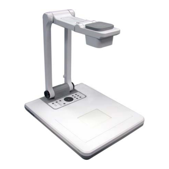
The illustrations below identify the parts of SPB350. Overhead light Camera head Camera lens Left panel Control panel Light box Label slot IR sensors 10. Rear panel 11. Right panel 12. Video output switch 13. Light box power button 14. DC 12V port 15. -
Page 7: Making The Connections
The ports on the rear and right panel of SPB350 enable you to connect the unit to a computer, graphics display monitor or LCD/DLP projector, TV or other device. Illustrated below are the ports that are located at the rear and right panel of SPB350 with their corresponding labels. -
Page 8: Connecting The Power Adapter
Locate the RGB (VGA) or DVI-I input port of the display device and connect it to RGB/DVI-I OUTPUT port of SPB350. If you are not sure, please refer to the user manual of the device. Make sure the Video Output switch is set to RGB. -
Page 9: Connecting A Tv
Locate the VIDEO (yellow), S-VIDEO or SCART RGB input port of the TV or Video equipment (i.e., VCR) to record your presentation on a videotape and connect it to S-VIDEO or VIDEO OUTPUT port of SPB350. If you are not sure, please refer to the user manual of the TV or Video equipment. -
Page 10: Connecting To A Computer Via Usb Connection
Connecting to a Computer via USB Connection Locate the USB port of the computer or laptop and connect it to USB port of SPB350. This enables you to use SPB350 as a USB Camera and to transfer the captured images from the memory source and to computer. -
Page 11: Arm
This section provides useful tips on how to adjust the SPB350 to meet your needs. The arm must be unfolded fully in upright position. 90° Correct Operating Position 90° VIDEO OUTPUT LIGHT BOX Camera Head The camera head can be folded up 90° and turned 90° to the left and right. To display an object more than 50cm away from the camera, unscrew the close-up lens. -
Page 12: Infrared Sensor
Aim the remote control at the infrared sensors to operate the unit. Light box Press LIGHT BOX button on the left panel of SPB350 to turn on and off light. Use this to view negative film, x-ray and 35mm slides. -
Page 13: Anti-Glare
Orange : The unit is in standby mode. Use the SPB350 Remote Control to enhance your presentation by having the ability to switch between three (3) presentation modes and access various features. To use the remote control, first insert the batteries (2 “AAA” size batteries are provided) into the battery compartment at the back of the remote. - Page 14 DELETE to permanently remove the selected image from the selected memory source. - PC mode displays the video signal from the RGB IN port of SPB350. (7) CAP/DEL - Capture a still image in Camera mode. The captured image is saved in the selected memory source at 1600 x 1200 resolution and the built-in memory can store up to 80 images.
-
Page 15: Touch Button Control Panel
◄ & ► or ▲&▼ buttons. To switch to different split screen type, press MENU, go to SPLIT SCREEN and select between vertical or horizontal splitting type. The touch button control panel located on the top side of AVerVision SPB350 provides quick access to commonly used functions. POWER... -
Page 16: Shuttle Wheel
You MUST read and follow the instructions below BEFORE connecting the USB cable. Every time when using the SPB350 as Mass Storage, the following MUST be done: 1. Select the memory source. To select the memory source, press MENU >... -
Page 17: Osd Navigation Tree
VIDEO OUTPUT OSD For TV output, RESOLUTION is not included in the menu list. PLAYBACK OSD E-13... -
Page 18: Menu Functions
The MENU functions of SPB350 enhance fine-tuning your screen display, set the timer, select OSD language and more. Press the MENU button to call up and exit from the main menu or sub-menu display. Then use ▲or▼ buttons to select the items in the menu list. - Page 19 If you are presenting in a low-light condition, Night View enables the image of the object to appear as though under normal lighting conditions. SPB350 can automatically adjust the exposure to compensate for the adverse condition, but the captured image will appear to be in slow motion.
- Page 20 OSD Menu Description IMAGE SETTING > IMAGE > BRIGHTNESS EXPOSURE WHITE BALANCE Use ►or◄ buttons to increase or decrease the brightness level and BRIGHTNESS improve the visibility of the image. The brightness level can be set up to CONTRAST RESOLUTION IMAGE SETTING >...
-
Page 21: Technical Specifications
OSD Menu Description MENU DEFAULT EFFECT Press ► and use ▲or▼ buttons to select YES to restore to original MIRROR PRESENTER factory default setting or NO to exit then press ►/ENTER to make the SPLIT SCREEN selection. SETTING TIMER CAPTURE RECALL DEFAULT Image... -
Page 22: Send Command Format
SPB350 can be controlled using a PC through RS-232 connection. Computer Laptop Make sure the RS-232 cable matches the cable spec design. PC COM Port DSUB-9P (Female) RI (CI) Star bit Data bit Stop bit Parity bit X parameter Baud rate(Communication speed) Send Command Format: Send Format︰0x52 + 0x05 + 0x01 + Command + 0x53 + CheckSum... -
Page 23: Set Value Format
FUNCTION PC PASS THROUGH LAMP ON/OFF LIGHT BOX ON/OFF NEAR ZOOM IN ZOOM OUT ZOOM RESET FREEZE ROTATE MIRROR EFFECT BRT UP BRT DOWN AUTO IMAGE TIMER PROFILE CAPTURE / DELETE SPLIT SCRN AVERBOX ON / OFF AVERVISOR ON / OFF AVERBOX COLOR Set Value Format: Send Format︰0x52 + 0x0B + 0x03 + Data[0] + Data[1] + Data[2] + 0x53 + CheckSum... -
Page 24: Get Value Format
When you turn on the computer, it will auto-detect the type of monitor you have. During auto-detection, there won’t be any display on your presentation screen. To avoid this problem, connect your computer and all the necessary cables to the AVerVision SPB350 first before you power on your computer. -
Page 25: Limited Warranty
This limited warranty extends only to You as the original purchaser. Except for the foregoing, the Product is provided “AS IS.” In no event does AVerMedia warrant that You will be able to operate the Product without problems or interruptions, or that the Product is suitable for your purposes.
Need help?
Do you have a question about the AVerVision SPB350 and is the answer not in the manual?
Questions and answers