Advertisement
Quick Links
Advertisement

Related Manuals for SystemAir PK-I-R-EI60S


Summary of Contents for SystemAir PK-I-R-EI60S
- Page 1 www.systemair.com...
- Page 2 Fire Dampers Circular Fire Dampers PK-I-R-EI60S, -EI90S and -EI120S Systemair Fire dampers are manufactured to comply with latest European Standards. With wide product range and sizes for 60, 90 and 120 minute resistance for round and rectangular ducting. All dampers as standard are designed and certified for EI-S performance conformity.
- Page 3 Fire Dampers Circular Fire Dampers Damper Codes and Types DAMPER DAMPER CLOSED OPENED ZV; Basic model with manual operating lever with spring return release driven by a fusible thermal link set at 72C. Optional extras: DV1; Closed position indication with 24V contact switch DV1-2;...
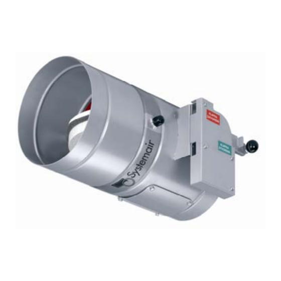
- Page 4 Fire Dampers Circular Fire Dampers Actuator driven Fire Dampers: Circular fire damper with actuator DV7; Spring return actuator driven fire damper (230V) complete with Thermal release mechanism and Auxiliary Switches DV9-T; Spring return actuator driven fire damper (24V) complete with Thermal release mechanism and Auxiliary Switches DV9-T-ST;...
- Page 5 Fire Dampers Square Fire Dampers PK-I-S-EI90S and -EI120S Systemair Fire dampers are manufactured to comply with latest European Standards. With wide product range and sizes for 90 and 120 minute resistance for square or rectangular ducting. All dampers as standard are designed and certified for EI-S performance conformity.
- Page 6 Fire Dampers Square Fire Dampers Damper Codes and Types ZV; Basic model with manual operating lever with spring return release driven by a fusible thermal link set at 72C. Optional extras: DV1; Closed position indication with 24V contact switch DV1-2; Open and Closed position indication with 24V contact switches DV2;...
- Page 7 Fire Dampers Square Fire Dampers Unit weight (Kg) H/ L 1000 1100 1200 1400 1500 1600 11.3 12.1 12.9 13.7 14.7 15.9 17,2 18,7 20,4 22,1 24,1 26,2 28,7 30,4 32,0 10.4 12.4 13.2 14.2 15.1 16.2 17.5 19,0 20,6 22,5 24,3 26,5...
- Page 8 Fire Dampers Installation of Round Fire Dampers Fire damper placement and clearances Damper release mechanism or actuator can be located on any side of the wall or ceiling. However it must be positioned in such way that there is easy access provided for inspection or service. Examples of damper locating can be seen in fig.
- Page 9 Installation of Round fire dampers Building in the PK-I-R in the wall, with gypsum mixture An intumescent gypsum mixture can be used to seal the opening section between the wall and the fire damper. The entire wall cross-section must be perfectly filled with gypsum mixture The opening provided for this installation should be no less than Ød + 160 mm.
- Page 10 Fire Dampers Installation of Round fire dampers Installation of PK-I-R into the wall using Rockwool To seal between the wall and the fire damper Rockwool with a min. density of 80-100 kg/m can be used. Once the fire damper is properly secured into the wall, cover plates made of calcium-silicate can be used to close or finish the wall openings (fig.
- Page 11 Operations and commissioning of Round Fire dampers Pressure loss calculation for square dampers types: - PK-I-R-EI60S - PK-I-R-EI90S - PK-I-R-EI120S Damper pressure losses are stated by the calculation. Coefficients of local pressure losses, which refer to nominal cross - section refered to ød are stated in the tables. Pressure loss for exact damper is stated by calculation according to the scheme: ρ...
- Page 12 Fire Dampers Installation of Square Fire Dampers min.100 Installation of Square fire dampers PK-I-S-EI90S and 120S into the wall To seal between the wall and the fire damper Rockwool with a min. density of 80-100 kg/m can be used. Once the fire damper is properly secured into the wall, cover plates made of calcium-silicate can be used to close or finish the wall openings (fig.
- Page 13 Fire Dampers Installation of Square Fire Dampers Installation Opening and Covers: Opening dimension and clearance required for Square dampers to be imbedded into the wall is noted her on Figures 13 a & 13b Covers are available if needed on site as optional extra to secure and close the opening insulation between the wall and the fire dampers.
- Page 14 Fire Dampers Operations & Maintenance of fire dampers Putting the damper into operation Dampers in standard manufacture- ZV and with additional equipment- DV1÷DV6 Mechanical triggering By pulling the securing pivot (2) we lock-off the adjusting lever of the mechanism (1) and we move it from the CLOSED position to OPEN position.
- Page 15 Operations & Maintenance of fire dampers Damper electrical function check If the damper is in manufacture DV1÷DV6 with electromagnet it is necessary to test the mechanism function also with electromagnet. Electromagnet receives the signal for actuating (for example from the central building system) releases the actuating lever (4) and mechanism closes.
- Page 16 Operations & Maintenance of fire dampers Damper el. function check If the damper is in manufacture DV3÷DV6 with electromagnet it is necessary to test the mechanism function also with electromagnet. Electromagnet receives the signal for actuating (for example from the central building system) releases the actuating lever (4) and mechanism closes.
- Page 17 Operations & Maintenance of fire dampers Visual check During visual check are possible visible damages on the damper parts checked. From outer side of the damper is damper surface, panel with release mechanism (for manufactures ZV and DV1-DV6) or actuator (for manufactures DV7, DV9-T and DV9-T-ST) checked.
- Page 18 Operations & Maintenance of fire dampers Replacement of Fusible Link: Heat fuse is located inside the damper casing. From the design point of view it is a part of the panel with release device. Heat fuse consists of two parts connected with solder made of low- fusible alloy of non-steel metals.
- Page 19 Operations & Maintenance of fire dampers Electrical function check Accessory types: DV3 – DV6 Electromagnet receives a signal to trigger (for example, from the central system of the building), releases the release lever (4) and the mechanism closes. Adjusting lever (1) immediately moves from position OPEN to position CLOSED.
- Page 20 Operations & Maintenance of fire dampers Operating diary: Putting the Fire damper into operation Signature and date of Date of putting into operation Text- found faults and defects control ling technician Special controls Signature and date of Date of control Text- found faults and defects control ling technician...
- Page 21 Declaration of conformity...
- Page 22 (stamp and signature) Warranty conditions: 1. IMOS-Systemair s.r.o. provides warranty for all produced Fire dampers PKI, the warranty is 24 months from mounting the product and putting it into operation, max. 30 months from the shipment date. 2. The product is tested in the production factory before the shipment. The producer guarantees, that the features of the product shall be according to the related technical standards during the whole warranty period, assuming that the customer uses it in a way stated in operating instructions.
- Page 23 Fire damper accessories End Switches & Electromagnet release Electrical connection Terminal switch is used for signaling damper leaf position. As standard it is connected for signalization of damper leaf closing. As standard is delivered type – Schneider Electric: XCKN2118G11. Technical data XCKN2118G11 Feeding voltage AC 240 V, 50/60Hz, 3 A...
- Page 24 Fire dampers Fire Damper Valves PV-I-R-EI60S, -EI90S and -EI120S Fire damper air valves are manufactured and tested to latest European standards. Tested and certified for resistance classes 60, 90 and 120 minutes. Fire damper valves are available in 3 sizes: 100, 125, 160 and 200mm and are all equipped as standard with thermal fusible link set at 72C.
- Page 25 Shut-Off fire dampers and Intumescent Grills BFD: BFD fire damper shutter valves are designed to be used for small ventilation applications. Ideal for small to multi residential buildings to protect the habitants of fire and Smoke risks. BFD fire dampers are tested and are conform to EN 1366-2 to suit installations of 60, 90 and 120minuts.
- Page 26 Intumescent Grills IFG-S-60 and -120 Intumescent fire grills types IFG-S-60 or -120 are designed to be used as transfer grills with fire resistance barrier for 60 and 120minutes. Constructed with intumescent strips housed in plastic, all blades are set horizontal and vertically to assure lowest pressure loss for air transfer.
- Page 27 Fire dampers controls Actuators & Control accessories Actuator operation Types: DV7 / DV8 / DV9-T / DV9-T-ST For operation of damper blade are used actuator BELIMO type BLF24-T / ST, BLF230-T, BF24-T / ST, BF230-T with return spring. Type BLF is used for round dampers to ø500 mm included. Type BF is used for round dampers above ø500 mm.
- Page 28 Fire dampers controls Actuators & Control accessories Actuator operation Types: DV7 / DV8 / DV9-T / DV9-T-ST For operation of damper blade are used actuator BELIMO type BLF24-T / ST, BLF230-T, BF24-T / ST, BF230-T with return spring. Type BLF is used for round dampers to ø500 mm included. Type BF is used for round dampers above ø500 mm.
- Page 29 Fire dampers controls Actuators & Control accessories BLF24-T, BLF24-T-ST Nominal voltage AC 24 V, 50/60 Hz / DC 24 V Nominal voltage range AC 19,2 ... 28,8 V / DC 21,6 ... 28,8 V Tf1: duct outside temperature 72 ºC Activation temperature of thermal fuses Tf2 + Tf3: duct inside temperature 72 ºC Power consumption...
- Page 30 Fire dampers controls Actuators & Control accessories BLF230-T Nominal voltage AC 230 V, 50/60 Hz Nominal voltage range AC 198 ... 264 V Tf1: duct outside temperature 72 ºC Activation temperature of thermal fuses Tf2 + Tf3: duct inside temperature 72 ºC Power consumption - motoring 6 W @ nominal torque...
- Page 31 Fire dampers controls Actuators & Control accessories BF24-T, BF24-T-ST Nominal voltage AC 24 V, 50/60 Hz / DC 24 V Nominal voltage range AC 19,2...28,8V / DC 21,6...28,8 V Tf1: duct outside temperature 72 ºC Activation temperature of thermal fuses Tf2 + Tf3: duct inside temperature 72 ºC Power consumption - motoring...
- Page 32 Fire dampers controls Actuators & Control accessories BF230-T Nominal voltage AC 230V, 50/60 Hz Nominal voltage range AC 198...264 V Tf1: duct outside temperature 72 ºC Activation temperature of thermal fuses Tf2 + Tf3: duct inside temperature 72 ºC Power consumption - motoring 8 W @ nominal torque - holding...
- Page 33 Fire dampers controls Belimo Controls & Accessories Thermoelectrical release device with control button Thermoelectrical release device controls closing of the leaf in case of exceeding marginal temperature- accident position. Device contains three thermal fuses Tf1 , Tf2 and Tf3. If the ambient temperature exceeds 72°C thermal fuse Tf1 will break or if the temperature inside the damper exceeds 72°C thermal fuses Tf2 and Tf3 will break.
- Page 34 Fire dampers controls Belimo Controls & Accessories Communication and control unit BKS24-1B + ZSO-11 BKS24-1B + ZSO-11is used for control and monitoring of fire damper position of damper leaf - open / close. For connection of damper actuator to this system it is necessary to use communication and supply unit BKN230-24.
- Page 35 Fire dampers controls Belimo Controls & Accessories Communication and control unit BKS24-9A BKS24-9A is used for control and monitoring of fire damper position – open / close of damper leaf. For connection of damper actuator to this system it is necessary to use communication and supply unit BKN230-24.
- Page 36 Systemair AB SE-739 30 Skinnskatteberg, Sweden Tel +46 222 440 00 Fax +46 222 440 99 mailbox@systemair.se www.systemair.com...
- Page 37 Fire air grilles www.systemair.com...
- Page 38 The present technical specifications define sizes, properties, scope of utility and manufacture of fire partition dampers.The specifications apply to the design, ordering, production, acceptance and use of these products from June 1st, 2006. General PVM Partition Fire Dampers are used as a fire shut- off Grilles IMOS- PVM Partition Fire Dampers are manu- element, which connects two two adjacent fire areas factured from fire resistant material (D1) based on STN...
- Page 39 Manufacturing the grille – Basic set consists of grille with fusible link - ZV+ terminal switch indicating “CLOSED”- voltage 24V AC/DC - ZV+ terminal switch indicating “CLOSED”- voltage 230V AC - ZV+ grille with servo motor and thermoelectric switch BELIMO BLF 230-T, working voltage 230V AC, indicating “...
- Page 40 Product ordering The following information and data must be included in the order: Designation XXX - XxX - XXX / RAL..Fire Air Grille width (nominal dimension in mm) height (nominal dimension in mm) Manufacture RAL of protecting outer grille RALxxxx standard RAL 9007 Ordering example: PVM 200x520 DV1...
- Page 41 Figure 4. Installation of PVM in fire-rated partition construction with variable thickness Figure 5 Dismounting of the terminal block from IMOS-PVM with actuator. Scheme 1. Limit switch XCKN2118G11 (manufacture DV1 and DV2) Technical parameters XCKN2118G11 pover voltage AC 240V, 50/60 Hz, 3A DC 250V, 0.1A protection system IP 65...
- Page 42 Scheme 2. Servodrive Belimo BLF 24-T Technical parameters BFL24-T Feeding voltages AC 24V 50/60 Hz, DC 24V Function range AC 19.2 – 28.8V DC 21.6 – 26.4V Activation temperature of thermal fuses Tf1: duct inner temperature 72 TF2: duct inner temperature 72 C * (order No.
- Page 43 Technical parameters BFL230-T Feeding voltages AC 24V 50/60 Hz Function range AC 198 – 264V Activation temperature of thermal fuses Tf1: duct inner temperature 72 TF2: duct inner temperature 72 C * (order No. ZBAE72) Power input - during spring fensing - in idle position - dimensioning 7 VA (1 max.
- Page 44 Systemair AB SE-739 30 Skinnskatteberg, Sweden Tel +46 222 440 00 Fax +46 222 440 99 mailbox@systemair.se www.systemair.com...
- Page 45 Smoke dampers www.systemair.com...
- Page 46 These specifications define the size, properties, and application range and construction features of DKI smoke dampers.The specifications apply to designing, ordering, manufacturing, acceptance, delivery and use of these prod- ucts as of 1st May 2007. General Smoke damper (hereinafter as damper) is a component upon electrical impulse to enable exhaust of heat and of systems used for outlet of smoke and heat.
- Page 47 At the temperature up to 600 C is the integrity and Damper description tightness of closed damper 120 minutes according to DKI-1 damper casing consists of two parts made of the classification standard EN 13 501- 4 E 600 S 120 zinc-plated sheet.These two parts are connected to- gether with flange connection, which is secured with SINGLE ve(d), ho(d) 500AA i<->o c 10 000 (SINGLE-...
- Page 48 Technical Conditions Main dimensions and weights Upon an agreement with the purchaser the producer can deliver dampers in dimensional range from Main dimensions and weights of dampers are stated in 200x200 to 1500x 800, in this case classification enclosed tables.Weights refer to basic damper versions E 600 S 120 is valid.With dampers from the dimension with servo drive.
- Page 49 Damper design and manufacture Stating the damper pressure losses Damper pressure losses are stated by calculation. Coefficients of local pressure loss that refer to nominal damper cross- section axb or cross-section corresponding ød are stated in the table no.2 Pressure loss for particular damper is stated by calculation with the formula: P z = ζ...
- Page 50 Damper embeddings Fig.3 Horizontal damper fitting on the duct- EN 1366-9 Fig.4 Horizontal damper fitting in the duct- EN 1366-9 Fig.5 Vertical damper fitting on the duct-EN 1366-9 Fig.6 Vertical damper fitting in the duct- EN 1366-9...
- Page 51 Electrical elements, schemes of connecting Scheme of connecting the smoke damper Scheme of connecting smoke damper (with (with servo drive for 24V and control unit servo drive for 230V) to electro- installation BKNE 230-24) to electro-installation. - for power supply 230V- use anti- fire cable J 3x1 with fire resistance min.
- Page 52 Scheme of connecting the central unit BKSE 24-6 to control unit BKNE 230-24 1- upholding clasp 2- description (zone) 3- description (damper) 4- LED diode red (failure) 5- Button PRG 6- LED diode yellow(damper position: OPENED) 7- LED diode yellow (damper position: CLOSED) 8- Button SET/ INIT 9- Screwing terminals Technical data...
- Page 53 Scheme of principle of BKSE 24-6 (example)
- Page 54 Scheme of connecting BKNE 230-24 1- connecting the net AC 230V 2- connecting the plug for drive Belimo 24V 3- terminal 7-pole 4- cable lead through for drive Belimo 5- cable lead through for conductor 2 6- LED cursor green ( damper position: closed) 7- LED cursor yellow ( damper position: opened)
- Page 55 Scheme of connecting servo drive Belimo BE 230-12 Technical data BE 230, BE 230-12 Nominal voltage AC230V 50/60 Hz Nominal voltage range AC198 – 264 V For wire sizing 15 VA (lmax. 7.9A @ 5 ms) Power consumption - motoring - holding 0,5W Connection cable...
- Page 56 Scheme of connecting servo drive Belimo BE 24-12ST Technical data BE 24-ST, BE24-12-ST Nominal voltage AC24V 50/60 Hz DC 24V Nominal voltage range AC19.2 ... 28.8 V For wire sizing 18 VA (l max. 8.2A @ 5 ms) Power consumption - motoring - holding 0,5W...
- Page 57 Scheme of connecting servo drive Belimo BLE-230 Technical data BE 230 Nominal voltage AC230V 50/60 Hz Nominal voltage range AC198V ... 264 V Switching thresholds min. ON voltage AC198V Switching thresholds max. OFF voltage AC100V Power consumption - motoring 4W @ menovity moment - holding 0,5W - For wire sizing...
- Page 58 Safety notes: Signaling Servo drive is assigned for use only based on above Two micro switches with fixed settings are installed in specified parameters. Be careful with power supply! the actuator for indicating the damper end positions. Adjusting, mounting, and getting the drive to operation The position of the damper blade can be read off on a are allowed only for damper producer.
- Page 59 Servo drive for actuation of smoke dampers with rotation angle 90- 24V. Belimo BLE-24 Technical data BLE24 Electrical data Nominal voltage AC24V 50/60 Hz /DC 24V Nominal voltage range AC19.2V ... 28.8 V /DC 21.6V ... 28.8V Switching thresholds min. ON voltage AC19.2V /DC 21.6V Switching thresholds max.
- Page 60 Systemair, s.r.o. Damper is delivered as assembled. Producer provides 24 months Storage warranty from the dispatch date for the dampers DKI-1.
- Page 61 Appendix Any deviations from the present technical specifications are subject to agreement with the manufacturer.The man- ufacturer hereby reserves the right to technical innovations without prior notice to customers and holders of this TPI( technical conditions). Related standards STN 73 0802 Fire safety of buildings.
- Page 63 Systemair AB • SE-739 30 Skinnskatteberg, Sweden Tel +46 222 440 00 • Fax +46 222 440 99 mailbox@systemair.se • www.systemair.com...
Need help?
Do you have a question about the PK-I-R-EI60S and is the answer not in the manual?
Questions and answers