Elesa MPI-R10 Operating Instruction
Electronic magnetic meter
Hide thumbs
Also See for MPI-R10:
- Operating instructions manual (12 pages) ,
- Operating instruction (43 pages)
Table of Contents
Advertisement
Quick Links
Advertisement
Table of Contents

Related Manuals for Elesa MPI-R10


Summary of Contents for Elesa MPI-R10
- Page 1 MPI-R10 Electronic Magnetic Meter OPERATING INSTRUCTION...
-
Page 2: Table Of Contents
MPI-R10 Magnetic measuring system Contents 1. Safety Instructions 2. System description 3. Installation Display installation Sensor installation Magnetic band installation 4. Switching on the system Switching off the system (only for storage) 5. Display 6. Key function 7. Operating mode... -
Page 3: Safety Instructions
MPI-R10 Magnetic measuring system 1. Safety Instructions General remarks The equipment is designed and assembled according to the latest existing regulations. The equipment is delivered to the customer in perfect working order and in line with all safety-relevant conditions. To maintain this status of the... -
Page 4: System Description
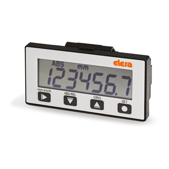
2. System description The MPI-R10, made of a LCD multifunction display that connected with a dedicated sensor FC-MPI, combined with the Elesa magnetic band M-BAND-10, is a complete system for the measurement of linear and angular displacement. - Page 5 MPI-R10 Magnetic measuring system Mechanical and electrical characteristics Power supply Lithium battery 1/2 AA 3.6 V Battery life 4 years 7-digit LCD of 12 mm height and special Display characters Reading scale -199999; 999999 Number of decimal digits programmable Programmable measuring unit...
- Page 6 MPI-R10 Magnetic measuring system The magnetic band M-BAND-10 is made of two separate parts: the magnetic band and the cover strip. The magnetic band is made of a magnetic tape, a carrier strip and an adhesive tape (Fig.2). The cover strip is made of a protection strip and an adhesive tape (Fig.1).
-
Page 7: Installation
3.1 Display installation 1. Drill the panel according to the template dimensions reported. 2. Remove all drilling burrs before fitting the MPI-R10. 3. Fit the lower part of the case into the housing. 4. Press onto the upper part until the case is completely snapped in. -
Page 8: Switching On The System
MPI-R10 Magnetic measuring system 4. Switching on the system After you have read and understood the section “Safety Instructions”, proceed by switching on the indicator. To switch the indicator on: mm-inch - hold the key - press the key The display will light up and the indicator is ready to be used. -
Page 9: Key Function
MPI-R10 Magnetic measuring system 6. Key function Operating Programming mode mode Parameter selection / Keep pressed for 3 sec to enter the programming Confirm of parameter mode change Programmable with one of the following options (see voice of the menu cap. 8.3):... - Page 10 MPI-R10 Magnetic measuring system Key’s Operating combination mode Programmable with one of the following options (see the 0 _ _ _ _ _ 0 voice of the menu – cap. 8.3): [DEFAULT]: show and set the parameter. mm-inch PrOGOrG OriGin : show and set the parameters.
-
Page 11: Operating Mode
MPI-R10 Magnetic measuring system 7. Operating mode 7.1 Absolute / incremental measuring mode selection ABS-REL Press the key to select the absolute or incremental measuring mode. The measuring mode selected is shown on the display by the symbols: - ABS : absolute measuring mode. - Page 12 MPI-R10 Magnetic measuring system 7.3 Setting the absolute reference The system allows you to store up to 10 values of compensation offsets (see OFFSEt in cap. 8.2). This allows you to adjust the value shown on the display in such a way that takes into account, for example, wear or tool change.
-
Page 13: Target Positions
MPI-R10 Magnetic measuring system 7.5 Target positions MPI-R10 allow to set up to 32 target positions to store relevant machine configuration setting. To program the targets: - selet tArGEtS in the main menu (see cap 8.3) - select PrOG_TG (see cap. 8.4) -
Page 14: Angular Measurement
7.6 Angular measurement MPI-R10 allow to measure angular displacements. To obtain the correct measurement, is needed to set the parameter Radius with the measure of the radius of the arc where the magnetic band is placed. -
Page 15: Programming Mode
MPI-R10 Magnetic measuring system 8. Programming mode Press the key for 3 seconds to enter the programming mode. Depending on the setting of PASS parameter (see cap. 8.2), the system may require you to enter a password. ABS-REL Press the key... - Page 16 MPI-R10 Magnetic measuring system 8.2 Device parameters (in alphabetic order) Parameter Description Available options Default Programmable value: 0.000001 +/- 9.999999. Angular scale 0.00000 cannot be accepted Deg corr 1.000000 correction (the coefficient is automatically set to 1.00000). The parameter allows to define...
- Page 17 MPI-R10 Magnetic measuring system Parameter Description Available options Default Programmable value : Res = 1: -999999 ÷ 999999 Res = 0.1: Reference value Origin 0000.00 -99999.9 ÷ 99999.9 Res = 0.01: -9999.99 ÷ 9999.99 Res =0.001: -999.999 ÷ 999.999 ON: the system requires the password 22011 to enter the programming mode.
- Page 18 MPI-R10 Magnetic measuring system Parameter Description Available options Default Programmable value: 1; 2; 3; 4; 5 Reading max speed Speed The parameter set the maximum speed of the movement in m/s that can be correctly read. Programmable value: Res = 1: -999999 ÷...
-
Page 19: Main Menu Tree
MPI-R10 Magnetic measuring system 8.3 Main menu tree dir-- --dir OriGin -999999 ÷ 999999 OFS 0 OFFSET -999999 ÷ 999999 OFS 9 If mm: 1, 0.1,0.01 If inch 1, 0.1, 0.01, 0.001 LinCorr 0.000001÷9.999999 dEGCorr 0.000001÷9.999999 Radius 0.01÷9999.99 AnGuLAr dEG_rES 1, 0.1, 0.01... -
Page 20: Target Menù Tree
MPI-R10 Magnetic measuring system 8.4 Target menù tree ABS-REL PtrG 01 If mm -9999.99÷9999.99 P r O G _ t G … If inch -9999.99÷9999.99 PtrG 32 If Deg -99999÷99999 LtrG 01 L o a d _ t G …... -
Page 21: Revision
MPI-R10 Magnetic measuring system 8.5.4 Correction coefficients To improve the corerectness of the measurement, MPI-R10 allow to set two correction factors that take into account about differencies between ideal and actual installation of the magnetic band: - LinCorr : is the ratio between the actual mesurement and the value measured by the device in linear measurements. -
Page 22: Display Messages And Troubleshoting
MPI-R10 Magnetic measuring system 10. Display messages and troubleshoting Message on the Description Action display Connect the sensor or verify the The sensor is not connected SEnSor cable and the connector Verify if the sensor is correctly The magnetic tape is not detected... - Page 24 ELESA S.p.A. Via Pompei, 29 20900 Monza (MB) Italy phone +39 039 28111 fax +39 039 836351 info@elesa.com www.elesa.com...
Need help?
Do you have a question about the MPI-R10 and is the answer not in the manual?
Questions and answers