Extron electronics DVS 605 Series User Manual
Hide thumbs
Also See for DVS 605 Series:
- Setup manual (4 pages) ,
- Setup manual (4 pages) ,
- User manual (133 pages)

Related Manuals for Extron electronics DVS 605 Series


Summary of Contents for Extron electronics DVS 605 Series
- Page 1 User Guide Scalers and Signal Processors DVS 605 Series HDCP-Compliant Scalers (with Seamless Switching) 68-2110-01 Rev. I 10 20...
- Page 2 Safety Instructions Safety Instructions • English WARNING: This symbol, , when used on the product, is intended to alert the user of the presence of uninsulated dangerous voltage within the product’s enclosure that may present a risk of electric shock. ATTENTION: This symbol, , when used on the product, is intended...
- Page 3 Copyright © 2012-2020 Extron. All rights reserved. www.extron.com Trademarks All trademarks mentioned in this guide are the properties of their respective owners. The following registered trademarks ( ® ) and registered service marks ( ) are the property of RGB Systems, Inc. The trademarks ( ) are the property of RGB Systems, Inc.
- Page 4 FCC Class A Notice This equipment has been tested and found to comply with the limits for a Class A digital device, pursuant to part 15 of the FCC rules. The Class A limits provide reasonable protection against harmful interference when the equipment is operated in a commercial environment.
- Page 5 Conventions Used in this Guide Notifications The following notifications are used in this guide: WARNING: Potential risk of severe injury or death. AVERTISSEMENT : Risque potentiel de blessure grave ou de mort. CAUTION: Risk of minor personal injury. Risque de blessure mineure. ATTENTION : ATTENTION: •...
-
Page 7: Table Of Contents
Other DVS 605 Operating Features ....31 Introduction ..........1 Screen Save ..........31 DVS 605 Series Description ......... 1 Power Save ........... 31 Licensed Third-Party Software Used in Custom EDID/Custom Output Resolution ..31 the DVS 605 ............2 The OSD Bug .......... - Page 8 General Settings Page ........90 Software Menu ..........91 Using the Default Web Pages ....94 Accessing the Default Web Pages ..... 94 Turning Off Compatibility Mode ...... 95 Navigating the Default Web Pages ..... 95 Configuration Pages .......... 96 AV Controls Panel ..........
-
Page 9: Introduction
• Key Features Controlling the DVS 605 • DVS 605 Series Description The DVS 605 series of digital video scalers is comprised of: • DVS 605, standard model • DVS 605 A, with audio switching DVS 605 D, with 3G/HD-SDI output •... -
Page 10: Licensed Third-Party Software Used In The Dvs 605
DVS 605 models with audio switching feature HDMI audio embedding and de-embedding. Any input audio signal can be embedded onto the HDMI output. DVS 605 audio models can also extract embedded HDMI audio to analog and digital S/PDIF outputs. The DVS 605 AD, with audio switching plus 3G-SDI/HD-SDI output, can embed up to eight channels of audio onto the SDI output. -
Page 11: Key Features
Key Features Video Inputs Three HDMI and two universal analog video inputs — The two universal 15-pin • HD inputs automatically detect incoming RGB, HD component video, YUVi, S-video, or composite video signals. The DVS 605 allows for seamless switching between HDMI and analog video sources. -
Page 12: Audio
Audio Audio switching — The DVS 605 A and DVS 605 AD feature audio switching for five • analog stereo balanced or unbalanced inputs. • Output volume control — DVS 605 audio models provide master volume control for analog audio only. Fixed and variable line level outputs are available, and each output can be balanced or unbalanced. - Page 13 EDID Minder — This feature automatically manages EDID communication between • connected devices, ensuring all sources power up properly and reliably output content for display. • AFL - Accu-RATE Frame Lock — A patented technology exclusive to Extron that eliminates image tearing caused by frame rate conversion. Image freeze control —...
-
Page 14: Controlling The Dvs 605
Internal universal power supply — The 100-240 VAC, 50-60 Hz, international power • supply provides worldwide power compatibility. Controlling the DVS 605 All DVS 605 Series units can be controlled using one or more of the following methods: • The front panel controls. •... -
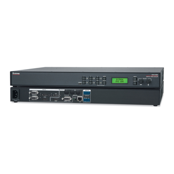
Page 15: Rear Panel Connections
Rear Panel Connections This section describes how to connect cables to a DVS 605 scaler. Rear Panel Cabling The illustration below shows all the possible rear panel features of the audio (DVS 605 A and DVS 605 AD) and the non-audio (DVS 605 and DVS 605 D) models. DVS 605 INPUT OUTPUTS... - Page 16 Power input (see figure 1 on page 7) — Connect the standard IEC power cord from a 100 to 240 VAC, 50-60 Hz power source into this connector. The front panel control and input selection buttons light in sequence during power-up. Inputs 1 and 2 —...
- Page 17 ATTENTION: • Do not overtighten the connector mounting screw. The shield it fastens to is very thin and can easily be stripped. • Ne serrez pas trop la vis de montage du connecteur. Le blindage auquel elle est attachée est très fin et peut facilement être dénudé. The LockIt bracket can also be used in a stacked formation, as shown below.
- Page 18 Audio output (fixed) figure 1 (audio models only) (see on page 7) — Connect audio output devices to this 5-pole, captive screw connector for line level, balanced or unbalanced, analog stereo. Wire the connectors as shown below. No Ground Here Ring Sleeves Sleeves Ring Do not tin the wires!
- Page 19 RS-232 and IR port (see figure 1 on page 7) — For serial RS-232 control, connect a host computer or control system to the 5-pole captive screw connector. This port is also a hard wired IR control for use with an external IR controller. The default RS-232 protocol is 9600 baud, 1 stop bit, no parity, 8 data bits, no flow control.
-
Page 20: Operation
Operation This section of the manual discusses the operation of a DVS 605 device. Topics covered include: • Front Panel Overview • Powering Up • DVS 605 Menu System — Configuration and Adjustments • Front Panel Lockout (Executive Modes) Window vs. Image Size and Position — An Overview •... -
Page 21: Powering Up
Powering Up When applying power to the DVS 605, the unit undergoes a start-up self-testing sequence (see image below) and then the LCD displays the default display cycle. Default Display Cycle When in use but not in any menu mode, the LCD screen defaults to cycling through the input and output configuration currently installed. -
Page 22: Menu Overview
Menu Overview After start-up, when no adjustments are actively being made, the “default cycle” appears on the LCD. The screens cycle between the number and video format of the active input and the current output resolution. Pressing the Menu button once brings up the first of eight main (top level) menus, as shown in figure 9. - Page 23 Figure 10. Main Menu DVS 605 • Operation...
-
Page 24: User Presets
To return to the default cycle from within any menu, press the Menu button repeatedly until the Exit menu appears, then press the Next button. Alternatively, allow the DVS 605 to time-out (after 20 seconds). Submenus are accessed from a main menu by pressing the Next button. When within a submenu, press the Menu button to go out of the submenu and back to the active main menu. -
Page 25: Input Configuration
Input Configuration This menu allows the user to adjust various input configuration settings such as video signal type, film mode, horizontal and vertical start position, horizontal and vertical active pixels, total pixel number, phase, HDCP Authorization, and EDID settings for the selected input. The selected input is shown as on the LCD screen images. -
Page 26: Output Configuration
Output Configuration The output configuration menu allows selection of output resolution and refresh rates, analog output types (RGBHV, RGBS, RGsB and Y, B-Y, R-Y), sync polarity, HDMI format, HDCP notification display, genlock setting, and offset values. Next Next Next Next RESOLUTION VGA FORMAT SYNC... - Page 27 When a new custom rate has been captured or uploaded, the on-screen display (OSD) dynamically updates with the new rate for that custom slot. For example if a custom 480p EDID is uploaded to slot C1, the LCD would read C1: 720x480. These five custom slots are shared between custom output resolutions (based on preferred timings 1 block) and custom EDID tables, which can be assigned to any DVS input.
- Page 28 HDCP status: inputs and outputs Through a series of SIS commands (see SIS Communication and Control) or using PCS (see Product Configuration Software starting on page 61) the DVS 605 has the ability to report HDCP status of the HDMI input signals as well as connected HDMI sink devices. When the unit is queried, it reports feedback on the specified input (source) or output (sink) as follows: •...
- Page 29 SDI Genlock (SDI models only) — This locks the output vertical refresh rate to the • applied analog genlock input on the SDI models. In the SDI Genlock mode, the output resolution and refresh rate of the DVS 605 must be set to exactly match the applied analog genlock signal to ensure a true genlock to the applied SDI Genlock signal.
-
Page 30: Audio Configuration (All Models)
Audio Configuration (All Models) Audio Configuration allows the user to set analog audio volume level (-100 dB to 0 dB range), turn audio mute on or off, adjust input gain and attenuation levels (–53 dB to +24 dB range) for the current analog input. It also allows selection of an input audio format (none, analog, 2-channel digital, full digital, 2-channel auto, or full auto), and the audio output type (stereo or dual mono), which can be adjusted for each input. -
Page 31: Advanced Configuration
Audio delay setting The DVS automatically delays all analog and digital audio inputs to compensate for internal video processing delay. Occasionally additional audio delay is required to account for other signal processors, scalers, or display devices in a system. For these situations, the DVS 605 offers an additional 0-255 millisecond static global audio delay which can be set via SIS Audio delay (available on all models) Output... - Page 32 Aspect Ratio Use either Adjust knob ([ {) to set the aspect ratio to Fill or Follow. The aspect ratio setting is per input, and allows the user to select a new aspect ratio for each input signal filling the entire output raster (using Fill, the default setting). For each input rate to be displayed with its native aspect ratio, use Follow (4:3, 5:4, 15:9, 16:9, 16:10).
- Page 33 Overscan Use the horizontal Adjust knob ([) to select input video type (RGB, YUV, RGBcvS, S-video, composite, or HDMI), and the vertical Adjust knob ({) to select the overscan mode (none, 2.5% or 5.0%). Overscan is specific to each input signal type. This zooms and crops SMPTE inputs to mask edge effects and ancillary data that are common in broadcast signals.
-
Page 34: View Comm Settings
Temperature This is a read-only menu that gives the internal temperature (degrees Celsius and Fahrenheit) of the connected device. No adjustments can be made. Factory Reset This menu allows the user to reset the device to the factory default settings. Press and hold the Auto button until the LCD display reads RESETTING, then release the Auto button. -
Page 35: Front Panel Lockout (Executive Modes)
Front Panel Lockout (Executive Modes) To prevent accidental changes to settings, press the Menu and Next buttons simultaneously for 2 seconds to enable front panel lockout mode (executive mode 2). The menu system returns to the default menu within 10 seconds. Executive mode 2 locks all front panel functions except input switching, PIP enable and PIP swap, and Auto-Image. -
Page 36: Window Vs. Image Size And Position - An Overview
Window vs. Image Size and Position — An Overview The DVS 605 provides users the ability to adjust a window size and position and the image (the content) size and position independently with regards to the output raster. This independent control is available for both the Main and PIP windows, allowing the user comprehensive flexibility in output configurations. -
Page 37: Picture-In-Picture (Pip) Mode
Picture-in-Picture (PIP) Mode The DVS 605 can display two images on the screen simultaneously. The PIP window can be activated using front panel PIP button, by discrete SIS commands Picture in Picture Size and Position (see on page 42), by PIP presets, by PCS (see Page on page 86), or the embedded web pages (see PIP Settings Page... -
Page 38: Pip Presets
PIP Presets A PIP preset contains settings for the size and position of the PIP window and which main and PIP inputs that were active when the preset was saved. PIP presets are used to quickly recall a group of settings that relate to the main and PIP windows and content settings. Sixteen global PIP presets are available for the DVS 605. -
Page 39: Other Dvs 605 Operating Features
Other DVS 605 Operating Features Screen Save Screen Save mode allows the user to configure what is displayed on the video output, and for what duration, when the selected DVS 605 input loses an active video signal. By default, the DVS 605 continues to output muted (black) video and sync indefinitely. Alternatively, users have the ability to display a blue screen with a moving text bug that indicates that there is no active signal on the selected DVS 605 input. -
Page 40: The Osd Bug
Audio Format Audio Source Analog Input Digital Inputs EDID None Muted No CEA Analog 5-Pole Captive No CEA LPCM-2Ch Embedded Digital LPCM-2Ch CEA Multi-Ch Embedded Digital Multi-Ch CEA LPCM-2Ch Auto Embedded Digital LPCM-2Ch CEA (when present), else 5-Pole Captive Multi-Ch Auto Embedded Digital Multi-Ch CEA (when present), else... -
Page 41: Resetting The Unit
Resetting the Unit There are three unit reset modes (numbered 1, 4, and 5), These are available by pressing the recessed Reset button on the rear panel with a pointed stylus, pen, or similar item to access it. The following table gives a summary of the reset modes. ATTENTION: Review the reset modes carefully. -
Page 42: Sis Communication And Control
When a local event such as a front panel selection or adjustment takes place, the DVS 605 scaler responds by sending a message to the host. No response is required from the host. Example scaler-initiated messages are listed here. ] © Copyright 2015, Extron Electronics, DVS 605, V • x.xx 60-1059-01] Tues, 17 February 2015 11:27:33 ] The DVS 605 sends the copyright message when it first powers on. -
Page 43: Password Information
Password Information Password: prompt requires a password (administrator level or user level) followed by a carriage return. The prompt is repeated if the correct password is not entered. NOTE: The factory configured passwords for all accounts on this device have been set to the device serial number. -
Page 44: Symbol Definitions
Symbol Definitions • = Space Carriage return with line feed | or } = Carriage return with no line feed or W = Escape 14, 24, 28 Superscripts indicate the error message displayed if the command is entered incorrectly or with invalid parameters (see Error response references on the previous page). - Page 45 Image or window number: 1 = Main window 2 = PIP window Scaler resolution and EDID emulation: 0 = Automatic: match current output resolution (default for EDID emulation) LCD reads Match Output 1 = Output 1 (analog VGA connector, available for Save and Export EDID commands only) 2 = Output 2 (HDMI connector, available for Save and Export EDID commands only) 3 = Custom EDID/output rate 1...
- Page 46 Test patterns: 0 = Off (default) 8 = Ramp 1 = Crop 9 = White field 2 = Alternating pixels 10 = 1.33 aspect ratio 3 = Alternating lines 11 = 1.78 aspect ratio 4 = Crosshatch 12 = 1.85 aspect ratio 5 = 4x4 crosshatch 13 = 2.35 aspect ratio 6 = Color bars...
- Page 47 Video switching duration, from 2 (0.2 sec) to 50 (5.0 sec). Default value is 3 or 0.3 sec HDMI output format: 0 = Auto (based on sink EDID), default 1 = DVI 2 = HDMI 444 RGB 3 = HDMI 444 YUV “FULL” 4 = HDMI 444 YUV “LIMITED”...
- Page 48 X4& Input signal or SDI genlock 0 = Disabled, (default) 1 = Input signal genlock enabled, locks output vertical rate to selected input vertical rate 2 = SDI genlock enabled, locks output vertical rate to applied genlock input (“D” models only) Input signal and genlock status 0 = Input signal or SDI genlock disabled...
- Page 49 X12! Password (Maximum length of 128 alphanumeric characters, spaces, and symbols. Cannot start with a space.) NOTES: • A user password cannot be assigned if no administrator password exists, the E14 error code is returned. If the administrator password is cleared, the user password is also removed.
-
Page 50: Sis Command And Response Table
SIS Command and Response Table Command ASCII Command Response Additional Description (host to scaler (scaler to host Input selection In X!•All] Video and audio Select video and audio from input In X!•RGB] Video X!& Select video from input source In X!•Aud] Audio Select audio from input source View video input... - Page 51 Command ASCII Command Response Additional Description (host to scaler (scaler to host Input name Write input name NmiX!,X1$] EX!,X1$NI} Set the name for input Read input name X1$] X1$. EX!NI} View input name NOTE: To clear an input name, a single space character should be entered for X1$. This resets the input name to the default value. = Input selection: 1 to 5 KEY: = Text label or preset name, up to 16 characters...
- Page 52 Command ASCII Command Response Additional Description (host to scaler (scaler to host Auto-Image ImgX!*1] Enable X!*1A Activate Auto-Image for input ImgX!*0] Disable X!*0A Turn Auto-Image off for input View status View Auto-Image setting. Img0] Execute Execute an Auto-Image to the selected input (follows current aspect setting).
- Page 53 Command ASCII Command Response Additional Description (host to scaler (scaler to host Total pixels (available only for RGB and YUV auto input signals) TpixX!*X^] Specify a value EX!*X^TPIX} Adjust the total pixels to specified value input Increment value TpixX!*X^] Increase the total pixels. EX!+TPIX} Decrement value TpixX!*X^]...
- Page 54 Command ASCII Command Response Additional Description (host to scaler (scaler to host Color ColrX!*X1%] Set a specific value EX!*X1%COLR} Set color level to for input ColrX!*X1%] Increment value Increment color level. EX!+COLR} ColrX!*X1%] Decrement value Decrement color level. EX!-COLR} View EX!COLR} X1%] View current setting for input...
- Page 55 Command ASCII Command Response Additional Description (host to scaler (scaler to host Horizontal size (window) Specific value Hsiz1*X1**X1&] E1*X1**X1&HSIZ} X1& X1*. Set horizontal sizing to for window Increase size Hsiz1*X1**X1&] Widen the window. E1*X1*+HSIZ} Decrease size Hsiz1*X1**X1&] Make the window narrower. E1*X1*-HSIZ} View E1*X1*HSIZ}...
- Page 56 Command ASCII Command Response Additional Description (host to scaler (scaler to host Output Configuration Output scaler rate Set output rate RateX1(] Select output resolution and refresh rate. EX1(RATE} View output rate Show selected output rate. ERATE} X1(] figure 27 KEY: = Scaler resolution/EDID emulation: (see the EDID table, on page 37 for full details).
- Page 57 Command ASCII Command Response Additional Description (host to scaler (scaler to host Audio Configuration Audio mute (global settings) Amt1] Mute on Mute selected input. Amt0] Mute off Un-mute selected input. View status View mute status. KEY: X( = Enable/disable: = mute off, = mute on Analog audio gain and attenuation (audio models only: per analog input) AudX4)]...
- Page 58 Command ASCII Command Response Additional Description (host to scaler (scaler to host Audio input format NOTES: • Selects between analog (5-pole captive screw) or digital (embedded in HDMI input) audio sources. • Inputs 1 and 2 can only be set to or 1;...
- Page 59 Command ASCII Command Response Additional Description (host to scaler (scaler to host Input presets 2*X2$. 2RprX2$] Recall preset Recall input preset for selected input. 2*X2$, 2SprX2$] Save preset Save input preset for selected input. PrstX2*X2$] Delete/clear preset EX2*X2$PRST} Clears input preset , and sets input preset name to unassigned...
- Page 60 Command ASCII Command Response Additional Description (host to scaler (scaler to host Advanced Configuration Test pattern Set test pattern TestX2)] EX2)TEST} X2). Set the test pattern to View test pattern ETEST} X2)] X2). View the current test pattern = Test patterns: KEY: 0 = off (default) 4 = crosshatch...
- Page 61 Command ASCII Command Response Additional Description (host to scaler (scaler to host Video effect Swef0] E0SWEF } Sets the switch to cut. Dissolve Swef1] Sets the switch to dissolve. E1SWEF} (or 1]) View setting ESWEF} View setting ( = cut, = dissolve [default]).
- Page 62 Command ASCII Command Response Additional Description (host to scaler (scaler to host HDCP input authorization (valid for HDMI inputs only) HdcpEX!*1] HDCP Authorized Turn HDCP Authorized device on for EEX!*1HDCP} device on input (default). HDCP Authorized HdcpEX!*0] EEX!*0HDCP} Turn HDCP Authorized device off for input device off HDCP Authorized Query HDCP Authorized device status for input...
- Page 63 Command ASCII Command Response Additional Description (host to scaler (scaler to host Video signal presence View signal presence Signal status for input 1*2*3*4*5. X4$*X4$*X4$*X4$ = no input, = input detected. *X4$] KEY: = Video signal status: 0 = video or TMDS signal not detected, 1 = video or TMDS signal detected Hardwired IR port 65*0# IRDisable0]...
- Page 64 Command ASCII Command Response Additional Description (host to scaler (scaler to host Information request VidX!•AudX!•VtypX#•StdX1)•BlkX3!•HrtX1#•VrtX1#•PipX!] General information NOTES: • response is a “-” on the non audio model. “Vtyp” returns the detected input type (X!*\). • response is “ ” unless video is muted, then the response is “ ”.
-
Page 65: Sis Command And Response Table For Ip Control Port
DVS 605 • SIS Communication and Control... - Page 66 DVS 605 • SIS Communication and Control...
- Page 67 DVS 605 • SIS Communication and Control...
- Page 68 DVS 605 • SIS Communication and Control...
-
Page 69: Product Configuration Software
Product Configuration Software The Extron Product Configuration Software (PCS version 3 or later) offers another way to configure the DVS 605 via USB or TCP/IP connection in addition to the SIS commands. This section describes the software installation and communication. For in operation configuration information see the DVS 605 Product Configuration Software help file. -
Page 70: Starting The Software
On the Extron website, mouse over the Download tab (see figure 29, on the previous page). From the drop-down menu, click the PCS Product Configuration Software link ( On the PCS page, click the Download button (see figure 30, Figure 30. PCS Download Enter any required information to start the download. -
Page 71: Tcp/Ip Panel
To edit communication settings from the Device Discovery panel: In the Device Discovery panel, click the Edit button of the desired device. The Communication Settings dialog box opens. 0.0.0.0 Figure 32. Communications Settings Dialog Box Enter the relevant details for each field or select the DHCP checkbox (see figure 32, Ethernet Settings on page 118 for configuration details). -
Page 72: Offline Device Preview
In the Telnet Port field (see figure 33, on the previous page), enter the Telnet port of the desired device. Click the Connect button ( ). A new device tab opens. Offline Device Preview It is possible for the DVS 605 pages to be viewed without connecting directly to a device, but the page settings cannot be changed or saved. -
Page 73: Using The Software
Using the Software NOTE: For detailed software navigation, open the DVS 605 Product Configuration Software Help file from the Device Menu (see figure 37 on the next page). When connected to an online device, a connection status icon (circle) shows green on the device name tab (see figure 36, The configuration page has a global navigation bar (ribbon) ( ) from which each of the... -
Page 74: Device Menu
Device Menu The Device drop-down menu contains options for disconnecting, changing hardware and communication settings, resetting the device, backing up and restoring device configurations, updating firmware, and viewing software module information. Figure 37. Device Menu Disconnect This option disconnects the PCS program from the connected device and closes the device tab. - Page 75 To change hardware settings: Select the applicable tab (Device Name , Date and Time , or Password , see figure 38 on the previous page). Complete the fields as desired. NOTE: For date and time settings, the device can be synced to the PC settings by clicking the Sync to PC button.
- Page 76 Reset Device This option contains selectable reset modes for resetting the connected device. From the Device drop-down menu, select Reset Device...(see figure 37, on page 66). The Reset Device dialog box opens. Figure 40. Reset Device Dialog Box To reset the device select the applicable radio button and click the Reset button (see figure 40, Clicking the Close button ( ) closes the dialog box without resetting the device (see...
- Page 77 In the Backup window, browse to a location on the connected PC in which to save the configuration. Alternatively, allow the device to save the file to the default folder. Rename the file as desired, click Save, and allow the process to complete. The file is saved with a .extz extension.
- Page 78 In the Open Backup File window, browse to where the saved backup configuration is stored. Select the applicable configuration file (with a .extz extension) and click Open. On the Restore This Device dialog box, click Restore (see figure 42, on the previous page) to upload the file to the connected DVS 605.
- Page 79 Click the Open Backup File button ( ) on the Restore To Multiple Devices dialog box. An Open Backup File window opens. In the Open Backup File window, browse to the saved backup configuration. Select the applicable configuration file (with a .extz extension) and click Open. In the Restore to Multiple Devices dialog box, click Restore (see figure 44, on the previous page) to upload the file to the listed DVS 605 devices.
- Page 80 To add devices to the list: Enter the IP address, Password, Telnet port details in each field for a desired target device (see figure 46, NOTE: The factory configured passwords for all accounts on this device have been set to the device serial number. In the event of a complete system reset, the passwords convert to the default, which is no password.
- Page 81 Help This option contains a link to the device-specific help file. From the Device drop-down menu, select device-specific Help (see figure 37 page 66, ). The help file opens in a separate window. Figure 47. Extron DVS 605 Help Window About This Module This option contains the device module part number and current version and build number.
-
Page 82: Av Controls Panel
AV Controls Panel The AV Controls panel can be used to switch inputs, set breakaway audio, enable or disable PIP, view active input and output status, start an Auto-Image instance, freeze the displayed image, and mute or unmute video and audio signals. Included in the panel is a summary of the current active input and output status, including signal format and HDCP status, as well as AFL status. - Page 83 Auto-Image button Clicking the Auto-Image button (see figure 49, on the previous page) starts a one-time Auto-Image on the currently selected input. Freeze button Clicking the Freeze button ( ) freezes the current displayed video frame for the currently selected input. When the button is blue the image is frozen. Click the button again to unfreeze the image.
-
Page 84: Configuration Pages
Configuration Pages The configuration pages contain options for input and output configuration, EDID management, image settings, image size and position, audio configuration, and general device settings. Each page is accessible via the global navigation bar. Figure 50. Global Navigation Bar Input and Output Configuration Page Click the Input/Output Config icon to open this page. - Page 85 Auto-Image Select the Auto-Image checkbox (see figure 51, on the previous page) for any input to enable an automatic Auto-Image on that input. When enabled, Auto-Image is applied whenever there is a change in the input sync. Auto-Image attempts to size and center the input signal based on the aspect ratio setting.
- Page 86 Output Configuration panel The Output Configuration panel contains controls for output resolution and rate, analog output format and sync polarity setting, digital output format, switch transitions, Accu-RATE frame lock settings, and available test pattern selection. Figure 52. Output Configuration Resolution From the Resolution drop-down menu (see figure 52, ), select the applicable output resolution.
- Page 87 Genlock/Accu-RATE frame lock (AFL) From the Genlock/Accu-RATE Frame Lock panel (see figure 52, on the previous page), select one of the following radio buttons: Off — Frame lock is disabled. • • SDI Genlock — Frame lock enabled and set to SDI input. Input AFL —...
-
Page 88: Edid Minder Page
EDID Minder Page EDID Minder is an EDID management process that manages the EDID information between the scaler and one or more input sources. Click the EDID Minder icon (see figure 54, on the global navigation bar to open the EDID Minder page. Figure 54. - Page 89 To assign EDID to all inputs: From the Favorites, Connected Outputs, or Available EDID pane (see figure 54, on the previous page), select an EDID. From the inputs group box, click the Assign to All button ( NOTE: Unchecked inputs are ignored when assigning an EDID to all inputs. To match the selected inputs to the current output resolution: Matching the output resolution is the default value for all inputs.
-
Page 90: Image Settings Page
Image Settings Page From this page, signal sampling and picture control settings can be adjusted, user and input presets can be saved and recalled, and overscan settings can be applied. In addition an Auto-Image, an Auto-Image and Fill, or an Auto-Image and Follow can be triggered. Click the Image Settings icon (see figure 55, ) on the global navigation bar to open the Image Settings page. - Page 91 To automatically adjust these settings, perform one of the following: • Click the Auto-Image button (see figure 56, on the previous page)) to perform a one-time Auto-Image. • Click the Auto-Image & Fill button ( ) to perform a one-time Auto-Image and fill the entire video output (ignores aspect ratio setting).
- Page 92 Presets panel Presets save output settings to be recalled through RS-232 or Ethernet (see the table below for a comparison of saved settings for input and user presets). Figure 59. Input and User Presets Panel Settings Included Within Presets Setting User Preset Input Preset Horizontal and Vertical Start...
- Page 93 Input presets There are 128 presets that are global to all inputs. The presets contain all of the settings for an input when used with an upstream matrix switcher. Input presets save signal type, signal sampling, and picture control settings. To save an input preset: From the Input Presets list (see figure 59, on the previous page), select the...
-
Page 94: Size And Position Page
To clear a preset: From the User Presets list (see figure 59, on page 83), select the desired preset. Click the Clear button ( ). The Presets dialog box opens. Click the Clear button to erase saved data. Click the Cancel button to return to the Image Settings page. - Page 95 To adjust the size and position automatically: To automatically adjust these settings, perform one of the following: • Click the Auto-Image button (see figure 60, on the previous page) to perform a one-time Auto-Image. • Click the Auto-Image & Fill button ( ) to perform a one-time Auto-Image and fill the entire video output (ignores aspect ratio settings).
-
Page 96: Audio Configuration Page
Audio Configuration Page From the Audio Configuration page, audio inputs and outputs can be configured. Click the Audio Configuration icon (see figure 63, ) on the global navigation bar to open the Audio Configuration page. Figure 63. Audio Configuration Page For inputs 1 and 2, available formats include: •... - Page 97 Input gain The Input Gain fader (see figure 63, on the previous page) can be applied to analog inputs. It has a gain range of -53 dB to +24 dB. Adjustments are applied in 0.1 dB increments. The default setting is 0.0 dB. The current Gain level ( ) for each input is displayed to the right of the corresponding Audio Format drop-down menu.
-
Page 98: General Settings Page
General Settings Page The General Settings page allows the user to set a screen saver, select HDCP notification and HDCP Mode options, set the front panel lockout mode (Exec Mode), enable on-screen input information, and enable or disable auto input selection and IR control. In addition, it gives access to the Hardware Settings page. -
Page 99: Software Menu
To set the front panel lockout mode, click the applicable Front Panel Lockout (Exec Mode) radio button (see figure 64, on the previous page) as desired. • Unlock Front Panel • Mode 1: Lock Front Panel • Mode 2: Limit Front Panel to Input Selection, Auto-Image, PIP and Swap To enable on screen display (OSD) selection, check the Enable On Screen Display (OSD) checkbox (... - Page 100 Figure 67. Software Settings Dialog Box Click the Re-enable Confirmation Dialogs button (see figure 67, ). The dialog box closes and the reset is complete. Click the Close button ( ) to close the dialog box without re-enabling the confirmation dialogs. Tutorial This option displays a general overview of where to find features in the PCS framework.
- Page 101 About Extron PCS This option contains information about the current PCS version. From the Software menu, select About Extron PCS (see figure 65, page 91). The About - Extron PCS dialog box opens. Figure 70. About - Extron PCS Dialog Box Click the Details button (see figure 70, ) for more information about the software and embedded modules.
-
Page 102: Using The Default Web
Using the Default Web Pages The DVS 605 features an internal web server, displayed as a set of default web pages. These pages allow you to configure and operate the DVS 605 unit via a LAN or WAN connection through the RJ-45 port, using a web browser such as the Microsoft Internet ®... -
Page 103: Turning Off Compatibility Mode
Turning Off Compatibility Mode The DVS 605 default web pages do not support compatibility mode in Microsoft Internet Explorer. To check compatibility view settings: From the Tools menu of the browser, select Compatibility View settings. The Compatibility View Settings dialog box opens. Be sure that the Display intranet sites in Compatibility View checkbox is cleared, and that the IP address of the DVS 605 is not in the list of web sites that have been added to Compatibility View. -
Page 104: Configuration Pages
Configuration Pages NOTE: From Hardware pages, click the Configuration tab The Configuration pages options are: Input/Output Config • EDID Minder • Image Settings • PIP Settings • Audio Config • Preset Management • Device Settings • Figure 73. Global Navigation Bar for the Configuration Page The browser screen is set out as two sections. - Page 105 Auto-Image button Click this button (see image on the right, ) to start a one time Auto-Image on the currently selected input. AV input buttons (inputs 1-5) Click these buttons ( ) to select an input as desired. As a new one is selected, the summary text within the panel changes to reflect the new input and output status.
-
Page 106: Input/Output Configuration Page
Input/Output Configuration Page Click this button to open to this page. This page has Input Configuration and Output Configuration panels. Input Configuration panel The Input Configuration panel consists of user configurable fields for each of the five inputs. These include: input naming, signal type, aspect ratio, Auto-Image, Auto Memory, HDCP Authorized status, and film detection. - Page 107 Aspect ratio Select Fill or Follow from the drop-down menu (see figure 75, on the previous page) to set the aspect ratio. Fill — The input signal is scaled to fill the entire video output. • • Follow — Follows the signal aspect ratio, with respect to the current output resolution setting.
- Page 108 Output Configuration panel The right panel consists of user configurable fields for video outputs. These include: output resolution, refresh rate, signal format and sync polarity for the analog output, and signal format for the digital output. The switch transition mode between inputs can be set, and a test pattern selection is available for use in calibrating a connected display.
- Page 109 Digital output signal format Click the arrow and from the drop-down menu box (see figure 76, on the previous page) select an applicable signal format. Selectable formats are: Auto (based on sink/display EDID) • • HDMI RGB • • HDMI YUV 444 Full •...
-
Page 110: Edid Minder Page
EDID Minder Page Extron EDID Minder is an EDID management process that automatically manages the EDID information between a digital display device and one or more input sources. Click this button to open the EDID Minder page. From this page an EDID data set can be assigned to any input with an Auto-Detect, an RGB, or an HDMI/DVI input type. - Page 111 Assigning EDIDs To assign EDID to selected inputs: From the Inputs screen (table of inputs) on the right, select the desired input or inputs (see figure 78, From the Favorites, Connected Outputs, or Available EDIDs panels, select an available EDID ( represented by a blue, green, or yellow output display icon).
-
Page 112: Image Settings Page
Image Settings Page From this page signal sampling and picture control settings can be set, user and input presets can be saved and recalled, and overscan settings can be applied. Click this button to open the Image Settings page. Figure 79. Image Settings Page Signal Sampling In this panel (see figure 79,... - Page 113 Picture Control This panel shows the Image Settings for the selected input (see figure 79, , on the previous page). These include brightness, contrast, color, tint, and detail, which can be adjusted and applied to that input. To adjust the picture settings click and drag the associated slider for any image setting (brightness, contrast, color, tint, or detail) to the desired value.
- Page 114 Input Presets A total of 128 global input presets are available for the DVS 605. An input preset is a user-defined set of input and picture control settings that can be saved for each source within a system so that they can be recalled whenever the source is applied. Input presets are unique to the signal that was applied when the preset was initially saved.
-
Page 115: Pip Settings Page
PIP Settings Page In PIP mode, the DVS 605 can display two images on the screen simultaneously. From this page, the PIP settings can be adjusted. This includes input selection, swapping between the main and PIP inputs, adjustment of the picture control settings, main and PIP window position and sizing, and the saving and recalling of PIP presets. - Page 116 PIP picture controls These PIP input settings include brightness, contrast, color, tint, and detail. NOTES: Picture controls are not applied if there is no input signal. Any changes made • while there is no input signal are lost when a signal is detected. •...
- Page 117 PIP presets Sixteen global PIP presets are available for the DVS 605 (see figure 81 on page 107). A PIP preset contains settings for the size and position of PIP. It also contains the main and PIP inputs that were active when the preset was saved. By default, the first ten PIP presets have settings already associated with them, but they can be overwritten (see figure 82).
-
Page 118: Audio Settings Page
Audio Settings Page Using this page, each of the audio inputs can be configured, including setting the input format and the gain (for analog inputs). Also analog audio output format can be set and adjusted. NOTES: • Audio inputs 1 and 2 are disabled for DVS 605 and DVS 605 D models. They do not support analog audio. - Page 119 Click and drag the handle of the Gain fader, click the up and down arrows in the field below the fader, or enter a value in the field (see figure 83, on the previous page). NOTES: • You can only adjust the gain and attenuation for an input that is in analog or Auto format.
-
Page 120: Preset Management Page
Preset Management Page This Preset Management page gives access to assigned input presets (see figure 84, ), user presets ( ), and PIP presets ( ). Each preset can be renamed, recalled, or cleared. A brief description of the settings contained within each preset type is given at the top of each list. -
Page 121: Device Settings Page
To rename a preset: Select the input preset ( ), user preset ( ), or PIP preset ( ) that is to be renamed. Click Rename (see figure 84, on the previous page). The cursor moves into the Name field. In the Name field, enter a unique name for the selected preset. Press <Enter>... - Page 122 To set audio to follow the PIP input, select the Audio Follows PIP checkbox (see figure 85, on the previous page). To set audio to follow the main input, clear the Audio Follows PIP checkbox . To disable IR control, select the Disable IR Control checkbox ( To re-enable IR control, clear the Disable IR Control checkbox.
- Page 123 Mute Video and Sync When enabled, this option allows a connected display (sink) to go into power saving (standby) state when no signal is present (see figure 85 on page 113, To enable this option, click the Mute Video and Sync button. The button turns blue to indicate the option is active.
-
Page 124: Hardware Pages
Hardware Pages Click the Hardware tab to open these pages. The Hardware page options are: • Unit Information Device Name • • Connection • Firmware Loader Exec/Power Mode • • Date and Time • Password • Reset Device Figure 86. Global Navigation Bar for the Hardware Pages Unit Information Page This page gives a non-configurable view of information about the connected unit. -
Page 125: Device Name Page
Device Name Page This page allows the user to assign or change the connected device name. Click this button to open the page. Figure 88. Device Name Page To assign or change the name: Enter a name for the device in the name field (see figure 88, ). -
Page 126: Firmware Loader Page
RS-232 Settings To configure the RS-232 settings (see figure 89, on the previous page): From the Baud Rate drop-down menu, select the appropriate baud rate. From the Stop Bits drop-down menu, select the number of bits used to indicate a byte. From the Bits drop-down menu, select the number of data bits to transmit. -
Page 127: Executive/Power Mode Page
To update the device firmware: on the previous page). The Choose File to Upload Click Browse (see figure 90, window opens. Browse to and select the firmware file to upload to the device. Valid firmware files have an EFF or ESF extension. NOTE: Current firmware updates can be downloaded onto your PC from the Firmware Download Center page of the Extron website. -
Page 128: Date And Time Page
Power Mode The low power-standby state disables all video input processing and all video outputs to save energy when the DVS 605 is not in use. To set the power mode (see figure 91, on the previous page): Click the radio button for the desired power mode (Full Power or Low Power - Standby State). -
Page 129: Password Page
Password Page This page allows the user to change an administrator and user password on the device. Click this button to open the page. Figure 93. Password Page Administrators and users can view any setting on the device. Administrators have the ability to make adjustments to any setting. -
Page 130: Reset Device Page
Reset Device Page This page allows the user to reset the device. Click this button to open the page. Figure 94. Reset Device Page There are three reset options available (see figure 94, • Reset scaler settings to default (Retains IP) •... -
Page 131: Mounting
Mounting This section describes: Tabletop Placement • • Rack Mounting • Furniture Mounting If the DVS 605 is to be rack mounted, it is important to mount it before cabling it. Four rubber feet are included with the unit. Install the feet only if the unit is to be mounted on a tabletop (see Tabletop Placement below). -
Page 132: Rack Mounting The Dvs 605
Each Side UTM 100 #8 Screw Mounting Bracket (4) Places MBU 149 Attach the UTM 100 to Each Side Mounting Bracket the rack ear, using the provided screws. Figure 96. Furniture Mounting the DVS 605 DVS 605 Series • Mounting... -
Page 133: Extron Warranty
Extron Warranty Extron warrants this product against defects in materials and workmanship for a period of three years from the date of purchase. In the event of malfunction during the warranty period attributable directly to faulty workmanship and/ or materials, Extron will, at its option, repair or replace said products or components, to whatever extent it shall deem necessary to restore said product to proper operating condition, provided that it is returned within the warranty period, with proof of purchase and description of malfunction to: USA, Canada, South America,...
Need help?
Do you have a question about the DVS 605 Series and is the answer not in the manual?
Questions and answers