Table of Contents
Advertisement
Quick Links
Advertisement
Table of Contents
Troubleshooting

Subscribe to Our Youtube Channel
Related Manuals for Extron electronics DVS 150


Summary of Contents for Extron electronics DVS 150
- Page 1 DVS 150 Digital Video Scaler 68-459-01 Printed in the USA...
- Page 2 Precautions Safety Instructions • English This symbol is intended to alert the user of important operating and maintenance (servicing) instructions in the literature provided with the equipment. This symbol is intended to alert the user of the presence of uninsulated dangerous voltage within the product's enclosure that may present a risk of electric shock.
- Page 3 Quick Start — DVS 150 Installation Step 1 Install the four rubber feet on the bottom of the scaler (1A), or mount the scaler in a rack (1B). Step 2 Turn off power to the input and output devices, and unplug their power cords.
- Page 4 H-SYNC — Change the polarity of the horizontal sync signal to allow any projector to distinguish the DVS 150 input from a standard RGB input. +: Sets the horizontal sync polarity to positive. -: Sets the horizontal sync polarity to negative.
-
Page 5: Table Of Contents
Installing the software ... 4-5 Using the software ... 4-6 Chapter 5 • Troubleshooting Operating Problems ... 5-2 ... 1-1 ... 2-5 ... 2-6 ... 3-2 ... 4-1 ... 4-2 ... 4-3 ... 4-5 ... 5-1 DVS 150 Table of Contents... - Page 6 Table of Contents, cont’d Appendix • Reference Information Specifications ... A-2 Part Numbers ... A-3 DVS 150 part numbers ... A-3 Related part numbers ... A-3 BNC cables ... A-3 ... A-3 Bulk cable Assorted connectors ... A-4 Precut cables DVS 150 Table of Contents ...
-
Page 7: About The Scaler
DVS 150 Chapter One Introduction About the Scaler Features... -
Page 8: About The Scaler
LCD (liquid crystal display) projector, DLP (digital light processing) projector, or plasma display. The DVS 150 includes a 15-pin HD RGB pass-through connector for RGB input. Video signals coming into the scaler from this connector are not scaled. Instead, they are passed directly to the outputs. - Page 9 • Software-based configuration — Allows you to configure the scaler through menu controls, simplifying installation. • Switchable sync polarities — Allow you to manually set the horizontal and vertical sync polarities, to allow the output device to store DVS input as a unique input. DVS 150 Introduction...
- Page 10 Introduction, cont’d DVS 150 Introduction...
-
Page 11: Chapter 2 • Installation
DVS 150 Chapter Two Installation Rear Panel Features Installation Front Panel Features Configuring the Scaler... -
Page 12: Rear Panel Features
Installation Overview To install and set up the DVS 150, follow these basic steps: If desired, mount the scaler in a rack (see “Mounting the scaler” on page 2-3). Otherwise, install the rubber feet (see “Installing the rubber feet” on page 2-3). -
Page 13: Mounting The Scaler
If you are not rack mounting the scaler, skip to “Installing the rubber feet” below. The DVS 150 can be rack mounted using one side of an optional 19” 1U Universal Rack Shelf (Extron part # 60-190-01). -
Page 14: Cabling
If you cable the scaler for sync on green (RGsB or SOG) output, you must also configure the scaler for SOG via the configuration menu. See “Configuring the Scaler” on page 2-6 for instructions. DVS 150 Installation Component Video (Input 2) -
Page 15: Front Panel Features
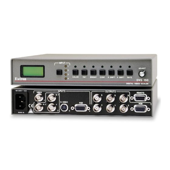
RGB connector. Front Panel Features Figure 6 — DVS 150 front panel LCD — Displays configuration menus and status information. See “Configuring the Scaler” on page 2-6 and “Adjusting an image” on page 3-2. -
Page 16: Configuring The Scaler
Negative. Vertical sync polarity (V-SYNC) — Changes the polarity of the vertical sync signal to allow any projector to distinguish the DVS 150 input from a standard RGB input. To toggle between Positive and Negative, turn the adjustment knob while the Vertical sync menu is displayed. - Page 17 Blue mode — Turns off the red and green video output to allow you to set up color and tint using a color bar pattern. To toggle between On and Off, turn the adjustment knob while the Blue mode menu is displayed. By default, blue mode is set to Off. DVS 150 Installation...
- Page 18 Installation, cont’d DVS 150 Installation...
-
Page 19: Chapter 3 • Operation
DVS 150 Chapter Three Operation Front Panel Operation... -
Page 20: Front Panel Operation
Push the control button that corresponds to the adjustment you want to make. The LED above the pressed button lights, and, depending on the selected button, the LCD displays the current level value for the adjustment. DVS 150 Operation 1280 X 1024 @60... -
Page 21: Choosing The Output Rate
Default • 640 x 480, 75 Hz • 800 x 600, 75 Hz • 832 x 624, 75 Hz • 852 x 480, 75 Hz • 1024 x 768, 75 Hz • 1280 x 1024, 60 Hz DVS 150 Operation... -
Page 22: Freeze Mode
To perform a system reset, press and hold the input button while attaching the AC SYSTEM RESET DVS 150 Operation activated only by issuing an RS-232 command (see chapter 4 for more information). If freeze mode is activated, the LCD screen displays the message displayed at the left. -
Page 23: Chapter 4 • Serial Communication
DVS 150 Chapter Four Serial Communication RS-232 Programmer’s Guide Remote Contact Closure Operation Control Software for Windows... -
Page 24: Rs-232 Programmer's Guide
The DVS-initiated messages are listed below (underlined). (C) Copyright 1999, Extron Electronics, DVS 150, Vx.xx The copyright message is initiated by the scaler when it is first powered on. Vx.xx is the firmware version number. -
Page 25: Dvs Error Response
(#) to the signal ground (pin 5). To force one of the inputs to be selected continuously, leave the short to signal ground in place. This will override any front panel input selection. DVS 150 Serial Communication... -
Page 26: Command/Response Table
Increment down Horizontal shift Specific value Increment up Hph+ Increment down Hph– DVS 150 Serial Communication ASCII to HEX Conversion Table = 1 = On, 0 = Off = Input type = Detail level DESCRIPTION Sets input source Selects color... -
Page 27: Control Software For Windows
Example response: Ver 3.2 Sets still mode On or Off Sets detail mode to level 1 (low), 2, or 3 (high) Displays the Extron part number •Tin •Con •Brt •Hph •Vph •Typ •Stl •Det DVS 150 Serial Communication •Rte •Frz... -
Page 28: Using The Software
• From within the Signal Enhancement Products Control Program, click on the Help menu on the main screen. • From within the Signal Enhancement Products Control Program, press the F1 key. DVS 150 Serial Communication the Signal Enhancement Products Control Pgm icon in the Extron Electronics group or folder. -
Page 29: Chapter 5 • Troubleshooting
DVS 150 Chapter Five Troubleshooting Operating Problems... -
Page 30: Troubleshooting
Troubleshooting, cont’d This section gives recommendations on what to do if you have problems operating the DVS 150, and it provides examples and descriptions for some image problems you might encounter. Following are some tips to help you in troubleshooting. - Page 31 The image is too soft. The detail level needs to be changed. Solution Switch to input 1–3. Input 4 is pass-through only (page 1-2). Turn off sync on green (page 2-6). Change the detail level (page 2-6). DVS 150 Troubleshooting...
- Page 32 Troubleshooting, cont’d DVS 150 Troubleshooting...
-
Page 33: Specifications
DVS 150 Appendix Reference Information Specifications Part Numbers... -
Page 34: Reference Information
Power ... 100VAC to 240VAC, 50/60 Hz, 30 Watts, internal, auto-switchable Temperature/humidity ... Storage -40° to +158°F (-40° to +70°C) / 10% to 90%, non-condensing Operating +32° to +122°F (0° to +50°C) / 10% to 90%, non-condensing DVS 150 Reference Information... -
Page 35: Part Numbers
Approvals ... UL, CUL, CE, FCC Class B MTBF ... 30,000 hours Warranty ... 2 years parts and labor Specifications are subject to change without notice. Part Numbers DVS 150 part numbers Extron Part DVS 150 Signal Enhancement Products Control Program DVS 150 User’s Manual S-video cable, 6’... -
Page 36: Assorted Connectors
BNC-5-75’ HR (75 feet/23.0 meters) BNC-5-100’ HR (100 feet/30.0 meters) BNC-5-150’ HR (150 feet/45.0 meters) BNC-5-200’ HR (200 feet/60.0 meters) BNC-5-250’ HR (250 feet/75.0 meters) BNC-5-300’ HR (300 feet/90.0 meters) DVS 150 Reference Information 100-074-51 100-075-51 100-076-51 26-210-04 26-210-05 26-210-06... -
Page 37: Fcc Class B Notice
This equipment has been tested and found to comply with the limits for a Class B digital device, pursuant to part 15 of the FCC Rules. These limits are designed to provide reasonable protection against harmful interference in a residential installation. This equipment generates, uses and can radiate radio frequency energy and, if not installed and used in accordance with the instructions, may cause harmful interference to radio communications. - Page 38 EXTRON ELECTRONICS, EUROPE EXTRON ELECTRONICS/RGB SYSTEMS, INC. Beeldschermweg 6C, 3821 AH Amersfoort 1230 South Lewis Street, Anaheim, CA 92805 +31.33.453.4040 FAX +31.33.453.4050 800.633.9876 714.491.1500 FAX 714.491.1517 U.S.A. The Netherlands EXTRON ELECTRONICS, ASIA EXTRON ELECTRONICS INFORMATION 135 Joo Seng Rd. #04-01, PM Industrial Bldg. WEB™: www.extron.com XTRON +65.383.4400 FAX +65.383.4664...
Need help?
Do you have a question about the DVS 150 and is the answer not in the manual?
Questions and answers