Extron electronics DVS 605 Setup Manual
Hide thumbs
Also See for DVS 605:
- Setup manual (4 pages) ,
- User manual (133 pages) ,
- User manual (133 pages)
Table of Contents
Advertisement
Quick Links
DVS 605 • Setup Guide
The Extron DVS 605 Digital Video Scalers are scaling products that allow most common signal formats to be processed, scaled, and
output in any desired format. This setup guide allows an experienced user to easily and quickly set up and configure a
DVS 605 using step by step instructions. It covers how to perform basic operations using the front panel controls and selected
Simple Instruction Set (SIS
NOTE:
For full installation, configuration, menus, connector wiring, and operation details, see the DVS 605 User Guide,
available at
www.extron.com
Installation
Rear Panel Features
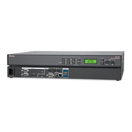
The DVS 605 AD is shown here. All other DVS 605 models have some but not all of the features shown below.
DVS 605 AD
1
3
UNIVERSAL
2
4
100-240 VAC ~ .7A MAX
50/60Hz
2
1
Power and video input connections
a
AC power connector
b
Universal analog VGA connectors
— inputs 1 and 2
c
HDMI connectors — inputs 3-5
(Note: PIP is not available on input 5.)
d
Audio 5-pole captive screw connectors
— inputs 1- 5 (audio models only)
Mounting and Cabling
Step 1 — Mounting
Turn off or disconnect all equipment power sources and rack mount the DVS 605 unit
using the pre-installed brackets (see image at right).
Step 2 — Connect inputs
Connect inputs from video sources to the applicable connectors marked "Inputs".
b
c
See
through
above for video connector types and
Step 3 — Connect outputs
Connect video and audio output devices to the applicable connectors marked "Outputs"
e
k
(see
through
above).
Step 4 — Connect control devices
LAN port
m
— Connect an LAN or WAN via this RJ-45 connector for remote control of the DVS 605 using an Internet browser or
the Extron configuration program, installed on a connected PC.
One connection LED lights green when connected to the LAN and one flickers amber as the devices communicate.
NOTE:
Do not use standard telephone cables for LAN connection, as they do not support Ethernet or Fast Ethernet.
Do not stretch or bend cables as transmission errors could occur.
RS-232/IR port — For serial RS-232 control, connect a host computer or control system to the 5-pole captive screw connector
RS-232 protocol (default values): 9600 baud, 1 stop bit, no parity, 8 data bits, no flow control. By default the IR port is disabled.
Contact closure port — For remote input selection of any of the five inputs, connect a suitable contact closure control device to
the 5-pole captive screw connector
) commands.
™
3
8
7
INPUT
OUTPUTS
5
AUX
3G/HD - SDI
GENLOCK
HDMI
RESET
HDMI
RGB/R-Y, Y, B-Y
5
6
12
e
HDMI connector
f
RGB/R-Y,Y, B-Y component VGA
connector
g
3G/HD-SDI connector (optional)
(SDI models only)
h
Genlock connectors — input and loop
through (SDI models only)
i
Audio output (fixed), 5-pole captive
screw connector (audio models only)
j
RCA audio (S/PDIF) output connector
(audio models only)
o
. The contact closure port and the RS-232 port share a common ground.
15
REMOTE
1 2 3 4 5
CONTACT
1
2
RS-232
IR
L
R
L
Tx Rx
G
G
S
LAN
13
14
Output, user interface, and control connections
d
for audio connectivity.
AUDIO INPUTS
AUDIO OUTPUTS
3
4
5
FIXED
FIXED
R
L
R
L
R
L
R
L
R
S/PDIF
4
9
10
k
Audio output (variable), 5-pole captive
screw connector (audio models only)
l
Reset button and LED
m
RJ-45 LAN connector
n
RS-232 and IR 5-pole captive screw
connector
o
Contact closure 5-pole captive screw
connector (shares a ground with RS-232)
Rack Mount
Bracket
VARIABLE
L
R
11
n
.
1
Advertisement
Table of Contents

Related Manuals for Extron electronics DVS 605


Summary of Contents for Extron electronics DVS 605
-
Page 1: Rear Panel Features
For full installation, configuration, menus, connector wiring, and operation details, see the DVS 605 User Guide, available at www.extron.com Installation Rear Panel Features The DVS 605 AD is shown here. All other DVS 605 models have some but not all of the features shown below. DVS 605 AD INPUT OUTPUTS REMOTE... -
Page 2: Front Panel Overview
Powering Up When powering up the DVS 605 unit, it undergoes a self testing sequence (see image below). The LCD displays the default display cycle, with the signal type, resolution, and refresh rate for the currently selected input and the output resolution and refresh rate. - Page 3 To configure the unit using the Extron Configurator software, the software must be installed (from the included DVD or from www.extron.com) on a PC connected to the DVS 605 via an RS-232 or a LAN connection, or via the front panel USB config port.
- Page 4 Basic SIS Commands Table The DVS 605 can be configured with specific SIS commands via RS-232 or a LAN connection. This table lists a selection of the commands. For a full list of SIS commands and variables see the DVS 605 User Guide, online at www.extron.com...
Need help?
Do you have a question about the DVS 605 and is the answer not in the manual?
Questions and answers