Extron electronics DVS 605 User Manual
Dvs 605 series
Hide thumbs
Also See for DVS 605:
- Setup manual (4 pages) ,
- Setup manual (4 pages) ,
- User manual (133 pages)

Related Manuals for Extron electronics DVS 605


Summary of Contents for Extron electronics DVS 605
- Page 1 User Guide Scalers and Signal Processors DVS 605 Series HDCP-Compliant Scalers (with Seamless Switching) 68-2110-01 Rev. D 09 16...
- Page 2 Safety Instructions Safety Instructions • English Istruzioni di sicurezza • Italiano WARNING: This symbol, , when used on the product, is intended to AVVERTENZA: Il simbolo, , se usato sul prodotto, serve ad alert the user of the presence of uninsulated dangerous voltage within avvertire l’utente della presenza di tensione non isolata pericolosa the product’s enclosure that may present a risk of electric shock.
- Page 3 より 『Extron Safety www.extron.com and Regulatory Compliance Guide』 (P/N 68-290-01) をご覧ください。 Copyright © 2016 Extron Electronics. All rights reserved. Trademarks All trademarks mentioned in this guide are the properties of their respective owners. The following registered trademarks®, registered service marks( ), and trademarks( ) are the property of RGB Systems, Inc.
- Page 4 FCC Class A Notice This equipment has been tested and found to comply with the limits for a Class A digital device, pursuant to part 15 of the FCC rules. The Class A limits provide reasonable protection against harmful interference when the equipment is operated in a commercial environment.
- Page 5 Conventions Used in this Guide Notifications The following notifications are used in this guide: Potential risk of severe injury or death. WARNING: AVERTISSEMENT : Risque potentiel de blessure grave ou de mort. CAUTION: Risk of minor personal injury. ATTENTION : Risque de blessure mineure. ATTENTION: •...
-
Page 7: Table Of Contents
Contents Other DVS 605 Operating Features ....31 Introduction ............1 Screen Save ..........31 DVS 605 Series Description ........ 1 Power Save ..........31 Licensed Third-Party Software Used in the Custom EDID/Custom Output Resolution ..31 DVS 605 ............2 The OSD Bug .......... - Page 8 Reset Device Page ........122 Mounting ............. 123 Tabletop Placement ........123 Rack Mounting ..........123 UL Guidelines for Rack Mounted Devices ............ 123 Rack Mounting the DVS 605 ...... 124 Furniture Mounting ......... 124 Extron Warranty ..........125 DVS 605 • Contents viii...
-
Page 9: Introduction
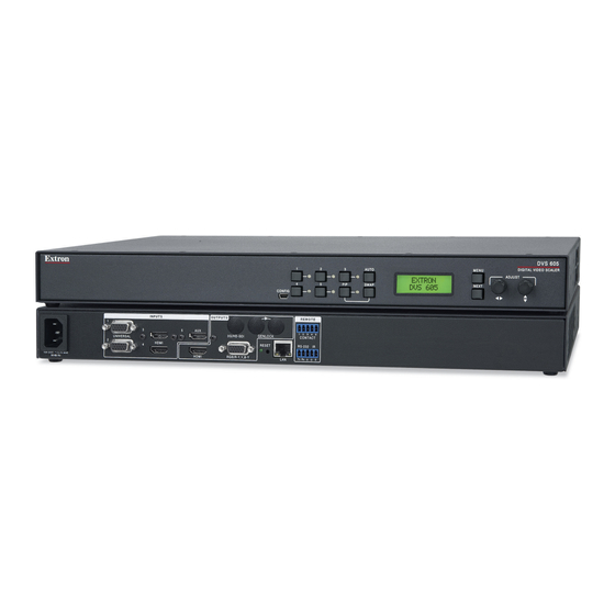
DVS 605 AD, with 3G/HD-SDI output and audio switching All models are full rack width, and are available with optional 3G/HD-SDI outputs (DVS 605 D and DVS 605 AD) and balanced or unbalanced audio (DVS 605 A and DVS 605 AD). -
Page 10: Licensed Third-Party Software Used In The Dvs 605
DVS 605 models with audio switching feature HDMI audio embedding and de-embedding. Any input audio signal can be embedded onto the HDMI output. DVS 605 audio models can also extract embedded HDMI audio to analog and digital S/PDIF outputs. The DVS 605 AD, with audio switching plus 3G-SDI/HD-SDI output, can embed up to eight channels of audio onto the SDI output. -
Page 11: Key Features
The unit can be set up to automatically switch to an active input, by giving priority to the highest active input (5 to 1), or to the lowest active input (1 to 5). This allows for simple, automated control of the DVS 605 when a control system is not in use. -
Page 12: Audio
Audio Audio switching — The DVS 605 A and DVS 605 AD feature audio switching for five • analog stereo balanced or unbalanced inputs. • Output volume control — DVS 605 audio models provide master volume control for analog audio only. Fixed and variable line level outputs are available, and each output can be balanced or unbalanced. - Page 13 The label can be up to 16 characters and input via RS-232 or Ethernet. • Power screen saver mode and standby modes — The DVS 605 can be set to automatically mute video and sync output to the display device when no active input signal is detected.
-
Page 14: Controlling The Dvs 605
Internal universal power supply — The 100-240 VAC, 50-60 Hz, international power supply provides worldwide power compatibility. Controlling the DVS 605 All DVS 605 Series units can be controlled using one or more of the following methods: The front panel controls. •... -
Page 15: Rear Panel Connections
This section describes how to connect cables to a DVS 605 scaler. Rear Panel Cabling The illustration below shows all the possible rear panel features of the audio (DVS 605 A and DVS 605 AD) and the non-audio (DVS 605 and DVS 605 D) models. - Page 16 Loosely place the included tie wrap around the HDMI connector and LockIt lacing bracket. While holding the connector securely against the lacing bracket, tighten the tie wrap, then remove any excess length. DVS 605 • Rear Panel Connections...
- Page 17 1080i, 1080p, or 2K at 23.98, 24, or 25 Hz. Genlock connectors (and loop through, SDI models only) — Connect an external reference signal for synchronization of the SDI output. The loop through can be used to synchronize additional devices. DVS 605 • Rear Panel Connections...
- Page 18 RJ-45 Connector Figure 6. RJ-45 LAN Connector Wiring LAN Activity LED — A blinking yellow LED indicates LAN activity. Activity Link Link LED — The green LED lights to indicate a good LAN connection. DVS 605 • Rear Panel Connections...
- Page 19 — For remote input selection of any of the five inputs, connect a suitable contact closure control device to this 5-pole captive screw connector. The contact closure port and the RS-232 port share a common ground. DVS 605 • Rear Panel Connections...
-
Page 20: Operation
Operation This section of the manual discusses the operation of a DVS 605 device. Topics covered include: • Front Panel Overview Powering Up • • DVS 605 Menu System — Configuration and Adjustments • Front Panel Lockout (Executive Modes) •... -
Page 21: Powering Up
Powering Up When applying power to the DVS 605, the unit undergoes a start-up self-testing sequence (see image below) and then the LCD displays the default display cycle. Default Display Cycle When in use but not in any menu mode, the LCD screen defaults to cycling through the input and output configuration currently installed. - Page 22 NOTE: If no signal is present on the currently selected input, appears in NO SIGNAL place of the input type. For example, INPUT 4 NO SIGNAL Details of each of the menus are on subsequent pages after the main flow chart. DVS 605 • Operation...
- Page 23 DVS 605 • Operation...
-
Page 24: User Presets
To return to the default cycle from within any menu, press the button repeatedly until Menu menu appears, then press the button. Alternatively, allow the DVS 605 to Exit Next time-out (after 20 seconds). Submenus are accessed from a main menu by pressing the button. -
Page 25: Input Configuration
They can also be set to autodetect the incoming input signal type. This is the default setting. Inputs 3 through 5 Inputs 3 through 5 are digital inputs for HDMI or DVI input signals. DVS 605 • Operation... -
Page 26: Output Configuration
1280 x 1024 1360 x 765 1360 x 768 1365 x 768 1366 x 768 1365 x 1024 1440 x 900 1400 x1050 1600 x 900 1680 x 1050 1600 x 1200 1920x1200 480p 576p 720p 1080i 1080p DVS 605 • Operation... - Page 27 The HDCP Notification provides a means of determining if HDCP content restrictions are preventing a video signal from passing. The DVS 605 has the ability to notify the user that they are currently trying to view HDCP protected content through a non-HDCP compliant output port (15-pin HD or 3G/HD-SDI) or a non-HDCP compliant HDMI or DVI display.
- Page 28 DVS 605 HDMI input supports HDCP authorization. If the user were going to use only the HDMI output of the DVS 605 to a display (sink) that supported HDCP, there would be no issue. However, if the user wanted to use the DVS 605 analog 15-pin HD output to an analog sink, the green HDCP notification screen would be displayed, due to the source unnecessarily enabling encryption on its HDMI output.
- Page 29 Accu-RATE frame lock (AFL) on page 79). When using the SDI genlock, the output rate of the DVS 605 must be set to match the applied SDI genlock reference signal, for example 1080i at 59.94 Hz. NOTE: When the DVS 605 is set for input signal lock, a glitch in output sync may be experienced when switching between inputs as the scaler locks to the input reference.
-
Page 30: Audio Configuration (All Models)
256 byte EDID (HDMI) is presented to the source allowing for all digital audio formats. NOTE: DVS 605 analog audio outputs are active only if analog or PCM audio is detected on HDMI inputs 3, 4, and 5. 2-channel auto 256 byte EDID (HDMI) is presented to the source requesting 2CH PCM audio. -
Page 31: Advanced Configuration
Occasionally additional audio delay is required to account for other signal processors, scalers, or display devices in a system. For these situations, the DVS 605 offers an additional 0-255 millisecond static global audio delay which can be Audio delay... - Page 32 16:10). This setting has the correct letter box or pillar box settings visible under the Image Size and Image Position Picture Controls. When the DVS 605 is in the Fill mode, if an aspect ratio adjustment for a single input rate is desired, the correct size and center can be set up using...
- Page 33 The default state is Off. OSD duration The DVS 605 displays a small OSD bug in the upper left corner of screen when switching between inputs. It contains information regarding the detected input rate and format, the HDCP status of the selected input, and an indication of Main vs. PIP inputs. The duration the OSD bug is on-screen can be set from 1 to 500 seconds via the front panel menu.
-
Page 34: View Comm Settings
Edit Comm Settings Menu Exit Menu From this submenu, press the button to return to the menu cycle, or Menu User Presets press the button to exit the menu and return to the default cycle. Next DVS 605 • Operation... -
Page 35: Front Panel Lockout (Executive Modes)
Executive mode 1 locks all front panel functions completely. This mode can be enabled or disabled by SIS commands (see Front panel security lockout (Executive Mode) front panel lockout mode page 52), PCS (see on page 91), or internal web pages (see Executive Mode on page 119). DVS 605 • Operation... -
Page 36: Window Vs. Image Size And Position - An Overview
Window vs. Image Size and Position — An Overview The DVS 605 provides users the ability to adjust a window size and position and the image (the content) size and position independently with regards to the output raster. This independent control is available for both the Main and PIP windows, allowing the user comprehensive flexibility in output configurations. -
Page 37: Picture-In-Picture (Pip) Mode
A clean cut through black is used during Main or PIP input switches. Some PIP or Main input switch combinations require the DVS 605 output to briefly cut to black to allow the new inputs to be set up. This is normal operation of the scaler. -
Page 38: Pip Presets
PIP windows and content settings. Sixteen global PIP presets are available for the DVS 605. A set of 10 factory default layouts exist and can be overwritten by saving new presets. -
Page 39: Other Dvs 605 Operating Features
Screen Saver Settings section on page 114). Power Save The Power Save mode allows the user the ability to put the DVS 605 into a low power state. Use the SIS commands (see Power Save Mode on page 48), or the internal Web... -
Page 40: The Osd Bug
HDCP Lock Hardwired IR Port The DVS 605 includes a hardwired IR input, to be used with a hardwired IR output from an Extron MLC, IPL, or similar controller. This port allows for simple, unidirectional control of the DVS 605 from a host controller that has no available RS-232 ports, but does have available hardwired IR outputs. -
Page 41: Resetting The Unit
NOTE: The reset modes listed close all open IP and Telnet connections and sockets. Each mode is a separate function, and not a continuation from mode 1 to mode 5. DVS 605 Reset Mode Summary Mode Activation... -
Page 42: Sis Communication And Control
SIS Communication and Control The DVS 605 can be configured and controlled via a host computer or other device (such as a control system) attached to the rear panel RS-232 connector or the LAN port or the front panel USB port. Control is made using the Extron Simple Instruction Set (SIS) of commands, or the DVS Web pages. -
Page 43: Password Information
Error Responses When the DVS 605 receives a valid command, it executes the command and sends a response to the host device. If the unit is unable to execute the command because the command contains invalid parameters, it returns an error response to the host. -
Page 44: Symbol Definitions
Text label/preset name: up to 16 characters NOTE: User and input presets saved without a name are saved with the default names “User Preset xx” (for example, user preset 12) or “Input preset xxx” (for example, Input preset 122). DVS 605 • SIS Communication and Control... - Page 45 1024x768 1024x852 1024x1024 1280x768 1280x800 1280x1024 1360x765 1360x768 1365x768 1366x768 1365x1024 1440x900 1400x1050 1600x900 1680x1050 1600x1200 1920x1200 480p 576p 720p 1080i 1080p 2048x1080 2K Default output resolution Figure 27. SIS Command EDID Table DVS 605 • SIS Communication and Control...
- Page 46 HDCP status (valid only on HDMI/DVI outputs): 0 = No sink or source detected 1 = Sink or source detected with HDCP 2 = Sink or source detected but no HDCP is present DVS 605 • SIS Communication and Control...
- Page 47 Static audio delay, 0 through 255 milliseconds (default is 0) NOTE: The static audio delay is in addition to the automatic audio delay that is applied by the DVS 605 to compensate for internal video processing. Video signal status 0 = Video / TMDS signal not detected 1 = Video / TMDS signal detected DVS 605 •...
- Page 48 DHCP is disabled by default. Default IP is 192.168.254.254. X10( Hardware (MAC) address (00-05-A6-xx-xx-xx). X11) Subnet mask (xxx.xxx.xxx.xxx). Leading zeros are optional in setting values in each of four fields, and are suppressed in returned values. Default subnet mask = 255.255.0.0 DVS 605 • SIS Communication and Control...
- Page 49 Mode 1 reset was executed and the default factory firmware version is loaded. An exclamation point (!) indicates corrupted firmware. [Example: 1.03*(1.42-DVS 605 -Thur, 21 Apr 2012 22:30:57 GMT).] The SIS Command and Response tables start on the next page.
-
Page 50: Sis Command And Response Table
6 = DVI/HDMI (only available for inputs 3, 4, and 5), 7 = Auto detect (default for inputs 1 and 2) X1$ = Text label or preset name, up to 16 characters X2& = PIP window input selection: 0 to 4 (0 = off) DVS 605 • SIS Communication and Control... - Page 51 6 = Custom EDID/output rate 4, 7 = Custom EDID/output rate 5. For variables 10-92, see the SIS EDID table on page 37. X3@ = Auto-Image threshold value: 0 (black) though 100 (white), default = 25 DVS 605 • SIS Communication and Control...
- Page 52 X% = Pixel phase: 0 to 63 (default = 31) X^ = Total pixels: ±512 of the default value X& = Active pixels: ±512 of the default value X* = Active lines: ±512 of the default value DVS 605 • SIS Communication and Control...
- Page 53 X( = Enable/disable: 0 = off/disable, 1 = Auto/enable X1% = Picture adjustment: 0 to 127 (default = 64) X3! = Video mute: 0 = off/disable, 1 = on/enable (mute to black), 2 = mute output sync and video DVS 605 • SIS Communication and Control...
- Page 54 X1^ = Horizontal and vertical position: ±11000, with leading “+” or “-”, for example -02040 X1& = Horizontal and vertical size: 10 to 11000 X1* = Image/window number: 1 = main window, 2 = PIP window DVS 605 • SIS Communication and Control...
- Page 55 0 = Auto (based on sink EDID), default; 1 = DVI, 2 = HDMI 444 RGB, 3 = HDMI 444 YUV “FULL”, 4 = HDMI 444 YUV “LIMITED”, 5 = HDMI 422 YUV “FULL”, 6 = HDMI 422 YUV “LIMITED”. DVS 605 • SIS Communication and Control...
- Page 56 X4^ = Screen saver status: 0 = Active input detected, timer not running, 1 = No active input, timer is running, output sync still active, 2 = No active input, timer has expired, output sync disabled DVS 605 • SIS Communication and Control...
- Page 57 X4@ = Audio input type: 0 = none, 1 = analog, 2 = 2Ch digital, 3 = Full digital, 4 = 2Ch digital auto, 5 = Full digital auto (see on page 39). DVS 605 • SIS Communication and Control...
- Page 58 PIP Input Number Figure 28. Preset Options NOTE: X1$ = Text label: up to 16 characters X2# = User presets or PIP presets: 1 to 16 X2$ = Input presets: 1 to 128 DVS 605 • SIS Communication and Control...
- Page 59 X3& = Auto switch mode: 0 = disable (default), 1 = priority to highest numbered input, 2 = priority to lowest numbered input X5@ = Freeze status: 1= all frozen, 2 = Main frozen, 3 = PIP frozen, 0 = all unfrozen (default) DVS 605 • SIS Communication and Control...
- Page 60 2 = sink or source detected but no HDCP is present X3% = Effect duration: from 2 to 50, in 0.1 second steps (where 2 = 0.2 seconds, 50 = 5.0 seconds), default = 3 (0.3 seconds) DVS 605 • SIS Communication and Control...
- Page 61 NOTES: Genlock offset commands return an error unless: a) a DVS 605 D or AD is present, b) SDI genlock is currently enabled, and, c) Genlock is currently locked to an applied genlock reference. Genlock offsets apply only to current output resolution, and reset to 0,0 when the output resolution is adjusted.
- Page 62 1 to 500 in 1 second increments, 501 = OSD never times out or output sync never times out X4$ = Video signal status: 0 = video or TMDS signal not detected, 1 = video or TMDS signal detected DVS 605 • SIS Communication and Control...
- Page 63 X3! = Video mute: 0 = off or disable, 1 = on or enable (mute to black) X10) = Default name: combination of model name and last three pairs of MAC address (for example DVS-605-Series-07-8C-EC) DVS 605 • SIS Communication and Control...
-
Page 64: Sis Command And Response Table For Ip Control Port
DVS 605 • SIS Communication and Control... - Page 65 DVS 605 • SIS Communication and Control...
- Page 66 DVS 605 • SIS Communication and Control...
- Page 67 DVS 605 • SIS Communication and Control...
- Page 68 DVS 605 • SIS Communication and Control...
-
Page 69: Product Configuration Software
The Extron Product Configuration Software (PCS version 3 or later) offers another way to configure the DVS 605 via USB or TCP/IP connection in addition to the SIS commands. This section describes the software installation and communication. For in operation configuration information see the DVS 605 Product Configuration Software help file. -
Page 70: Starting The Software
To connect to a device, select the desired device and click the button ( ). A Connect new device configuration tab opens. Alternatively, double click the desired device name to connect and open to the configuration page. DVS 605 • Product Configuration Software (PCS) -
Page 71: Tcp/Ip Panel
Show Characters visible when entering them. In the field ( ), enter the Telnet port of the desired device. Telnet Port Click the button ( ). A new device tab opens. Connect DVS 605 • Product Configuration Software (PCS) -
Page 72: Offline Device Preview
Offline Device Preview It is possible for the DVS 605 pages to be viewed without connecting directly to a device, but the page settings cannot be changed or saved. To open as an offline device, click the drop-down menu and select Configuration File Figure 34. -
Page 73: Using The Software
Using the Software NOTE: For detailed software navigation, open the DVS 605 Product Configuration Software Help file. When connected to an online device, a connection status icon (circle) shows green on the device name tab (see figure 36, The configuration page has a global navigation bar (ribbon) (... -
Page 74: Device Menu
From the drop-down menu, select . The Device Settings > Hardware Settings... dialog box opens (see the DVS 605 PCS Help file, for configuration Hardware Settings details). Figure 38. Hardware Settings Dialog Box DVS 605 • Product Configuration Software (PCS) - Page 75 Alternatively, to manually assign an IP address, complete all the fields as desired. Click the button ( ) to accept pending changes and close the dialog box. Apply Clicking the button ( ) cancels any pending changes and closes the dialog box. Cancel DVS 605 • Product Configuration Software (PCS)
- Page 76 This option allows the user to backup all audio, video, and communication settings from a DVS 605 device to a PC. This saved configuration can later be restored to a single connected device, or used to replicate the settings from one DVS 605 to other DVS 605 devices, if the device models are the same.
- Page 77 The saved configuration can be restored to a single device or to multiple devices, if the models are the same as that used for the backup. To restore a configuration to a single device: Connect to the DVS 605 device via LAN to a PC where the backup configuration file resides. Select...
- Page 78 The window closes after restoring, and a confirmation pop-up is shown briefly to indicate the process is complete. To restore a configuration to multiple devices: Connect to the DVS 605 device via LAN. Ensure the receiving devices are also connected via LAN to the same network. Select...
- Page 79 Update Firmware Update progress of the firmware upload to the device. To update firmware to multiple devices: Connect the host PC to all the target DVS 605 devices on the same network via LAN. Select and then Update Firmware Update Firmware To Multiple Devices...
- Page 80 As default, all targets are preselected for deployment and have a check mark to the left of the device details list. NOTE: PCS verifies the correct DVS 605 model, IP address, telnet port, and device administrator password for each device in the list upon updating the firmware. PCS does not update firmware on a device if one of the above criteria is not valid and this is reflected in the Status column.
- Page 81 About This Module Figure 48. About This Module Dialog Box Click the button to close the dialog box. Close NOTE: Your version number may be different from that shown above. DVS 605 • Product Configuration Software (PCS)
-
Page 82: Av Controls Panel
) to allow the audio to follow the PIP Audio Follows PIP output. • Select the button ( ) to swap the output from the Main Input source to the PIP Swap input. DVS 605 • Product Configuration Software (PCS) - Page 83 ) to mute video and sync. The button turns red along Sync Mute with the button Video Mute To unmute any signal, click the appropriate button. The button reverts to the default color, indicating the signal has been unmuted. DVS 605 • Product Configuration Software (PCS)
-
Page 84: Configuration Pages
— Scales the input signal to fill the entire video output. Fill • — Follows the signal aspect ratio, with respect to the current output Follow resolution setting. Black letter box or pillar box bars may be applied for aspect ratio compensation. DVS 605 • Product Configuration Software (PCS) - Page 85 Film Detect Select the check box ( ) of the desired input to enable automatic 3:2, 2:2, Film Detect and 24:1 film pulldown detection for NTSC, PAL, SECAM, and 1080i input signals. DVS 605 • Product Configuration Software (PCS)
- Page 86 — Image dissolves over a selectable time frame (0.2 to 5 seconds) before Dissolve switching to the newly selected video. Set the time as desired. — Switches video directly to the newly selected input. • DVS 605 • Product Configuration Software (PCS)
- Page 87 White Field White Field Blue Mode 1.33 Aspect 1.78 Aspect 1.85 Aspect 2.35 Aspect Figure 53. Available Test Patterns NOTE: No input signal is needed when using a test pattern for display device setup. DVS 605 • Product Configuration Software (PCS)
-
Page 88: Edid Minder Page
( ) on the Favorites Available EDID Connected Outputs left, select the desired EDID. From the inputs group box, click the button ( ) to assign EDID to the Assign selected inputs. DVS 605 • Product Configuration Software (PCS) - Page 89 Save to EDID Library Click the button to save the file. NOTE: Saving a factory EDID exports an HDMI, LPCM- 2Ch EDID to the PC. The file is saved as a .bin file. DVS 605 • Product Configuration Software (PCS)
-
Page 90: Image Settings Page
(see Down figure 56, ). An asterisk beside a chosen value for a signal sampling setting indicates that it is a default value for the applied video signal. DVS 605 • Product Configuration Software (PCS) - Page 91 Auto Phase routine (YUV and RGB only) and centers and sizes the input according to table values. Figure 58. Overscan Section For each input signal type, select a value from the corresponding drop-down menu. NOTE: Setting a value of disables overscan for the corresponding input format. DVS 605 • Product Configuration Software (PCS)
- Page 92 NOTE: User presets can be saved on one input resolution and recalled on a different one. Input presets can only be recalled on the same input resolution that was present when the preset was saved. DVS 605 • Product Configuration Software (PCS)
- Page 93 User Presets Click the button ( ). The dialog box opens. Recall Preset Presets Click the button to recall the preset. Click the button to return to the Recall Cancel page. Image Settings DVS 605 • Product Configuration Software (PCS)
-
Page 94: Size And Position Page
To adjust the size and position numerically: Enter a value or click the arrow in the Down Horizontal Size fields ( Vertical Size Enter a value or click the arrow in the Down Horizontal Position fields ( Vertical Position DVS 605 • Product Configuration Software (PCS) - Page 95 ) and select the setting. Restore to Defaults Each preset can be recalled with or without inputs (default recall). To recall with inputs click the drop-down menu ( ) and choose Recall Recall with Inputs DVS 605 • Product Configuration Software (PCS)
-
Page 96: Audio Configuration Page
), then set the input gain to optimal settings. • For inputs 1 and 2, only the options are available. None Analog For inputs 3-5, six options are available (see the list at right). • DVS 605 • Product Configuration Software (PCS) - Page 97 1 ms increments. • Click in the level text field below the fader ( ) and enter a new value. Then, press the £ <Enter> or <Tab> key to apply the change. DVS 605 • Product Configuration Software (PCS)
-
Page 98: General Settings Page
HDCP status of the selected input source. Use this setting when DVI sink devices initially pass HDCP encrypted content, but intermittently display a green HDCP notification screen after a power cycle or resuming from sleep mode. DVS 605 • Product Configuration Software (PCS) -
Page 99: Software Menu
Show Expanded Device Tabs Figure 66. Expanded Device Tab Software Settings This option resets all disabled confirmation dialogs to the default settings. From the menu, select ). The Software Software Settings Software dialog box opens. Settings DVS 605 • Product Configuration Software (PCS) - Page 100 From the menu, select (see ). The Software Extron PCS Help Product file opens in a new window. Configuration Software DVS 605 Help Figure 69. Production Configuration Software Help File Window DVS 605 • Product Configuration Software (PCS)
- Page 101 (see figure 71, ) to Close Session(s) and Exit disconnect the software from connected devices, close all offline device tabs, and close the software. Click the button ( ) to leave the software open. Cancel DVS 605 • Product Configuration Software (PCS)
-
Page 102: Using The Default Web
The DVS 605 features an internal Web server, displayed as a set of default Web pages. These pages allow you to configure and operate the DVS 605 unit via a LAN or WAN connection through the RJ-45 port, using a Web browser such as the Microsoft Internet ®... -
Page 103: Turning Off Compatibility Mode
Be sure that the check box is Display all websites in Compatibility View cleared, and that the IP address of the DVS 605 is not in the list of Web sites that have been added to Compatibility view. Navigating the Default Web Pages... -
Page 104: Configuration Pages
AV Controls Panel At the bottom of the panel is a summary of the current active input and output status, which includes signal format, resolution and refresh rate, HDCP status, and Genlock/AFL status ( DVS 605 • Using the Default Web Pages... - Page 105 Freeze button Click ) to freeze the current video image. The button is blue when image is Freeze frozen. Click it again to unfreeze the image. The buttons reverts to the default color. DVS 605 • Using the Default Web Pages...
-
Page 106: Input/Output Configuration Page
• RGB Scaled • — With this setting selected, the device detects if YUVi or YUVp/HDTV is Auto YUV applied and sets the input accordingly. • RGBcvS • S-Video • Composite DVS 605 • Using the Default Web Pages... - Page 107 (see the table in the Auto Memory section on page 24 for the Auto Memory and Auto-Image relationship). When Auto Memory is disabled, the DVS 605 treats every newly applied input as a new source. HDCP Authorized...
- Page 108 Click the arrow and from the drop-down menu box ( ) select the applicable sync polarity, Choices are: H-/ V- (default), H+/ V-, H+/ V+, H-/ V+. NOTE: The sync polarity option is only available when the output format is RGBHV. DVS 605 • Using the Default Web Pages...
- Page 109 (see Genlock/AFL Mode on page 20 for details). Select as desired ( NOTE: The SDI genlock option is available only on DVS 605 D and DVS 605 AD models. Test pattern To aid display device setup and optimization, select a test pattern (...
-
Page 110: Edid Minder Page
From this page an EDID data set can be assigned to any input with an Auto-Detect, an RGB, or an HDMI/DVI input type. The currently assigned EDID properties can be viewed and EDID files can be loaded to and from the DVS 605. Figure 77. - Page 111 ( upper right of screen), click Output Resolution Match Output EDID can be filtered or saved (see EDID Minder Page in the PCS chapter on pages 80 and 81 for details). DVS 605 • Using the Default Web Pages...
-
Page 112: Image Settings Page
Auto-Image 99 for steps to set automatic activation). Select : with fill (to fill the entire video output) or : with follow Auto-Image Auto-Image (to maintain the aspect ratio of the input). DVS 605 • Using the Default Web Pages... - Page 113 * PIP presets can be recalled with or without the main and PIP inputs that were active when the preset was saved. NOTE: “H/V Start” indicates the horizontal and vertical start. Figure 80. Presets Settings DVS 605 • Using the Default Web Pages...
- Page 114 Input Presets A total of 128 global input presets are available for the DVS 605. An input preset is a user-defined set of input and picture control settings that can be saved for each source within a system so that they can be recalled whenever the source is applied. Input presets are unique to the signal that was applied when the preset was initially saved.
-
Page 115: Pip Settings Page
PIP Settings Page In PIP mode, the DVS 605 can display two images on the screen simultaneously. From this page, the PIP settings can be adjusted. This includes input selection, swapping between the main and PIP inputs, adjustment of the picture control settings, main and PIP window position and sizing, and the saving and recalling of PIP presets. - Page 116 NOTE: In steps 2 or 3, if a value above or below the accepted range is entered, a red border is displayed and a pop-up window indicates the accepted minimum or maximum value. DVS 605 • Using the Default Web Pages...
- Page 117 PIP presets Sixteen global PIP presets are available for the DVS 605 (see figure on page 107). A PIP preset contains settings for the size and position of PIP. It also contains the main and PIP inputs that were active when the preset was saved. By default, the first ten PIP presets have settings already associated with them, but they can be overwritten (see figure 82).
-
Page 118: Audio Settings Page
(for analog inputs). Also analog audio output format can be set and adjusted. NOTE: • Audio inputs 1 and 2 are disabled for DVS 605 and DVS 605 D models. They do not support analog audio. • Input gain cannot be adjusted for digital audio. - Page 119 ( ). Audio delay can be set from 0 ms to 255 ms. Audio Delay NOTE: The DVS 605 automatically delays audio signals to compensate for internal video processing. Click and drag the handle of the fader, or click the...
-
Page 120: Preset Management Page
Recall PIP Preset Select one of the following: • Recall: Inputs, Size & Position • Recall: Size & Position Only In the dialog box, click DVS 605 • Using the Default Web Pages... -
Page 121: Device Settings Page
( ), video and sync mute ( ), OSD input range ( ), and HDCP mode( Click this button to open the s page. Device Setting Figure 85. Device Settings Page DVS 605 • Using the Default Web Pages... - Page 122 HDCP compliant and an HDCP encrypted input has been selected. To select the display color, select the radio button or radio button. Black Green DVS 605 • Using the Default Web Pages...
- Page 123 HDCP status of the selected input source. Use this setting when DVI sink devices initially pass HDCP encrypted content, but intermittently display a green HDCP notification screen after a power cycle or resuming from sleep mode. DVS 605 • Using the Default Web Pages...
-
Page 124: Hardware Pages
License dialog box (shown at right) opens (see Information Licensed Third-party Software Used in the DVS 605 on page 2 for a list of the software used). To view a copy of a listed package license, click the link in the License column for the relevant package. -
Page 125: Device Name Page
This page allows the user to adjust device settings for RS-232 (see figure 89, ) and Ethernet ( ) connections. Click this button to open the page. Figure 89. Connection Settings Page DVS 605 • Using the Default Web Pages... -
Page 126: Firmware Loader Page
Default Gateway Click Save Firmware Loader Page This page allows the user to update the device firmware. Click this button to open the page. Figure 90. Firmware Loader Page DVS 605 • Using the Default Web Pages... -
Page 127: Executive/Power Mode Page
Mode 1: Lock Front Panel • Mode 2: Limit Front Panel to Input Selection, PIP, and Auto-Image To set executive mode: Click the radio button for the desired lockout option. Click Apply DVS 605 • Using the Default Web Pages... -
Page 128: Date And Time Page
PC or manually adjust the date and time using the drop-down calendar and the fields ( ). Click ) when done. Date Time Save DVS 605 • Using the Default Web Pages... -
Page 129: Password Page
( User Password In the field, re-enter the user password. Confirm Password Click Save NOTE: When passwords are set, a notification to close and restart the browser appears. DVS 605 • Using the Default Web Pages... -
Page 130: Reset Device Page
Click the desired radio button of the three reset options ( Click ). A confirmation dialog Reset box opens. In the dialog box, click to continue with the reset, or to abort the reset. DVS 605 • Using the Default Web Pages... -
Page 131: Mounting
Furniture Mounting If the DVS 605 is to be rack mounted, it is important to mount it before cabling it. Four rubber feet are included with the unit. Install the feet only if the unit is to be mounted on a tabletop (see Tabletop Placement below). -
Page 132: Rack Mounting The Dvs 605
Rack Mounting the DVS 605 To rack mount the DVS 605, turn off or disconnect all equipment power sources and rack mount the DVS 605 unit using the pre-installed brackets (see figure 95). Rack Mount Bracket Figure 95. Rack Mounting the DVS 605... -
Page 133: Extron Warranty
Extron Electronics makes no further warranties either expressed or implied with respect to the product and its quality, performance, merchantability, or fitness for any particular use. In no event will Extron Electronics be liable for direct, indirect, or consequential damages resulting from any defect in this product even if Extron Electronics has been advised of such damage.
Need help?
Do you have a question about the DVS 605 and is the answer not in the manual?
Questions and answers