Table of Contents
Advertisement
Quick Links
English
Operating and Assembly Instructions
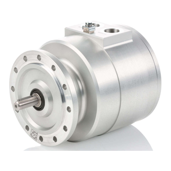
Incremental Encoder Ex FG 40
with Ex approval
Read the Operating and Assembly Instructions prior to
assembly, starting installation and handling!
Keep for future reference!
Translation of the original Operating and Assembly Instructions ExFG40_Manual_En_R7(2020-11-02)ID77099.docx
ID 77099
Advertisement
Table of Contents

Related Manuals for Hubner Ex FG 40


Summary of Contents for Hubner Ex FG 40
- Page 1 English Operating and Assembly Instructions Incremental Encoder Ex FG 40 with Ex approval Read the Operating and Assembly Instructions prior to assembly, starting installation and handling! Keep for future reference! Translation of the original Operating and Assembly Instructions ExFG40_Manual_En_R7(2020-11-02)ID77099.docx ID 77099...
- Page 2 Incremental Encoder Ex FG 40 Manufacturer / Publisher Johannes Hübner Phone: +49 641 7969 0 Fabrik elektrischer Maschinen GmbH Fax: +49 641 73645 Siemensstr. 7 Internet: www.huebner-giessen.com 35394 Giessen / Germany E-Mail: info@huebner-giessen.com Further current information on this product series can be found online in our Service Point.
- Page 3 Johannes Hubner Fabrik elektrischer Maschinen GmbH. Subject to errors and changes due to technical improvements. Copyright © Johannes Hubner Fabrik elektrischer Maschinen GmbH All rights reserved. ExFG40_Manual_En_R7(2020-11-02)ID77099.docx...
-
Page 4: Table Of Contents
Incremental Encoder Ex FG 40 Directory General .......................... 6 Information about the Operating and Assembly Instructions ........... 6 Scope of delivery ........................6 Explanation of symbols ......................7 Disclaimer..........................8 Copyright ..........................8 Guarantee terms ........................8 Customer service ........................8 Safety .......................... - Page 5 Incremental Encoder Ex FG 40 Dismantling the encoder ......................25 Faults ...........................26 Faults table ..........................26 Inspections ........................27 Safety instructions personnel ....................27 Maintenance information ......................27 Inspection schedule ....................... 27 Disposal ........................27 10 Repair ...........................28 11 Replacement parts ......................28 12 EU-Declaration of Conformity ..................29...
-
Page 6: General
The first installation work MUST ONLY be carried out by personnel who are able to provide verification of special training to work on Ex certified machinery. 1.2 Scope of delivery Incremental Encoder Ex FG 40, Operating and Assembly Instructions. ExFG40_Manual_En_R7(2020-11-02)ID77099.docx... -
Page 7: Explanation Of Symbols
Incremental Encoder Ex FG 40 1.3 Explanation of symbols Warnings are indicated by symbols in these Operating and Assembly Instructions. The warnings are introduced by signal words that express the scope of the hazard. The warnings must be strictly heeded; you must act prudently to prevent accidents, personal injury, and property damage. -
Page 8: Disclaimer
Incremental Encoder Ex FG 40 1.4 Disclaimer All information and instructions in these Operating and Assembly Instructions have been provided under due consideration of applicable guidelines, as well as our many years of experience. The manufacturer assumes no liability for damages due to: ... -
Page 9: Intended Use
Ambient temperature category protection -40°C … 55°C IP66 6000 rpm -40°C … 60°C IP66 6000 rpm -40°C … 55°C T85°C IP66 6000 rpm The incremental encoder Ex FG 40 can be used in saline environments e.g. on offshore drilling rigs. ExFG40_Manual_En_R7(2020-11-02)ID77099.docx... -
Page 10: Improper Use
Incremental Encoder Ex FG 40 It is not permissible to make any alteration to equipment that is used in potentially explosive environments. Repairs may only be carried out by authorized authorities provided by the manufacturer. Contravention invalidates the EX approval. -
Page 11: Special Dangers
Incremental Encoder Ex FG 40 2.6 Special dangers Residual risks that have been determined based on a risk analysis are cited below. 2.6.1 Electrical current DANGER! Life-threatening danger due to electrical shock! There is an imminent life-threatening hazard if live parts are touched. Damage to insulation or to specific components can pose a life-threatening hazard. -
Page 12: Technical Data
Incremental Encoder Ex FG 40 3 Technical Data 3.1 Type plates Below are some nameplates for different device models and signs shown. The type plate is located on the side of the housing and contains the following information: Manufacturer, address ... -
Page 13: Electrical And Mechanical Data
Incremental Encoder Ex FG 40 3.2 Electrical and mechanical data Pulse rates (square wave signals) Value Standard pulse rates 500, 600, 1000, 1024, 1200, 1300, 2500 Interpolation factors: 1, 2, 4, 8, 10, 20, 25 Resolution enhancement by signal (Example. : Basic-pulse rate... - Page 14 Incremental Encoder Ex FG 40 Output signals Sinus / Cosinus Value Pulse rates 500, 600, 1000, 1024, 1200, 1300, 2500 Connection data 12…30 VDC, ripple max. 10% Supply voltage No load-current consumption approx. 50 mA at 24 V Maximum current consumption approx.
- Page 15 Incremental Encoder Ex FG 40 Encoder temperature range See table page 9 12…30 VDC Supply voltage Protection class Sealing Permissible Rotor Breakaway torque acc. to speed moment of mechanically inertia DIN EN 60529 IP66 With radial shaft seal acc. table approx.
-
Page 16: Type Key
Incremental Encoder Ex FG 40 3.3 Type key 3.3.1 For pulse rates (square wave pulses) Ex FG 1024 Incremental encoder with Ex certification Series Connections, axial design AK: One system with terminal strip AKK: Two systems with terminal strip System 1:... -
Page 17: For Output Signals Sinus / Cosinus
Incremental Encoder Ex FG 40 3.3.2 For output signals Sinus / Cosinus Ex FG 1024 Incremental encoder with Ex certification Series Connections, axial design AK: One system with terminal strip AKK: Two systems with terminal strip System 1: Number of pulses... -
Page 18: For Output Signals Sinus / Cosinus - Pulse Rates (Square Wave Pulses)
Incremental Encoder Ex FG 40 For output signals Sinus / Cosinus – pulse rates (square wave pulses) 3.3.3 Ex FG 1024 Incremental encoder with Ex certification Series Connections, axial design AKK: Two systems with terminal strip System 1: Number of pulses... -
Page 19: Transport, Packaging And Storage
Incremental Encoder Ex FG 40 4 Transport, packaging and storage 4.1 Safety information concerning transport CAUTION! Material damage caused by improper transport! Observe the symbols and information on the packaging: Do not throw - risk of breakage Keep dry ... -
Page 20: Mounting And Commisioning
Deep groove ball bearings The Incremental Encoder Ex FG 40 is fitted with maintenance-free, greased "for-life" deep groove ball bearings. Bearings must be changed by the manufacturer only. Opening the encoder renders the guarantee null and void. -
Page 21: Mounting Preparations
Fastening screws and earth cable are not included in the range of supply. 2. Preparing the place of attachment: Clean the (motor) shaft, centering, bolting surfaces and fastening threads; check for damage. Repair any damage! 5.4 Mounting B5 type (flange) NOTES! Mounting example Fig. 1: Ex FG 40 construction type ExFG40_Manual_En_R7(2020-11-02)ID77099.docx... - Page 22 Incremental Encoder Ex FG 40 The installation described below is only an example and can vary depending on the type of coupling. The special instructions of the coupling manufacturer must be observed. 1. Lightly grease the (motor) shaft (1) and centring (9) 2.
-
Page 23: Mounting Tolerances For Construction Type B5
Incremental Encoder Ex FG 40 5.5 Mounting tolerances for Construction Type B5 NOTES! Angle misalignment and parallel displacement between the (motor) shaft and the encoder shaft are mounting errors and should be kept as small as possible. Mounting errors - Cause radial forces to act on the encoder shaft. -
Page 24: Electrical Connection
Incremental Encoder Ex FG 40 5.6.2 Electrical connection 1. Open the housing cover (16 Fig. 1). WARNING! The cylindrical surface of the housing cover represents a part of flameproof gap. If the surface is damaged, the encoder must not longer be used in the potentially explosive environments. -
Page 25: Dismantling
Incremental Encoder Ex FG 40 CAUTION! Do not apply supply voltage to the signal outputs, as this will destroy the device! NOTES! Use only for the hazardous area approved cable glands that conform to the specifications on the nameplate. Carefully observe all instructions of the manufacturer. -
Page 26: Faults
Signal end stage overloaded Check pin assignment; observe connection diagram Do not assign unused outputs Signal interruptions Outputs short-circuited Do not connect outputs with supply voltage or GND Contact Hubner-Service (page 2) if none of the remedies listed above provides a solution)! ExFG40_Manual_En_R7(2020-11-02)ID77099.docx... -
Page 27: Inspections
Incremental Encoder Ex FG 40 8 Inspections 8.1 Safety instructions personnel WARNING! Skilled technical staff only are permitted to inspect the device and its installation. Observe the safety instructions contained in Chapter 2 when inspecting or working on the device! 8.2 Maintenance information... -
Page 28: Repair
Incremental Encoder Ex FG 40 10 Repair Repair work must be carried out only by the manufacturer. Alterations of the device are not permitted. Contraventions invalidates the EX approval. 11 Replacement parts The replacement parts listed below can be obtained via the service address on page 2. -
Page 29: Eu-Declaration Of Conformity
Incremental Encoder Ex FG 40 12 EU-Declaration of Conformity ExFG40_Manual_En_R7(2020-11-02)ID77099.docx... - Page 30 Incremental Encoder Ex FG 40 ExFG40_Manual_En_R7(2020-11-02)ID77099.docx...
-
Page 31: Eu-Type Examination Certificate
Incremental Encoder Ex FG 40 13 EU-type examination certificate ExFG40_Manual_En_R7(2020-11-02)ID77099.docx... - Page 32 Incremental Encoder Ex FG 40 ExFG40_Manual_En_R7(2020-11-02)ID77099.docx...
- Page 33 Incremental Encoder Ex FG 40 ExFG40_Manual_En_R7(2020-11-02)ID77099.docx...
-
Page 34: Dimension Drawings
Incremental Encoder Ex FG 40 14 Dimension drawings Ex FG 40 AK/AKK without cable gland HM 15 M 108631b ExFG40_Manual_En_R7(2020-11-02)ID77099.docx... -
Page 35: Connection Diagrams
Incremental Encoder Ex FG 40 15 Connection Diagrams Ex FG 40 Standard Square wave pulses ExFG40_Manual_En_R7(2020-11-02)ID77099.docx... - Page 36 Incremental Encoder Ex FG 40 Ex FG 40 Standard Sin-Cos-signals ExFG40_Manual_En_R7(2020-11-02)ID77099.docx...
- Page 37 Incremental Encoder Ex FG 40 Ex FG 40 Sine-Cosine-Output / Incremental Output ExFG40_Manual_En_R7(2020-11-02)ID77099.docx...
Need help?
Do you have a question about the Ex FG 40 and is the answer not in the manual?
Questions and answers