Table of Contents
Advertisement
Quick Links
NAV 10E 401 D and NAV 10E 201 D • Setup Guide
CLASS 1 LASER PRODUCT, see
WARNING:
NAV 10E 401 D and NAV 10E 201 D
The
the eyes; use with caution.
•
Do not look into the fiber optic cable connectors or into the fiber optic cables themselves.
•
Plug the attached dust caps into the optical transceivers when the fiber cable is unplugged.
AVERTISSEMENT :
qui peut être dangereuse pour les yeux ; à utiliser avec précaution.
•
Ne pas fixer directement les connecteurs optiques ou les câbles fibre optique.
•
Associez les bouchons anti-poussière à l'ensemble émetteur/récepteur optique lorsque le câble fibre optique est débranché.
This guide provides instructions for an experienced installer to install the Extron NAV 10E 401 D and NAV 10E 201 D
streaming encoders and to make all connections. The Extron NAV encoder and one or more compatible decoders form an
AV distribution and switching matrix on a managed 10G IP network. The encoder fits in a standard US three-gang mud ring
or electrical junction box. The encoder ships with a three-gang mud ring and a decorator-style wallplate (white or black,
depending on the version ordered). The front panel faceplates are in white or black, as appropriate.
NOTE: For more information on any subject in this guide, see the NAV 10E 401 D and NAV 10E 201 D User Guide,
available at www.extron.com.
Features
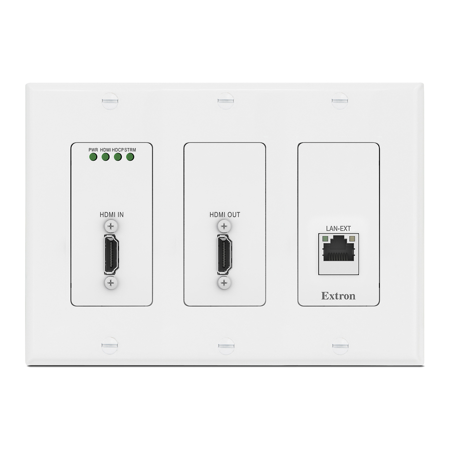
Front Panel
NOTES:
Figure 1 shows a NAV 10E 401 D. The NAV 10E 201 D
•
is similar, the exception is lack of a NAV Extension port
(
).
D
Items
and
•
C
F
removed.
Connectors
A
HDMI input (IN) port —
this port and the HDMI output port (or DVI port, with an
appropriate adapter) of the digital video source.
B
HDMI output (OUT) port
HDMI connector for local loop-through monitoring of the
source signal.
NOTE: See
LockIt
C
Configuration (CONFIG) port —
USB
; the IP address is always
technology
Toolbelt.
LAN - Ext(ension) port (NAV 10E 401 D only) — If desired, connect another networked device to this port (see
D
connector
on page 8 to wire the connector). The port acts as a networked switch to the NAV 10G port (see
page 2).
NAV 10E 401 D and NAV 10E 201 D
NAV 10E 401 D and NAV 10E 201 D
Le
are visible only when the faceplate is
Connect an HDMI cable between
— Connect a display to this female
on page 6 to securely fasten the HDMI connectors to the encoder for
Lacing Brackets
®
Connect a PC into the encoder for configuration of the encoder. The port uses IP over
203.0.113.22 and CANNOT be changed
User Guide at
output continuous invisible light (Class 1 rated), which may be harmful to
émettent une lumière invisible en continu (équipement de classe 1)
E
E E
PWR
HDMI HDCP
STRM
F
F F
HDMI IN
A
A A
Figure 1.
NAV 10E 401 D Front Panel Features
. The Config port is also discoverable via
.
www.extron.com
RESET
ID
HDMI OUT
NAV 10G
LAN - EXT
LNK
ACT
CONFIG
E
C
C C
B B
B
D
D D
A
A
NAV 10E 401 D
only
and
.
B
Ext
on
1
Advertisement
Table of Contents

Related Manuals for Extron electronics NAV 10E 401 D


Summary of Contents for Extron electronics NAV 10E 401 D
- Page 1 The front panel faceplates are in white or black, as appropriate. NOTE: For more information on any subject in this guide, see the NAV 10E 401 D and NAV 10E 201 D User Guide, available at www.extron.com.
- Page 2 (features that are visible only when the faceplate is removed) — • Reset button and LED — This recessed button and LED initiate and display three modes of reset (see the NAV 10E 401 D and www.extron.com NAV 10E 201 D User Guide, available at , for details).
- Page 3 ATTENTION: For the installation to meet UL requirements and to comply with National Electrical Code (NEC), the encoder must • be installed in a UL Listed junction box. The end user or installer must furnish the junction box. It is not included with the unit.
- Page 4 NAV 10E 401 D and NAV 10E 201 D • Setup Guide (Continued) Step 4: Complete the Physical Installation Mount the encoder to the installation surface as follows: NOTE: Extron recommends taking safety precautions to avoid electrostatic discharge issues during installation.
- Page 5 System Operation The encoder can be configured and controlled using embedded web pages or Toolbelt software (see the NAV 10E 401 D and NAV 10E 201 D User Guide, available at www.extron.com). Connection via web pages Connection to the encoder and its embedded web pages can be made via either the front panel configuration (USB) port...
- Page 6 2 2 2 2 2 2 2 2 2 2 2 2 Figure 7. Home Page NOTE: Detailed descriptions of communication, configuration, and monitoring are provided in the NAV 10E 401 D and NAV 10E 201 D User Guide, available at www.extron.com.
- Page 7 Connection settings View and change connection settings as follows: On the home page, click (see figure on page 6) > Settings (2) > (3). The Network Connection Networking Network Connect pane opens (see figure 8), showing protected views of the network connection settings.
- Page 8 Connection Details 5 5 5 LockIt Lacing Brackets ® 3 3 3 Plug the HDMI cable into the panel connection (see , at right). 4 4 4 2 2 2 Loosen the HDMI connection mounting screw from the panel enough to allow the LockIt lacing bracket to be placed over it ( ).
Need help?
Do you have a question about the NAV 10E 401 D and is the answer not in the manual?
Questions and answers