
Subscribe to Our Youtube Channel
Related Manuals for SMC Networks JXC93 Series


Summary of Contents for SMC Networks JXC93 Series
- Page 1 No. JXC※-OMT0002-C Product name 4-axis Step Motor Controller (EtherNet / IP type) MODEL/ Series/ Product Number JXC93 Series...
-
Page 2: Table Of Contents
Contents 1. Safety Instructions ..........5 2. Product Outline ............ 7 2.1 Features ..................7 2.2 How to Order................8 2.3 Product configuration ............... 9 3. Procedures to Trial run ........10 3.1 Checking the contents of the package ......... 10 3.2 Mounting the controller ............ - Page 3 The saved IP address will be lost. But when return to the Enable DHCP from Disable BOOTP/DHCP, it is possible to set the new IP address from BOOTP/DHCP server. 34 5.2 PLC setting (Configuration) ........... 35 5.3 Setting of EtherNet/IP using RSLogix5000 ....
- Page 4 (1) From power on to Return to origin ......... 74 (2) Positioning operation ............75 (3) Pushing operation ............76 (4) HOLD .................. 77 (5) RESET ................77 (6) STOP .................. 79 (7) Area output ................ 80 12. Accessories ............81 12.1 Power cable for main control ..........
- Page 5 Supplement 1.2 Initial setting of LEFS series ......108 Supplement 1.3 Initial setting of LES(H) series ....... 109 Supplement 1.4 Initial setting of LEP series ......109 Supplement 1.5 Initial setting of LEFB series ......110 Supplement 1.6 Initial setting of LER series ......110 Supplement 1.7 Initial setting of LEH series ......
-
Page 6: Safety Instructions
JXC93 Series / Controller 1. Safety Instructions These safety instructions are intended to prevent hazardous situations and/or equipment damage. These instructions indicate the level of potential hazard with the labels of “Caution,” “Warning” or “Danger.” They are all important notes for safety and must be followed in addition to International Standards (ISO/IEC) , and other safety regulations. - Page 7 JXC93 Series / Controller 1. Safety Instructions Caution 1.The product is provided for use in manufacturing industries. The product herein described is basically provided for peaceful use in manufacturing industries. If considering using the product in other industries, consult SMC beforehand and provide specifications or a contract, if necessary.
-
Page 8: Product Outline
2. Product Outline 2.1 Features The JXC93 uses operation instructions to control multiple actuators. The operation instructions are comprised of "step data" information, which contains actuator performance command data such as position, speed, or acceleration, etc. The step data is predefined in the controller setting software. An EtherNet/IP command, which specifies a step data number, is sent to the controller to start the operation based on the step data information. -
Page 9: How To Order
2.2 How to Order How to order is shown below. J X C 9 3 Electric equipment Mounting Controller Direct mounting Controller type DIN rail Ethernet/IP 4 axis type Applicable Actuator Electric Actuator Rod Type LEY Series Electric Actuator Rod Type with Guide LEYG Series Electric Actuator Slider Type LEF Series Electric Slide Table LES/LESH Series Note1) -
Page 10: Product Configuration
2.3 Product configuration Structure of the controller. Ethernet cable Note (Category 5 ● Electric actuator cable or higher) Note2) Note2) EtherNet/IP Note3) To P1、P2 ●Controller Note To ENC ●Actuator cable Options Part No: LE-CP- To USB (Robotic type cable) ... -
Page 11: Procedures To Trial Run
3. Procedures to Trial run Install, wire, set and perform a trial run for the controller referring to the procedure below when using the product for the first time. Supply power. Check the contents Mounting the Software Wiring and Start-up of of the package controller Installation... -
Page 12: Mounting The Controller
3.2 Mounting the controller Refer to 4.4 Mounting for instructions on how to mount the controller. 3.3 Install the setting software and the driver Install the controller setting software and driver software on the PC to be used. For details, refer to the Installation Manual for the controller setting software (No.SFOD-OMT0008). 3.4 Wiring and connection Connect the cables to the controller. -
Page 13: Start-Up Of Controller Setting Software
(2) Start-up of controller setting software Using a PC with the controller setting software installed, start the application "SMC / JXC Controller" to start the setting software. If the controller setting software is installed with the default setting, an icon will be created on the desk top. -
Page 14: Alarm Check
After the initial title window is displayed, the following main window will be displayed. The communication status between the controller and PC is indicated at the bottom of the main window. Display Details Off-line state On-line state When the PC is able to communicate with the controller, "On-line" status is established automatically. -
Page 15: Parameters And Step Data
3.6 Parameters and Step data When using for the first time or after changing the connected actuator, or when the settings of the controller or connected actuator have been changed, it is necessary to review the set parameters and step data. It is possible to display parameters and step data as shown below. - Page 16 Input the partnumber of the actuator to be used in the “Search from Part No. area”. A list of part numbers of the actuators matching the conditions will be displayed by clicking the "Result" button. Select the actuator to be connected. Result Search from Part No.
- Page 17 Select the check box for the axis for which parameters are to be input (one or more boxes are possible to be selected). Select the "Execute" button. Axis parameters will be displayed in the Actuator selection window. The values input here are for display only, and are not written to the controller.
-
Page 18: Setting Parameters
(2) Setting parameters Set the parameters such as for valid axis and electronic gear. Check the parameters below and change them if necessary. For other items, refer to section 9. Settings and Data Entry. Parameter name Input range Outline Max step 512 or 2048 Maximum step data. - Page 19 After setting parameters, select the "Download" button in the parameter window. Parameters in the parameter window will be written to the controller. Writing is completed when the progress bar disappears and then the setting software is ready to operate. It is necessary to turn off the power to the controller and turn it on again. The downloaded parameters will become valid after turning the power on again.
-
Page 20: Step Data Settings
(3) Step data settings Select "View(V)" at the top of the main window, and select "Step Data". The Step data window will be displayed. Download Movement mode Area to input numerical data Select the “▼” button for the movement mode for the axis of the step number to be set. Select the movement mode shown in the list. -
Page 21: Check Using Jog Operation
3.7 Check using JOG operation (1) Change to Remote mode Change the mode to Remote mode at the top of the main window. The Servo will be turned on by selecting Remote mode. Confirm that the Servo is ON. (Confirm SVRE ON in the status window.) Select "View(V)"... -
Page 22: Return To Origin
(2) Return to origin Select "View(V)" at the top of the main window, and select "Teaching". The teaching window will be displayed. Return to Origin tab All axes Return to Origin Select the “Return to Origin” tab. Select "Return to Origin(●)” or "All axes Return to Origin". When the return to origin setting is completed, SETON is ON. -
Page 23: Jog Or Inching
(3) JOG or Inching Select the “JOG” or “Inching” tab. JOG tab Inching tab Speed Travel distance +/- button (a) JOG Set the "Speed". The Position will move in the "+" or "-" direction as long as the "+" or "-" button is pressed. -
Page 24: Operation Test Using Test Drive
3.8 Operation test using Test Drive Select "View(V)" at the top of the main window, and select "Test Drive". The Test Drive window will be displayed. It is possible to test the set step data in a specified order. (1) Test Drive setting Set the order of the step data number for testing in the test drive list window. -
Page 25: Return To Origin
(3) Return to origin Confirm that SVRE is ON, refer to section 3.7 (1) Change to Remote mode. Then, select "All axes Return to Origin", and perform the “Return to origin” operation. (4) Test drive starts Confirm that SETON is ON, refer to section 3.7 (2) Return to origin. Test drive starts by pressing the "Go"... -
Page 26: Ethernet/Ip Communication Setting And Checking
3.9 EtherNet/IP communication setting and checking (1) Controller setting It is necessary to set the IP address using the rotary switches of the controller. Refer to 5.1 Controller setting (IP address setting) for details. (2) PLC set up It is necessary to set the PLC parameters. This is possible to do by using an EDS file for the configuration of the controller. -
Page 27: Product Specifications
4. Product Specifications 4.1 Basic Specifications Item Specifications Number of axes per controller Max. 4-axis Controlled motor Step motor (servo 24 VDC ) Encoder Incremental phase A / B (Encoder resolution 800 pulse / rotation) Main control power supply Power supply voltage: 24VDC+/-10% Max. - Page 28 4.2 EtherNet/IP Specifications Item Specifications Protocol TM note1) EtherNet/IP (Conformance test version CT12) Communication speed 10Mbps/100 Mbps (automatic negotiation) Communication method Full duplex/ Half duplex (automatic negotiation) Setup file EDS file Occupied area Input 16 bytes / Output 16 bytes Manual setting by switches: From 192.168.1.1 to 254 IP address setting range Via DHCP server: Arbitrary address...
-
Page 29: Parts Description
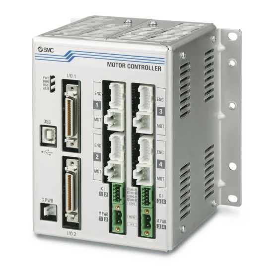
4.3 Parts Description Detail of the controller parts. (10) (15) (16) (11) (12) (17) (21) (18) (19) (20) (13) (14) Display Description Details Power supply OFF Power supply LED (green) Green LED is ON Power supply ON Stop Operating LED (green) Green LED is ON Operation by EtherNet/IP Green LED is flashing... - Page 30 Table below shows details of LED. Details Main control power supply is OFF or IP address is not set. EtherNet/IP Green LED is ON Connection is established. communication Green LED is flashing Connection is not established. status Red LED is flashing Connection time out Red LED is ON IP duplicated...
-
Page 31: Dimensions
4.4 Dimensions (1) Direct mounting (2) DIN rail mounting -30- No. JXC※-OMT0002-C... -
Page 32: Mounting
4.5 Mounting (1) Mounting There are two ways to mount the controller. (Direct mounting with screws and DIN rail mounting) Controller mounting methods are shown below. (a) Direct Mounting with four M5 screws Mounting screw (M5) 4pcs. (prepared by customer) (b) DIN rail mounting The figure on the right shows how to mount the DIN rail mounting brackets. -
Page 33: Grounding
Part A Part B Holding screw M5X14 (2) Grounding Fit the grounding cable with crimped terminal between the M3 screw and shakeproof washer as shown below and tighten the screw. Shakeproof washer Grounding cable (with crimped terminal) M3 screw Caution The cable with crimped terminal and shakeproof washer must be prepared by the user. -
Page 34: Mounting Location
Caution (1) A dedicated ground connection must be used. Grounding should be to a D-class ground (ground resistance of 100Ω or less). (2) The cross sectional area of the grounding cable should be 2mm minimum. The grounding point should be as near as possible to the controller, to keep the grounding cable as short as possible. -
Page 35: Initial Setting Method
5. Initial Setting Method Initial setting of the controller and PLC is necessary for the communication with EtherNet/IP. 5.1 Controller setting (IP address setting) IP address setting is necessary to distinguish the controller on the EtherNet/IP network. IP address is set by the rotary switches of the controller. -
Page 36: Plc Setting (Configuration)
5.2 PLC setting (Configuration) Setting (configuration) of the PLC is necessary to establish EtherNet/IP communication with the controller. It is possible to use an EDS file for the configuration of the controller. It is possible to download the EDS file designated for this controller by the URL shown below. It is possible to download by the URL shown below the icons designated for this controller. -
Page 37: Setting Of Ethernet/Ip
5.3 Setting of EtherNet/IP using RSLogix5000 Method to connect the JXC93 to the Rockwell Automation EtherNet/IP module (master) is shown below. Refer to the Operation Manual of the for the detailed operation. RSLogix5000 : This figure shows the display of Rockwell Automation software, RSLogix5000 •Select [EtherNet/IP module] in [I/O Configuration] folder, then select [New Module]. - Page 38 •[Module Properties] screen is displayed. Perform each setting. (1) Name: Enter the required unit name. (2) Comm Format: Select the data format of Connection Parameters. (3) IP Address: Enter the IP address setting for the JXC93. (4) Assembly Instance: Perform setting as shown below. Item Decimal Comm Format...
-
Page 39: Power Supply Connector
6. Power supply connector 6.1 Connector specifications The power supply connector type included is shown below. (1) Main control power supply connector: C PWR Brown Terminal Function Description +24V +24V Main control power supply (+) Power supply (+) for main control. 24-0V 24-0V Main control power supply (-) -
Page 40: Motor Control Power Supply Connector: Ci
(3) Motor control power supply connector: CI Terminal Function Functional explanation Motor control power C24V Power supply side (+) for motor control. supply (+) Release the stop status (+) of Axis 1 or Axis 3. EMG1/EMG3 Stop(+) (Normal operation by applying 24V.) Release the stop status (+) of Axis 2 or Axis 4. -
Page 41: Wiring
6.2 Wiring Connect the main control power supply, motor drive and motor control power supply while referring to (1) to (3) below, and then insert into the controller C PWR, Cl and M PWR. (1) Wiring of the power supply connector Connect the main control power supply 24V and 0V to the main control power supply connector +24V and 24-0V terminals. -
Page 42: Wiring Of The Stop Switch
(2) Wiring of the stop switch A Stop switch must be installed by the user to stop the actuator in abnormal situations. The actuator stops its operation when the external shutdown switch is activated. - Stop (Stop switch) To stop the controller, connect the stop switch (B contact) between the motor drive and motor control power supply and the EMG terminal of the motor control power supply connector. - Page 43 Motor power shutdown (relay contact) If it is necessary to have a circuit to shutdown the motor drive power externally, relay contacts should be placed between the motor drive and motor control power supply and the M24V of the motor control power supply connector and the EMG terminal of the motor control power supply connector.(Circuit example: The Figure below shows the stop status) 24 VDC The stop is...
-
Page 44: Ethernet/Ip Communication Connector
7. EtherNet/IP communication connector EtherNet/IP communication connector (P1 and P2) specifications are shown below. Terminal Function Functional explanation Sending (+) Sending (-) Receiving (+) Receiving (-) Shell -43- No. JXC※-OMT0002-C... -
Page 45: Memory Map
8. Memory Map 8.1 Memory allocation Table below shows the allocation of memory. (1) PLC input port signals (from the controller to PLC) Byte AREA4 AREA3 AREA2 AREA1 BUSY4 BUSY3 BUSY2 BUSY1 ALARM4 ALARM3 ALARM2 ALARM1 INP4 INP3 INP2... - Page 46 Signal name Description OUT0 Output the number of ongoing step data. OUT1 When the operation is started and the DRIVE is turned ON, a Bit No. OUT2 corresponding to the number of the active step data will be output from OUT3 these terminals.
-
Page 47: Plc Output Port Signals (From The Plc To Controller)
(2) PLC output port signals (from the PLC to controller) Signal name Description Step data instruction Bit No.(Standard: When 512 is used) Step data instruction Bit No. (Input is instructed in the combination of IN0 to IN8.) Ex. (Assign step data No.3)→ “00000011” ←... - Page 48 Signal name Description Alarm reset and interruption of operation When RESET is turned ON during operation, the speed decreases at maximum deceleration of the basic parameter until the actuator stops. INP and OUT0 to OUT10 are OFF. (However, if the actuator is stopped within the in-position range, the INP will be turned ON).
-
Page 49: Setting Data Entry
9. Setting Data Entry In order to move the actuator to a specific position, it is necessary to program the parameters and step data in the controller using a PC with the controller setting software installed. The data entered using the controller setting software will be stored in the memory of the controller. 9.1 Profile parameter The “Profile parameter”... -
Page 50: Basic Parameter
9.2 Basic parameter The “Basic parameter” is the data to define the operating conditions of the controller, conditions of the actuator, etc. Activation: “XX” = Become effective just after storing in the controller “X” = Become effective after restarting the controller “-“... - Page 51 Description Input range Explanation Write Define the electronic Gear. - Undefined No.11: "Electronic Gear (numerator)" - Undefined No.12: "Electronic Gear (denominator)" This product controls the LE series motor (800 pulse per rotation). Please refer to Supplement 1. Actuator Specifications for the travel distance of the motor per rotation.
-
Page 52: Return To Origin Parameter
9.3 Return to origin parameter The “Return to origin parameter” is the setting data for the return to origin operation. Activation: “XX” = Become effective just after storing in the controller “X” = Become effective after restarting the controller “-” = The parameter cannot be changed (fixed value). Description Input range Explanation... -
Page 53: Step Data
9.4 Step data A “step data” is the data set to define the movement of the actuator. Total of 512 step data (9 attributes per step) are possible to handle by this controller. (When "2048" is set for "Max step data Num"... - Page 54 Description Input range Explanation “Stroke (-)” to “Stroke Set the target position (Unit: mm) (+)” in the basic Position Refer to (1) to (5) on page 53 for position setting for movement mode. parameters Set the acceleration to reach to travel speed. (Unit mm/s 1 to “Max ACC/DEC”...
-
Page 55: Abs
Different settings for each movement mode are shown below. (1) ABS In-position Step Movement Speed Position Acceleration Deceleration Pushing Area 1 Area 2 Axis (mm) mode (mm/s) (mm) (mm/s (mm/s Selection (mm) (mm) Axis 1 Absolute 200.00 1000 1000 12.0 Axis 2 Absolute 100.00... -
Page 56: Cir-R / Cir-L
(4) CIR-R / CIR-L Step Movement Speed Position Acceleration Deceleration Pushing Area 1 Area 2 In-position Axis mode (mm/s) (mm) (mm/s (mm/s Selection (mm) (mm) (mm) Axis 1 CIR-R 100.00 1000 1000 Axis 2 CIR-R 100.00 Note1) Axis 3 50.00 Note1) Axis 4 50.00... -
Page 57: Description Of Operation
10. Description of operation 10.1 Return to origin After entering the step data, it is necessary to perform a return to origin operation before positioning the actuator. (To ensure the position of origin) The actuator moves in the Return to origin direction (*dependent on the actuator) from the initial position at the moment of power-on. -
Page 58: Positioning Operation
10.2 Positioning Operation When the "Pushing selection" step data is "0" for a Positioning operation. The actuator moves to the target position specified by the step data “Position.” ● ● Positioning Operation (Example) Positioning operation [Speed/Position] (Example) Speed Step Data "In-position"... - Page 59 Operation (Example) Load Actuator Load Actuator Motor Motor Axis 1 Axis 2 50mm 60mm 100mm 50mm 60mm 100mm Origin position Origin position End position End position Actuator Load Actuator Load Motor Motor Axis 3 Axis 4 50mm 60mm 100mm 50mm 60mm 100mm Origin position End position...
- Page 60 Flow chart (Reference) (1) Select Step No.1. (Turn IN0 ON.) ↓ (2) Turn the "DRIVE" ON. ↓ Controller The Motor starts to move to the position set in Step No.1. ↓ (3) Step No.1 output turns on. Signal name (OUT0 is turned ON) (2), (6), (10), (14) ↓...
-
Page 61: Pushing Operation
10.3 Pushing Operation When the "Pushing selection" step data is "1", for a pushing operation. First a positioning operation is performed to the "Target" position and according to the "Speed" set in the step data. The pushing operation starts from this "Position" for a maximum distance defined by the "Positioning width". - Page 62 (3) Movement of the workpiece after completing the pushing operation (a) The workpiece moves in the pushing direction. After completing the pushing operation, if the reaction force from the workpiece becomes smaller, the actuator may move with a force smaller than that specified in the “Trigger level” of the profile parameter.
- Page 63 Example) After a Return to origin, move 4 axes from the origin to 100mm position at 100mm/s. From the 100mm position, pushing for a maximum of 5mm at a speed of 10mm/s (profileparameter: Pushing speed) at 50% or lower of thrust (profile parameter: Pushing force) (Step No.1).
- Page 64 Flow chart (Reference) (1)Select Step No.1. (Turn IN0 ON.) ↓ (2)Turn the "DRIVE" input ON. ↓ The Motor starts to move to the position set in Step No.1. ↓ (3) Step No.1 is turned ON. (OUT0 is turned ON) ↓ Controller (4) “INP”...
-
Page 65: Linear Interpolation
10.4 Linear interpolation Move axes in a straight line from the current position at a defined "Speed" (composite speed for the speed of each axis) to a "Position" set in the step data. The speed of each axis is calculated using the formulae below. - Page 66 Example) After a Return to origin, move from the origin position at 100mm/s of composite speed to a point at 100mm on Axis 1 and 100mm on Axis 2 (Step No.1). Then, move from the current position at 50mm/s of composite speed to a point at 100mm on Axis 1 and 50mm on Axis 2 (Step No.2).
- Page 67 Flow chart (Reference) (1) Select Step No.1. (Turn IN0 ON.) ↓ (2) Turn the DRIVE ON. ↓ Controller The Motor starts to move to the position set in Step No.1. ↓ (3)Step No.1 is turned ON. Signal name (OUT0 is turned ON) (2)(6)(10)(14) ↓...
-
Page 68: Circular Interpolation
10.5 Circular interpolation Circular interpolation by specifying the target coordinate (relative) and centre coordinate (relative) referring to Axis 1 as the X axis and Axis 2 as the Y axis. Clockwise circular interpolation is in CIR-R mode and counterclockwise is in CIR-L mode. Each axis travels at a speed lower than the composite speed. - Page 69 Caution Setting of the electronic Gear is necessary when actuators with different a lead are used. If the electronic gear is not set, the step data operation may not be produced. Refer to section 3.6 Parameters and Step data for the calculation of the electronic Gear. Caution When mode CIR-R/L is repeatedly used, there will be an accumulated error in the achieved position due to the motor resolution.
- Page 70 Example) After a Return to origin, move from the origin position at 100 mm/s to a point 30mm on Axis 1 and 10mm on Axis 2 (Step No.1). Move from the current position using counterclockwise circular interpolation movement at 100 mm/s composite speed to a point 0mm on Axis 1 and 40mm on Axis 2 (Step No.2: Centre position 0mm on Axis 1, 20mm on Axis 2).
- Page 71 Flow chart (Reference) (1)Select Step No.1. (Turn IN0 ON.) ↓ (2)Turn the DRIVE ON. ↓ Controller The Motor starts to move to the position set in Step No.1. ↓ Signal name (3)Step No.1 is turned ON. (2)(6)(10)(14)(18)(22) (OUT0 is turned ON) ↓...
-
Page 72: Speed Tuning Control Operation
10.6 Speed tuning control When an (main) axis is delayed due to external load, the speed of other (slave) axes is controlled. Not the synchronization of the position of the main axis and slave axis. Pushing operation cannot be used. Caution (1) Actuators with a different lead cannot be used. - Page 73 Example) After returning to origin, move all axes by speed tuning control from the origin to 200 mm point at 100 mm/s. (Step Data No.0 is used for this operation). Step Data Setting Example Step Movement Speed Position Acceleration Deceleration Pushing Area 1 Area 2...
-
Page 74: Plc Output Signal Response Time
10.7 PLC output signal response time The PLC output signal response time includes the following factors. 1) Controller signal scan time 2) Delay due to signal analysis 3) Delay due to command analysis Leave an interval of 40ms or more between signals and maintain the state of the signal for 40ms or more, because PLC processing delays and controller scanning delays could occur. -
Page 75: Operation Instructions
11. Operation Instructions 11.1 Outline of the Operation instruction The controller is possible to operate by selecting the step data in the controller using the EtherNet/IP. Refer to the next section for details of the input/ output signal timing and control procedures. 11.2 Operation procedure Please refer to the following “Procedure”... -
Page 76: Positioning Operation
(2) Positioning operation - Procedure - - Timing chart - (a) Output the step data Power supply No.(INx). ↓ Min.15ms (b)Turn the DRIVE is ON. The step data No. (OUTx) will be Previous step No. input. OUTx ↓ Current step No. (c) The BUSY turns ON and INP turns OFF. -
Page 77: Pushing Operation
(3) Pushing operation - Procedure - - Timing chart - (a) Output the step data No. Power supply (INx). ↓ Min.15ms (b) Turn the DRIVE ON. The step data No. Previous step data No. (OUTx) will be input. Current step data No. ↓... -
Page 78: Hold
(4) HOLD - Procedure - - Timing chart - (a) The HOLD is turned ON during a movement operation (when the BUSY is ON). ↓ (b) The BUSY turns OFF. (The actuator will stop). Previous step data No. ↓ Current step data No. (c) The HOLD turn OFF. - Page 79 [Reset of operation] - Procedure - - Timing chart - (a) The RESET is turned ON during a movement operation (when the BUSY is ON). ↓ (b) The BUSY is OFF and OUTx is Current step data No. Previous step data No. OFF.
-
Page 80: Stop
(6) STOP - Procedure - Timing charge - (a) The Stop (EMG) input is OFF during an operation (when the BUSY is ON). (Stop command) ↓ (b) The ESTOP will turn OFF. ↓ (c) The BUSY will turn OFF. (The actuator will stop). -
Page 81: Area Output
(7) Area output -Procedures- (a) Output the Step data No. (INx). (b) Turn the "DRIVE" ON. Step data No. 1 (OUTx) will be input. (c) The BUSY will turn ON and INP will turn OFF (the positioning operation will starts). (d) The AREA of step data No.1 turns ON (at 150mm from the origin point). -
Page 82: Accessories
12. Accessories 12.1 Power cable for main control JXC-C1 (1500) Cable colour: Blue (0V) Cable colour: Brown (24V) Cable specification Item Specifications Cable length 1.5m Stranded wire --> AWG20 (0.5mm Electric wire O.D. of sheath -->1.76 mm size +24V: Brown Wire sheath 24-0V: Blue colour... -
Page 83: Actuator Cable (5M Or Less)
12.3 Actuator cable (5m or less) Terminal L E - C P - - Signal name Terminal number Cable colour number Brown Cable length [L] Orange 1.5m Yellow COM-A/COM Green Blue COM-B/ - Shield Terminal Cable colour number Brown Cable type Black Robotic type cable Black... -
Page 84: Actuator Cable [For Sensor/ With Lock (5M Or Less)]
12.5 Actuator cable [For sensor/ with lock (5m or less)] Terminal Signal name L E - C P - - B - Cable color Terminal number number Brown Cable length [L] Orange Yellow 1.5m COM-A/COM Green COM-B/ - Blue Shield Cable color Terminal number Brown... -
Page 85: Controller Set Up Kit
12.7 Controller Set up kit JXC-W1 Contents (1) Controller set up software (CD-ROM) Product No.: JXC-W1-1 (2) USBcable (A-B type) Product No.: JXC-W1-2 Controller Operating environment Windows®7 (32bit or 64bit) Microsoft .NET Framework 2.0 is necessary. Compatible OS Note1) Windows®8.1 (32bit or 64bit) Microsoft .NET Framework 3.5 is necessary. Hard disk 50MB or more space... -
Page 86: Alarm Detection
13. Alarm detection The details of an alarm generated are possible to check using a PC (with controller setting software). Please refer to the controller setting software manual (No. SFOD-OMT0012) to check the details of the alarms. When an alarm is generated, deactivate the alarm after troubleshooting and correcting the error with reference to section 13.2 Alarms and countermeasures. -
Page 87: Alarms And Countermeasures
13.2 Alarms and countermeasures (1) Controller alarm Name of the controller How to setting Alarms and countermeasures deactivate software (code) < Details > An alarm is generated when the Drive operation [DRIVE] is ON when the DRIVE is ON RESET servo [SVRE] is OFF after a Return to origin. - Page 88 Name of the controller How to setting Alarms and countermeasures deactivate software (code) Turn off the < Details > main Abnormality concerning FROM is confirmed. control and FROM Error motor (0-912) control <Countermeasure> power Please contact SMC. supplies. < Details > Turn off the An alarm is generated when an abnormality is found in the Modbus main...
- Page 89 (2) Driver alarm Name of the controller How to setting Alarms and countermeasures deactivate software (code) < Details > The step data or parameter is incorrect for the following parameter assignable range. [Settable range] (1) Pushing force ≥ Trigger level (2) Pushing force >...
- Page 90 Name of the controller How to setting Alarms and countermeasures deactivate software (code) < Details > Return to origin was not completed within the set time. <Countermeasure> Return to ORIG did not - If the ORIG mode is "0: Pushing Return to origin", the controller RESET complete in the parameter “model”...
- Page 91 Name of the controller How to setting Alarms and countermeasures deactivate software (code) < Details > The origin sensor does not respond correctly when a Return to origin operation is performed with the origin sensor. An Alarm is generated depending on the set value of the Return to origin parameter. Return to origin parameter value Alarm conditions...
- Page 92 Name of the controller How to setting Alarms and countermeasures deactivate software (code) < Details > The motor speed has exceeded the specified value, possibly due to an external force, etc. RESET <Countermeasure> Speed Make improvements to ensure that the motor speed will not exceed the exceeded set SVON is maximum speed of the actuator.
- Page 93 Name of the controller How to setting Alarms and countermeasures deactivate software (code) < Details > The power supply voltage for motor control detected by the controller is outside of the specified range. <Countermeasure> Check the motor control power supply voltage connected to the controller. Caution If a single power supply is used for both the control power and the motor power, or the power supply is an “inrush current protection...
- Page 94 Name of the controller How to setting Alarms and countermeasures deactivate software (code) Turn off the < Details > main An abnormality occurred in communication with the encoder. control and Encoder error motor (1-192) control <Countermeasure> power Check the actuator cable connection. supplies.
-
Page 95: Common Precautions For Wiring And Cable
14. Common Precautions for wiring and cable Warning 1. Adjustment, mounting, inspection or wiring should never be carried out before disconnecting the power supply to the product. Electric shock, malfunction and damage can result. 2. Do not disassemble the cable. Use only specified cables. 3. -
Page 96: Electric Actuators / Common Precautions
15. Electric Actuators / Common Precautions 15.1 Design and Selection Warning 1. Read the Operation Manual before using the product. Handling or usage/operation other than that specified in the Operation Manual may lead to breakage and product failure. Any damage attributed to use beyond the specifications is not guaranteed. 2. -
Page 97: Mounting
15.2 Mounting Warning 1. Read and understand the Operation Manual before installing and operating the product. Keep the manual in a safe place for future reference. 2. Observe the tightening torque for the mounting screws. Tighten screws to the recommended torque for mounting the product. 3. - Page 98 6. In the case of the actuator that has a servo motor (24VDC), the “motor phase detection step" is done by inputting the servo on signal just after the controller power is turned on. The “motor phase detection step” moves the table/rod for the distance of one screw-lead maximum. (The motor rotates in the reverse direction if the table hits an obstacle such as the end stop damper.) Take the “motor phase detection step”...
-
Page 99: Operating Environment
15.4 Operating environment Warning 1. Avoid use in the following environments. a) Locations where a large amount of dust and cutting chips are airborne. b) Locations where the ambient temperature is outside the range of the temperature specification (refer to specifications). c) Locations where the ambient humidity is outside the range of the humidity specification (refer to specifications). -
Page 100: Precautions For Actuator With Lock
Caution 1. Perform maintenance inspection according to the procedure indicated in the Operation Manual. Incorrect handling can cause an injury, damage or malfunction of equipment and machinery. 2. Removal of product When equipment is serviced, first confirm that measures are in place to prevent dropping of work pieces and run-away of equipment, etc, then cut the power supply to the system. -
Page 101: Controller And Peripheral Devices / Specific Product Precautions
16. Controller and Peripheral Devices / Specific Product Precautions 16.1 Design and selection Warning 1. Use the specified voltage. Otherwise, malfunction and damage to the controller may result. If the applied voltage is lower than the specified voltage, it is possible that the load cannot be moved due to an internal voltage drop. -
Page 102: Handling Precautions
16.2 Handling Precautions Warning 1. The inside of the controller and its connector should not be touched. It may cause an electric shock or damage to the controller. 2. Do not perform operation or setting of this equipment with wet hands. It may cause an electric shock. -
Page 103: Mounting
16.3 Mounting Warning 1. The controller and its peripheral devices should be installed on a fire-proof material. Direct installation on or near a flammable material may cause fire. 2. Do not install this product in a location subject to vibration and impact. A failure and malfunction can result. -
Page 104: Power Supply
16.5 Power supply Caution 1. Use a power supply with low noise between lines and between power and ground. In cases where noise is high, use an isolation transformer. 2. The power supplies for the controller power and the I/O signal power should be separate, and both Power supplies should not be of the “in-rush current limiting type”. -
Page 105: Troubleshooting
17. Troubleshooting Refer to the table below for troubleshooting. When none of the causes in the troubleshooting are possible to be confirmed, it is presumed that the product is faulty and normal operation could only be recovered by the replacement of a part. It is possible that this product may be damaged due to the operating conditions (applications). - Page 106 Possible Problems Investigation method Countermeasures causes Correct the wiring so that the input/ output Check that the wiring is connected of each signal is performed appropriately. correctly? Prepare a separate power supply for the Incorrect Refer to the controller operation manual to main control, motor drive and motor control, wiring confirm wiring, and check for broken wires...
- Page 107 Possible Problems Investigation method Countermeasures causes Check that the controller parameters Check that the controller parameter matches with the actuator product Unsuitable settings for the product model and power number. specification supply specification are appropriate for the Check that the power supply specification actuator connected.
-
Page 108: Position / Speed Problems
17.2 Position / Speed problems Possible Problems Investigation method Countermeasures causes Incorrect For a pushing operation, repeat the Return to Check the actuator operation (if foreign origin origin operation several times to check that matter is caught in the product etc.). position the actuator returns to the origin correctly. -
Page 109: Supplement 1. Actuator Specifications
Supplement 1. Actuator Specifications Supplement 1.1 Initial setting of LEY/LEYG series Model LEY16/LEYG16 LEY25/LEYG25 LEY32/LEYG32 LEY40/LEYG40 Lead symbol Lead [mm] Stroke (mm) Max. speed [mm/s] Min. speed [mm/s] (Independent and interpolation) Min. speed [mm/s] (Speed tuning control ) Supplement 1.2 Initial setting of LEFS series Model LEFS16 LEFS25... -
Page 110: Supplement 1.3 Initial Setting Of Les(H) Series
Model LEFS40 Lead symbol Lead [mm] Stroke (mm) 1200 1000 1100 1200 1000 1100 1200 Max. speed [mm/s] Min. speed [mm/s] (Independent interpolation) Min. speed [mm/s] (Speed tuning control) Supplement 1.3 Initial setting of LES(H) series Model LES(H)8 LES(H)16 LES(H)25 Lead symbol Lead [mm] Max. -
Page 111: Supplement 1.5 Initial Setting Of Lefb Series
Supplement 1.5 Initial setting of LEFB series Model LEFB16 LEFB25 LEFB32 Lead symbol Lead [mm] Max. speed [mm/s] 1100 1400 1500 Min. speed [mm/s] (Independent and interpolation) Min. speed [mm/s] (Speed tuning control) Supplement 1.6 Initial setting of LER series Model LER10 LER30... - Page 112 Model LEHF10 LEHF20 LEHF32 LEHF40 Lead symbol Lead [mm] 40/15 50/15 70/16 70/16 (2.667) (3.333) (4.375) (4.375) Max. speed [mm/s] Min. speed [mm/s] (Independent and interpolation) Min. speed [mm/s] (Speed tuning control) Model LEHS10 LEHS20 LEHS32 LEHS40 Lead symbol Lead [mm] 255/76 235/56 235/40...
- Page 113 Revision history No.JXC※-OMT0002 First edition: October 2015 No.JXC※-OMT0002-A Contents are added: December 2015 No.JXC※-OMT0002-B Contents revised in several places: March 2016 No.JXC※-OMT0002-C Revised 10.6 Speed tuning control :Feb 2019 (Rivised Synchronous to speed tuning control) 4-14-1, Sotokanda, Chiyoda-ku, Tokyo 101-0021 JAPAN Tel: + 81 3 5207 8249 Fax: +81 3 5298 5362 http://www.smcworld.com Note:...
Need help?
Do you have a question about the JXC93 Series and is the answer not in the manual?
Questions and answers