Advertisement
Advertisement
Table of Contents

Summary of Contents for JOBO JOBOBIKE Bruno
- Page 2 Please read this manual carefully and follow the instruction when assembling this bike. If you still have any questions after reading this manual, please visit our website, send us an email, or give us a phone call. JOBO Europe sp. z o.o. ul. Gromadzka 5 505-806 Sokołów...
-
Page 3: Manual Use Instruction
Manual use instruction This manual contains the details of the equipment, operation, and maintenance of the product along with our advice to you. Before you start using your new bike, it is necessary to read through the instructions. If you are unclear about any steps, you can always find additional information and instructions on our website: www.jobobike.pl The purpose of this manual is to inform you the safe ways to operate this bike. -
Page 4: Table Of Contents
Table of Content Manual use instruction............................2 General Information............................4 Assembly Instructions............................9 Battery Charging..............................21 Operation.................................25 Maintenance..............................32 Tubleshooting..............................37 Warnings and Safety............................40 After Sales Policy .............................44... -
Page 5: General Information
General Information Vehicle Category BRUNO E-bike is a 250 watt (W) e-bike. E-bikes should be operated according to legal regulations made by laws of each country. You are obliged to follow the regulations of your country. Mandatory Equipment and Locations Before each ride, make sure that you are following all laws pertaining to using an E-bike in your region with all required safety equipments set up. - Page 6 NOTICE: A critical aspect of assembling your JOBOBIKE is securing the front and back wheel and checking the tightness of the rear wheel axle nuts. All JOBOBIKEs use quick-release front wheels with bolt on rear wheels. These mechanisms may become less secured during shipment and after use.
- Page 7 Quick Release Levers Quick release levers are for securing the seatpost and the front and back wheel to the bike. They allow the user to remove the front wheel and to adjust the seatposts without tools. Since quick release levers could be loosened during transportation, or accidentally between or during rides, it is important that you regularly check to ensure these components to be properly secured.
- Page 9 Accessory name Accessory name Accessory name Saddle Tyre Stem Seat post Chain Shifter Seat post clamp Middle motor Brake lever Rear brake Crank Grips Brake rotor Pedal Display Freewheel Front brake Frame Rear Derailleur Thru axle Battery Kickstand Suspension fork Reflector Front light Headset...
-
Page 10: Assembly Instructions
Assembly Instructions NOTICE: The following steps are only a general guide to assist the assembling process of your E-bike and is not a complete or comprehen- sive manual of all aspects of assembly, maintenance, and repair. We recommend you to consult a certified bike mechanic to assist in the as- sembly, repair, and maintenance of your E-bike. - Page 11 Place the handlebar on the stem correctly. Trace the front brake cable directly up from the front brake caliper to the left handlebar and ensure that the cables and wires are not twisted. Centre the handlebar and tighten the four stem faceplate bolts evenly.
- Page 12 Install the thru axle...
- Page 13 Remove the thru axle...
- Page 14 When properly installed, the front wheel should be at the center of the front fork, the brake rotor should be between the brake pads in the brake caliper, and the quick release lever should be fully se- cured. Make sure that the front wheel and quickr elease lever are properly secured before moving on to the next step NOTICE: For safety reasons, the quick release lever MUST be locked tightly enough.Never touch the brake rotor, especially when the wheel and/or bike is in...
- Page 15 Step 5 Install the pedals. Locate the pedal that has a smooth pedal axle exterior and a“R” stamp at the right end. The right pedal goes onto the crank on the right side of the bike (which has the drivetrain gears and locates at the rider’s right side when riding).Carefully thread the right pedal onto the crank on the right side of the bike by hand.
- Page 16 Step 6 Inflate the tyres. Check that the tyre beads and tyres are evenly seated on the rims. Use a pump with a Schrader valve and pressure gauge to inflate each tyre to the recommended pressure value indicated on the tyre sidewall, 35-60 psi (2.5 –...
- Page 17 Step 9 Ensure all hardware is tightened properly following recommended torque values. Recommended Torque Values Hardware Location Hardware Torque Required (Nm) Handlebar Area Handlebar Stem Clamp Bolts Handlebar Area Handlebar Stem Faceplate Bolts Handlebar Area Brake Lever Clamp Bolt Handlebar Area Shifter Clamp Screw Brakes Calliper Adapter to Frame...
- Page 18 Step 10 Review the remainder of the manual. Once the bike has been assembled following the instructions above, read, understand, and follow the procedures outlined in the remainder of the manual before operating the bike. NOTICE: If you have any questions regarding the assembly of your bike, contact Jobobike If you are unsure if all the assembly steps in the assembly video are performed properly, or you are unable to view the assembly video, please consult a certified local bike mechanic for assistance in addition to contacting Jobobike for help.
- Page 19 Rider’s Comfort Generally, for the most comfortable riding position and the best pedaling efficiency, the seat height should be set correctly in relation to the rider’s leg length, as described in the Adjusting the Seat Height section, allowing the knees to be slightly bent with the ball of the foot still on the pedal when the pedal is at the lowest point at the bottom of each stroke.
- Page 20 NOTICE: Ensure that both the seatpost and seat are both properly adjusted before riding. DO NOT raise the seatpost beyond the minimum insertion marking etched onto the seatpost tube (as shown at figure). If the seatpost projects from the frame beyond these markings (shown far right), the seatpost and the frame may break, which could cause a rider to lose control and all.Ensure that the minimum insertion markings on the seatpostare inside the seat tube of the frame 3.
- Page 21 NOTICE: Prior to first use, be sure to tighten the seat clamp via the seat adjustment bolt properly. A loose seat clamp or seatpost adjustment bolt can cause bike/property damage, loss of control, a fall, seri- ous injury or death. Periodically check to make sure that the seat clamp is properly tightened.
-
Page 22: Battery Charging
Rider weight (lbs) Suggested air pressure (psi) <140 50-70 140-160 70-80 160-180 80-90 180-200 90-100 >200 Do NOT exceed 100 psi attery Charging Charging Procedure: The battery can be charged both when it is located inside of the frame or when you take it out of the frame. - Page 23 5. When the battery is outside of the E-bike: a. Use the key to unlock battery and pull it out of the frame. b. Place battery in a secure place and plug the charger into the charging port first; then connect it to a power outlet (AC 180V-240V, 47-63HZ).
- Page 24 • Remove the charger from the battery within one hour after the indicator light turns green . The charger is designed to automatically stop charging when the battery is full, but unnecessary wear of the charging components could occur if the charger is left attached to the battery and a power source for longer than 12 hours.
- Page 25 • Store and use the charger in a safe place away from children and away from potential damages caused by falling. • Fully charge the battery before each use to ensure that it is ready to perform to its best ability every ride, to extend the life of the battery, and to reduce the chance of over-discharging the battery.
-
Page 26: Operation
Operation NOTICE:Do not perform any of the steps in the Operation section of this manual until you have read this entire manual, since there are im - portant details related to safety in the following sections. Read and understand all sections of this entire manual before operating the bike for the first time. - Page 27 LCD Display Information The table below show the various features and information displayed on the LCD display. 1. Time display: The time showsthe current time in the 24-hour system; time can also be manually set in “Set Clock”. 2. USB charge display: When external USB is connected, it displays a symbol indicating the con- nected USB.
- Page 28 9. Speed digital display: Display current speed value, the unit of the speed can be set in“Unit”. 10. Power scale display/current scale display: Display current output value, the unit of the output can be set in“Power View”. 11. Power assistant level display/walk assistance: Display the seven levels as“0”/“1”/“2”/“3”/ “4”/ “5”/“...
- Page 30 Switching Push-assistance Mode On/Off To activate the push-assistance function, hold the “-” button. After 2s, The E-bike is activated at a uniform speed of 6 Km/h while the screen displays “ ”. The push-assistance function is switched off as soon as you release the “-” button on the operating unit. The E-bike system stops the power output immediately.Push-assistance Mode Walk mode should be used only when the rider is off the seat with both hands on the handlebar.
- Page 31 To switch on the headlight, press the “ ” button. The backlight brightness is automatically reduced. Press the “ ” button again, the lighting can be switched off. If the display /Pedelec is switched on in a dark environment, the display backlight/headlight will automatically be switched on. If the display backlight/headlight has been manually switched off, the automatic sensor function is deactivated.
- Page 32 The range of your bike is the distance the bike is able to travel on a single ride with a completely charged battery. Some of the factors that affect range include changes in elevation, speed, payload, acceleration, number of starts and stops, ambient air temperatures, tyre pres- sure, and terrain.
-
Page 33: Maintenance
• When storing your bike or carrying your bike on a rack for transport, unlock, remove the key, then remove the battery to reduce the weight of the bike, which makes lifting and loading easier and protects the battery by transporting it in the cab of a vehicle. •... - Page 34 • Regularly inspect all pre-attached and optional component hardware to ensure proper torque spec, secure attachment, and good working condition. Recommended Service Intervals Teable Regular inspection and maintenance are the keys to ensure that bikes function properly, and to reduce wear and tear on their systems. Recommended ser - vice intervals are meant to be used as guidelines.
- Page 35 Before every ride, and after every 30-72 km (25-45 mi), we recommend following this safety checklist. Safety Check Basic Steps Ensure that front and rear brakes work properly. Check brake pads for wear and ensure that they are not over worn. Brakes Ensure that brake pads are correctly positioned in relation to the brake rotors.
- Page 36 Check that the seat is adjusted properly, and seatpost quick release lever is securely tightened. Ensure that battery is charged and without damage before each use. Battery Lock battery to frame and ensure that it is secured. Charge and store the bike in a dry location with a temperature between 10 °C–25 °C (50 °F–77 °F). Let bike dry completely before using again.
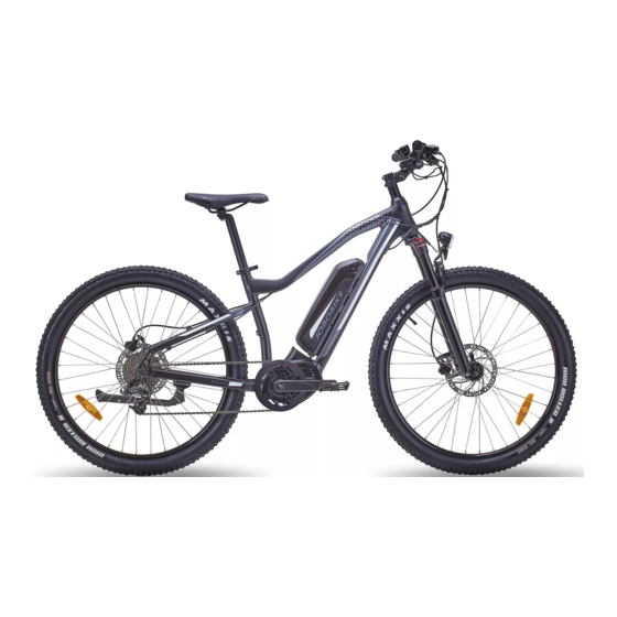
- Page 37 Tyre Inflation and Replacement BRUNO employs 27.5"X2.3" rubber tyres witch inner tubes. The tyres are designed for durability and safety during regular cycling activi - ties; they should be checked before each use for proper inflation and condition. Proper inflation, care, and timely replacement ensure that your bike’s operational characteristics are maintained, avoiding unwanted, unsafe situations.
-
Page 38: Tubleshooting
Tubleshooting Symptoms Possible Causes Most Common Solutions 1. Insufficient battery power 1. Charge the battery 2. Faulty connections 2. Clean and repair connectors The bike does not work 3. Battery not fully seated in tray 3. Install battery correctly 4. Improper turn on sequence 4. - Page 39 Error code Detection Your bike is equipped with an error detection system integrated into the display and controller. In the case of an elec- tronic control system fault, an error code should display. The following error codes are the most common and can aid troubleshooting. If your bike has an error code displayed at any time, it is recommended that you cease operation and contact JOBOBIKEs immediately.
- Page 40 1. Restart the system 2. Check that the magnet attached to the spoke is aligned with the speed sensor and that the distance is between 10 mm and 20 mm. 3. Check that the speed sensor connector is connect edcorrectly. Error with wheel speed detecting sensor 4.
-
Page 41: Warnings And Safety
1. Check if all connections on the pedelec are correctly connected. 2. Use the BESST Tool to run a diagnostics test, to see if it can pinpoint the problem. Communication problem 3. Change the display to see if the problem is solved. 4. - Page 42 • Ride predictably, in a straight line, and with the flow of traffic. Never ride against traffic. • Use correct hand signals to indicate turning. • Ride defensively because to other road users, you may be hard to see. • Concentrate on the path ahead.
- Page 43 • Ensure that the bike fits you properly before first use. You may lose control or fall if your bike is too big or too small. • Always wear an approved bicycle helmet when riding a bike and ensure that all instructions provided by the helmet manufacturer are used for fit and care of your helmet.
- Page 44 • Users must understand the operation of the twist power assist and pedal assistance sensors before using the bike and must travel at speeds appropriate for certain usage area, riding conditions, and user experience level. Always use the lowest assist level until you are com - fortable with the bike and feel confident in controlling the power.
-
Page 45: After Sales Policy
• In wet weather you need to take extra care when operating this bike. • Decrease riding speed to help you control the bike in slippery conditions. • Brake earlier since it will take brakes longer to slow down than when operated in dry conditions. •... - Page 46 Technical support If you have any technical problems with your e-bike, please fill out the contact form on our website www.jobobike.pl and specify the techni- cal issue. We will contact you regarding your issue with the bike as soon as possible. Should it be a small technical issue (such as changing parts in your bike) and you will be able to fix it yourself, we will send you replacement parts and assist you by phone or email.
- Page 47 Assembly instruction support You can find all our assembly instruction videos on official JOBOBIKE website as well as the official JOBOBIKE YouTube channel. If you have any more questions, please contact JOBOBIKE Technical Support Team at support@jobobike.pl or using contact form at www.jobobike.plThe guarantee can not be claimed if changes have been made to the original construction, if the wheel is not used as intended or if there is any other overuse.
Need help?
Do you have a question about the JOBOBIKE Bruno and is the answer not in the manual?
Questions and answers