
Related Manuals for LNS QUICK LOAD SERVO S3 T BARFEED


Summary of Contents for LNS QUICK LOAD SERVO S3 T BARFEED
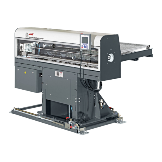
- Page 1 QUICK LOAD SERVO S3 T BARFEED Service Manual For CNC machine tool peripherals, it’s LNS , then all the rest 9.021.04.02.EN. US...
- Page 2 GENERAL SERVICE MANUAL – QL Servo S3-T...
- Page 3 GENERAL IMPORTANT READ THIS MANUAL CAREFULLY BEFORE USING AND RETAIN FOR FUTURE REFERENCE. Published: 08/2020 © LNS America 2020 – 9.021.04.01 EN (V00.0) – Service manual – Printed in LNS America SERVICE MANUAL – QL Servo S3-T...
-
Page 4: Table Of Contents
GENERAL TABLE OF CONTENTS GENERAL ..........................6 ABOUT THIS SERVICE MANUAL .................... 6 WHO IS THIS MANUAL FOR? ....................6 OTHER APPLICABLE DOCUMENTS ..................6 IN THE CASE OF DAMAGE CAUSED DURING TRANSPORTATION ........6 SYMBOLS AND WARNING LABELS ..................7 CONVENTIONAL TERMS AND SYMBOLS ................ - Page 5 GENERAL SETTINGS ..........................64 DESCRIPTION ........................64 ACCESS TO THE FUNCTIONS ..................... 65 END OF BAR POSITION ......................81 TOP-CUT POSITION ......................83 MAINTENANCE ........................86 INSPECTIONS ........................86 UPDATING THE PROGRAM ON A PLC ................87 CLEANING ..........................92 TECHNICAL CHARACTERISTICS ..................
- Page 6 GENERAL SERVICE MANUAL – QL Servo S3-T...
-
Page 7: General
LNS accepts no responsibility in case of deterioration or degradation of the products during their transportation. LNS will assert a claim for loss or damage to those carriers that have been arranged by LNS. If LNS does not make the freight arrangements, we are not responsible for the freight issues once the article has been loaded on the truck from our dock. -
Page 8: Symbols And Warning Labels
GENERAL SYMBOLS AND WARNING LABELS Warning labels and consequences in case of non-compliance with the safety instructions DANGER Type and origin of danger! Consequences of non-compliance with the warning. What to do to avoid danger. Warnings of imminent danger, which, if not avoided, may result in: serious or fatal injury WARNING Type and origin of danger! -
Page 9: Conventional Terms And Symbols
LNS. LNS and its subsidiaries will not be liable for damages and problems arising from the use of options and products other than those provided or approved by LNS. -
Page 10: Safety Instructions
• Always use the parts supplied or recommended by LNS for use/intervention on the bar feeder for maintenance purposes. If it is necessary to move the bar feeder after commissioning, always contact LNS or a local representative before • restarting the system. -
Page 11: Procedures
PROCEDURES 2. PROCEDURES SETUP, ALIGNMENT, AND ANCHOR PROCEDURE INFORMATION The following conditions must be met to complete this procedure: Bar feeder power off • No pneumatic pressure • Reminders: To obtain a perfect alignment, it is advisable to install the largest feeding pusher. •... - Page 12 PROCEDURES 2. Level the bar feed in the x and y axis using a torpedo level. The level can be placed on the linear belt rail to verify the y-axis and on the retract rails to verify the x-axis. Use the leveling screws (shown with arrows) on the retract to adjust unit to level.
- Page 13 PROCEDURES 4. Using the central jackscrew (1) and the hexagonal tube (2) supplied with the bar feed; adjust the unit so that the pusher is centered up and down at the back of the spindle. Make sure that the unit raises or lowers uniformly.
- Page 14 PROCEDURES 6. Align the unit side to side by centering the pusher in the back of the spindle and then extending the pusher to the back of the collet and centering it there. Adjust the rear of the bar feed when centering to the rear of the spindle and the front of the bar feed when centering to the rear of the collet.
- Page 15 PROCEDURES 8. After anchoring the unit, recheck the level and the alignment of the unit. 9. After the alignment has been rechecked, power and air will need to be hooked up to the bar feeder. 10. Once the power and air have been hooked up, the bar feed must be calibrated. After calibrating the bar feed, return to this procedure and move on to Step 11 for the final alignment.
-
Page 16: Pusher Changeover
PROCEDURES PUSHER CHANGEOVER INFORMATION The following conditions must be met to complete this procedure: • Bar feeder switch on Loading table in lower position • • Pusher at the mechanical home position Bar feed in STOP mode • 1. Open the main access cover. 2. - Page 17 PROCEDURES 5. Pull out the guide bushing from the front ring. 8. Push the guide bushing in the front ring. 6. Remove the pusher from the bar feed. 7. Put the new pusher in the bar feed. 9. Place the rear end of the pusher in the carrier 10.
-
Page 18: Servo Motor Belt Tension Adjustment
PROCEDURES SERVO MOTOR BELT TENSION ADJUSTMENT INFORMATION The following condition must be met to complete this procedure: • Bar feeder POWER OFF 2. Loosen the four nuts on the motor mount plate. 1. Open the main access cover. 3. Using a lever (ex. screwdriver), 4. -
Page 19: Carriage Unit Belt Tension Adjustment
PROCEDURES CARRIAGE UNIT BELT TENSION ADJUSTMENT INFORMATION The following conditions must be met to complete this procedure: • Bar feeder POWER on Bar feed in [STOP] mode • 2. Loosen the four nuts on the motor mount plate. 1. Open the main access cover. 3. -
Page 20: Diameter Adjustment Motor Replacement
PROCEDURES DIAMETER ADJUSTMENT MOTOR REPLACEMENT INFORMATION The following conditions must be met to complete this procedure: • Bar feeder POWER on Bar feed in [STOP] mode • 1. Remove the front panel on the sub-base . 2. Remove the two rear panels on the sub-base . 3. - Page 21 PROCEDURES 4. Remove the two screws holding on the 5. Disconnect the SQ4 cable from the mounted adjustment motor. proximity switch. 6. Disconnect the M2 cable from the XP1 7. Insert the new motor and connect the M2 connector and remove the bad motor . cable to the XP1 connector.
- Page 22 PROCEDURES 9. While pulling the motor toward the front of the bar feed to keep the chain taut, tighten the two screws for the motor assembly. 10. Reassemble the chain guard . 11. Reassemble the front and rear panels . SERVICE MANUAL –...
-
Page 23: Home Position Proximity Switch Adjustment - Sq5
PROCEDURES HOME POSITION PROXIMITY SWITCH ADJUSTMENT – SQ5 INFORMATION The following conditions must be met to complete this procedure: Bar feeder POWER on • Bar feed in [STOP] mode • Pusher at the mechanical home position against the reference plate •... -
Page 24: Measuring Cell Adjustment - Sq3
PROCEDURES MEASURING CELL ADJUSTMENT – SQ3 INFORMATION The following conditions must be met to complete this procedure: • Bar feeder POWER on Loading table in upper position. • Bar feed in [STOP] mode • 1. Retract the bar feed for access to the front of the unit . 2. - Page 25 PROCEDURES 5. Loosen screws and adjust the cell so that the “red” sensor is reflecting off the center of the bar and tighten the cell down . 6. Turn the gain adjustment CCW to the 7. From the minimum position slowly turn the minimum position .
-
Page 26: Pusher Reversing Distance Adjustment
PROCEDURES PUSHER REVERSING DISTANCE ADJUSTMENT The pusher reverses a specified distance, after the chuck closes, so that it is not making contact with the rotating bar or the spindle. Generally, the smaller the diameter of the pusher the greater the reversing distance. This is due to deflection (or sagging) of the pusher, which is caused when the pusher is far up in the spindle of the lathe and can no longer support its own weight so the tip of the pusher begins to sag. -
Page 27: Magazine And Loading Finger Adjustment
PROCEDURES MAGAZINE AND LOADING FINGER ADJUSTMENT The slope of the magazine rack needs to be adjusted when the shape of the material being loaded changes from round to profiled or visa versa. When loading round stock, if the slope of the magazine is too much it is possible for the material to stack up and cause double loading if the weight of the material is great enough (especially when loading smaller diameter stock). -
Page 28: Calibration Of The Loading Table
PROCEDURES CALIBRATION OF THE LOADING TABLE INFORMATION The following conditions must be met to complete this procedure: • Bars on the magazine. Loading table in lower position • Bar feed in [STOP] mode • Switch to manual mode by pressing the [F2] key. Bring the table to the raised position [F3]. -
Page 29: Finding Software/Plc Versions
PROCEDURES FINDING SOFTWARE/PLC VERSIONS INFORMATION The following condition must be met to complete this procedure: • Bar feeder POWER on In the working menu, press the [HELP] key on the remote control. SOFTWARE UPDATE INFORMATION The following condition must be met to complete this procedure: Bar feeder POWER on •... -
Page 30: Plc Battery Replacement
PROCEDURES PLC BATTERY REPLACEMENT INFORMATION The following condition must be met to complete this procedure: • Bar feeder POWER on In the electrical cabinet, open the PLC cover. Take the battery support out of the bay labeled "BATT". Replace the battery with an identical type. Check that the battery is in the right direction. Insert back the battery support in its bay. -
Page 31: Mechanical Equipment
MECHANICAL EQUIPMENT 3. MECHANICAL EQUIPMENT WARNING Moving parts pose a risk of injury! Crushing and cutting hazards. Always unplug the power plug and shut off the air supply before servicing the bar feeder. BAR MAGAZINE DESCRIPTION Placed on the side of the bar feeder, the bar magazine is 1000 mm deep and can house bars of different lengths, from 300 mm to 1600 mm. - Page 32 MECHANICAL EQUIPMENT LAYOUT OF THE ELEMENTS Designation Description Magazine table Protection grid for magazine table Rear limiter Loading table support Fingers for bar selection Holding rod SQ11 Grid closed safety switch SERVICE MANUAL – QL Servo S3-T...
- Page 33 INFORMATION The maximum length (L.max.) must be entered into the service parameters (only an LNS or approved technician is authorized to edit this value). SERVICE MANUAL – QL Servo S3-T...
- Page 34 Conversely, if bars with a small diameter start to pile up, the gradient can be decreased. PROFILED MATERIAL Depending on the profile of the bars to be loaded, additional settings and accessories are required. Please contact LNS or their local representative.
-
Page 35: Loading Table
MECHANICAL EQUIPMENT LOADING TABLE DESCRIPTION When they are on the magazine, the bars (A) press against the loading stops (B). The stops are arranged on an axis (C) which is coupled to the loading table (D). The stops are adjusted automatically by the electric motor M2, at the same time as the loading table is configured. -
Page 36: Pusher Carrier
The length of the pushers is fixed and does not depend on the spindle length. As a safety measure, the pushers are equipped with a mechanical stop. For loading of tubes, profiled bars or short bars, optional elements may be installed. Please contact your local LNS agent for more information. -
Page 37: Loading Pusher
MECHANICAL EQUIPMENT LOADING PUSHER Contrary to the feeding pusher, the loading pusher (2) does not need to be replaced when the bar diameter changes. Same-length bars may be loaded directly with a loading pusher without using the feeding pusher. To do this, a special extended loading pusher, available as an option, is required. - Page 38 MECHANICAL EQUIPMENT MECHANICAL STOP The bar feeder pusher has a fixed length, which was determined to ensure it is suited to all types of lathes. To guarantee that they never collide with the collet (for example: end of bar incorrectly set or in manual mode), the bar feeder pushers are equipped with a mechanical safety stop.
- Page 39 MECHANICAL EQUIPMENT 2. The second consists of replacing the pusher tip (C) with a special tip (D) with a diameter of 130 mm (available for the ø 25 mm pusher only). To enable it to penetrate the spindle (F), the tip must be turned at a diameter 4 millimeters less than the spindle passage (F).
-
Page 40: Retraction
MECHANICAL EQUIPMENT RETRACTION When a lathe is equipped with a bar feeder, certain elements (motors, spindle reduction tubes, etc.) become inaccessible, and sometimes it is difficult, or even impossible, to proceed with their maintenance. To facilitate these tasks, the bar feeder is equipped with a retraction system which allows the operator to move it. Designation Description Rails... -
Page 41: Kit For Quick Part Loading (Option)
MECHANICAL EQUIPMENT KIT FOR QUICK PART LOADING (OPTION) Parts of the same length may be loaded with a special pusher (A). The loading procedure is simplified, and the loading time can be reduced by adapting the interface with the lathe. This kit includes a specific pusher with a diameter of 12 mm, which can be adjusted to the length of the part to be loaded. - Page 42 MECHANICAL EQUIPMENT SERVICE MANUAL – QL Servo S3-T...
-
Page 43: Pneumatic Equipment
PNEUMATIC EQUIPMENT 4. PNEUMATIC EQUIPMENT INFORMATION To guarantee optimal operation of the bar feeder, a minimum pressure of 5 bar (75 psi/500 kPa) is mandatory. LAYOUT OF THE ELEMENTS Designation Description Air handling unit with pressure control unit Solenoid valve block Pneumatic cylinders for vertical movement of the table Pusher locking pneumatic cylinder SERVICE MANUAL –... -
Page 44: Air Treatment Unit
PNEUMATIC EQUIPMENT AIR TREATMENT UNIT LAYOUT OF THE ELEMENTS Designation Description Air inlet Pressure regulator Regulated air outlet (Ø 8 mm, G1/4 push-in fitting) Manometer Decanter Discharge screw ADJUSTING THE SERVICE PRESSURE 1) Unlock the adjusting knob by pulling it upward. 2) Turn the regulator until the pressure gauge indicates a correct value: 3) Reduce the pressure: Turn the regulator counter-clockwise Increase the pressure: Turn the regulator clockwise... -
Page 45: Pneumatic Battery
PNEUMATIC EQUIPMENT INFORMATION The operating pressure should be kept at 5 bar. PNEUMATIC BATTERY The pneumatic battery includes the control and monitoring elements of the bar feeder pneumatic circuit LAYOUT OF ELEMENTS Designation Description Solenoid Valve YV1A/YV1B Pressure switch SP1 Silencer SERVICE MANUAL –... - Page 46 PNEUMATIC EQUIPMENT SERVICE MANUAL – QL Servo S3-T...
-
Page 47: Electrical Equipment
Danger of death by electrocution! Only qualified electricians are authorized to intervene on the electric circuit. If there is a fault that you believe is electrical, contact LNS or a local representative. SAFETY COMPONENTS These components are installed to ensure safe use of the bar feeder. -
Page 48: Electrical Components
ELECTRICAL EQUIPMENT ELECTRICAL COMPONENTS Designation Description Remote control 24-pin interface plug with cover (depending on interface) Not Shown Electrical cabinet Main disconnect switch servomotor Motor for setting the diameter Control switch, table in lowered position Control switch, table in raised position Light sensor Proximity switch for setting the diameter (not visible) Original position carriage sensor... -
Page 49: Electrical Cabinet
ELECTRICAL EQUIPMENT ELECTRICAL CABINET LAYOUT OF THE ELEMENTS IN THE ELECTRICAL CABINET SERVICE MANUAL – QL Servo S3-T... - Page 50 ELECTRICAL EQUIPMENT Designation Description Input – output terminal blocks X1 (YV1 – YV8) Safety terminal blocks X3 (T1 – T6) PCD3 Programmable controller PCD3 (PLC) Servo amplifier 400W Diameter adaption motor fuse 2A Safety contactor Start relay K8-K9 Safety control module Safety contactor (option) Relay: Motor M2 “Up”...
- Page 51 ELECTRICAL EQUIPMENT TRANSFORMERS 230 V (T1) AND 24 VDC (T2) The transformers T1 and T2 power the entire low voltage network of the bar feed system, as well as a portion of the interface signals, The transformer T1 has an output of 230 Volts which powers the amplifier of the SERVO motor A fuse installed in a support protects the transformer T1 output.
-
Page 52: Remote Control
ELECTRICAL EQUIPMENT REMOTE CONTROL The remote control is used as: - A control element - A signal element The ergonomic and user-friendly remote control with a clear built-in display facilitates the handling of the bar feeder. Depending on the sequence under way, the bar feeder gives access only to those functions which are available, thus avoiding any incorrect handling, and reducing the access time to the necessary functions. - Page 53 ELECTRICAL EQUIPMENT INFORMATION Some software settings are protected by a password. Password-protected settings are used for basic machine configuration and should only be performed by qualified personnel. DISPLAY The liquid crystal display provides the operator with all the necessary data, both for handling the bar feed system and for maintenance.
- Page 54 ELECTRICAL EQUIPMENT The available icons are as follows: Icon Meaning Icon Meaning Referencing position Set current parameter Switch to automatic mode Exit the current function, back to start Stop after machining one bar Back to previous page Switch to manual mode Go to next page Pusher forward (picture may be Fit the loading table...
- Page 55 ELECTRICAL EQUIPMENT FUNCTION KEYS F1 - F4 The multi-function keys are located right below the display. The functions attributed to them are indicated on the display by icons. Left / right / up / down keys DIRECTION KEYS AND NUMBER KEY PAD These keys allow entering values (bar stock diameter, part length, etc.) or parameters.
-
Page 56: Servo Amplifier
ELECTRICAL EQUIPMENT SERVO AMPLIFIER The Servo amplifier controls the servomotor(s) of the bar feeder. The amplifier records the absolute position data. Thanks to a battery (1), this data is saved, and the axes do not need to be placed at zero for the powering on of the bar feeder. INFO The life of a battery can be 2-3 years. - Page 57 ELECTRICAL EQUIPMENT CAUTION Harmful to the environment! Do not dispose of used batteries in the environment. Bring the batteries to a recycling center. Otherwise, have it recycled by an authorized local service. To replace the battery: 1) Gently press the locking clip (2) 2) Open the battery compartment by removing the cover (1) 3) Remove the battery (3) from its housing and replace it 4) Refit the cover (1)
-
Page 58: Programmable Logic Controller
Cover Battery module M2 Slot for software update card. (Do not remove the flash card unless instructed by LNS. M1 Slot for memory expansion (Used to store parts library files. To replace the battery: 1) Lift the cover (2) by tilting it backward. -
Page 59: Accessory Components
ELECTRICAL EQUIPMENT ACCESSORY COMPONENTS These components carry out the instructions that are given by the control components (motors, hydraulic pump, etc.). SERVO MOTOR The Servo motor controls the drive of the notched belt FINGER ADJUSTMENT MOTOR The finger adjustment motor positions the fingers to the correct position to hold back the bars in the magazine. SENSORS The sensors can be identified by the signaling plates (1). -
Page 60: Identification Markings - Type Of Material
ELECTRICAL EQUIPMENT IDENTIFICATION MARKINGS – TYPE OF MATERIAL Letter Type of material Examples Identification Marking Relay Instant all-or-nothing relay Contactors Contactor Motors Mechanical Circuit breaker connection Motor protection switch devices for power circuits Sectioning device Connection Selector or switch devices for line Pressure sensor circuits (drive, control, signaling... -
Page 61: Connections
The LNS bar feed systems are equipped with their own thermal protection systems (breakers, thermal relays and fuses, etc.). The power supply for the bar feed system should be connected to the output of a breaker mounted in the electrical control box of the lathe (10 A max.). - Page 62 ELECTRICAL EQUIPMENT INFO As long as this signal is present, the signal of the foot switch to open and close the clamping device of the lathe must be locked. The lathe should not start up in automatic cycle as long as the clamping device does not grip the bar.
- Page 63 ELECTRICAL EQUIPMENT OPTIONS The options described below are an integral part of the standard equipment of the LNS bar feed systems. These signals, however, are not required for the proper operation of the devices, or the safety locking for protecting persons and materials.
- Page 64 ELECTRICAL EQUIPMENT SERVICE MANUAL – QL Servo S3-T...
-
Page 65: Settings
SETTINGS 6. SETTINGS This chapter indicates the activating and setting procedures for these functions. DESCRIPTION The bar feeder has several parameters and functions allowing the operator to configure it so that it adapts as closely as possible to the lathe on which it is installed, as well as to the production mode being employed. Thanks to these parameters, when feeding, the material can be positioned in the lathe's clamping unit. -
Page 66: Access To The Functions
SETTINGS ACCESS TO THE FUNCTIONS By pressing the MENU key, it is possible to access the setting functions. INFORMATION To modify these parameters, the bar feed must be in STOP mode. To validate some values or parameters, hold the [ENTER] key until the icon disappears. - Page 67 SETTINGS PART SETUP Form and diameter of the bar, length of part, face-off variable distance Material shape Round bar: • Outside diameter Hexagonal / square bar: • Size on flat sides • Size on corners During the bar feed cycle, the bar feeder tries several times (during 2 minutes) to insert the bar in the lathe collet or chuck.
- Page 68 SETTINGS Top-cut position(may not be visible) During feeding, the bar is inserted in the spindle and automatically positioned in the clamping unit of the lathe. This positioning corresponds to a value (Z) programmed by the operator, which is equal to the distance between the measuring cell and the position of the material in the lathe clamping device.
- Page 69 SETTINGS End of bar position (may be not visible) The end of bar position determines the moment when the bar feeder enters the loading cycle. In principle, the end of bar position is adjusted as closely as possible behind the lathe's clamping unit (approximately 5 mm) to ensure the shortest remnants.
- Page 70 This parameter must only be used when a physical limiter is in place on the bar magazine to prevent longer bars from being loaded, which could damage the lathe. Please contact your LNS agent for more information on this application.
- Page 71 SETTINGS Part feed out rate (may not be visible) This parameter is used to adapt the feed rate to the weight of the bar, for example when feeding out aluminum bars. APPLICATION SETUP Part feed out with/without turret Part feed out with turret This parameter determines whether the lathe controls the part feeding.
- Page 72 The end of bar position does not require any particular setting for this type of work. Contact your LNS agent for more information on this application. Misc. Applications Auto cycle simulation function - Dry Run (may not be visible) This function allows the lathe to be used (in a production cycle) without the bar feeder (piece work, lathe preheating, etc.).
- Page 73 SETTINGS POSITION End of bar position (may be not visible) The end of bar position determines the moment when the bar feeder enters the loading cycle. In principle, the end of bar position is adjusted as closely as possible behind the lathe's clamping unit (approximately 5 mm) to ensure the shortest remnants.
- Page 74 SETTINGS Auxiliary end of bar position (may be not visible) Depending on the lathe and its options, the auxiliary end of bar may be used in several ways. For example, for the opening of an additional front rest installed at the rear of the lathe spindle. The procedure is the same as this for the end of bar signal. TORQUES Torque set according to the diameter for part feed out (%) Depending on the bar diameter, the feeder suggests a suitable thrust torque.
- Page 75 PARTS LIBRARY NFORMATION The parts library is only operational if an optional memory extension card is installed on the PLC. Please contact LNS for more information. PART LIBRARY The main parts library screen shows the current state of the library.
- Page 76 SETTINGS LOAD PART This screen allows the parameters for an existing part to be recalled from the parts library and loaded into the parts parameters, by indicating its part ID. • Active part: shows the part currently loaded. Total parts: shows the total number of parts stored in the •...
- Page 77 Therefore, these parameters are protected with a password, and only an LNS (or certified) technician is authorized to modify them 1. Bar feeder Bar feeder location (left hand / right hand) Unit (mm/inch) Time for clamping device to close (factory value 0.0 sec)
- Page 78 SETTINGS 6. Working Bar feeder in : Working mode (normal operation) mode setup Simulation Demo mode Interface simulation with lathe, without bar 7. Display Parameter access: Sub spindle (no/yes) Parameter access: Quick part loading (no/yes) Parameter access: Loading with non-rotating reduction (no/yes) Parameter access: Mechanical stop (no/yes) Parameter access: Dry run function (no/yes) Parameter access: Loading with turret (no/yes)
- Page 79 SETTINGS HELP SCREENS From any screen in manual or automatic mode, press the HELP or “?” button on the screen, displays the help screens to troubleshoot or gather information about the software and components. 1. Software This screen displays the current software running the bar feeder and its version. 2.
- Page 80 SETTINGS 3. Inputs This screen shows the current input signals being used in the barfeed. 4. Outputs This screen shows the current output signals being used in the barfeed. SERVICE MANUAL – QL Servo S3-T...
- Page 81 SETTINGS 5. Alarms list This screen shows the history of the last 10 alarms. 6. Memory list This screen helps entering and monitoring specific bits (status in green/red), and register values (value in left box). SERVICE MANUAL – QL Servo S3-T...
-
Page 82: End Of Bar Position
SETTINGS END OF BAR POSITION DESCRIPTION The end of bar position determines the moment when the bar feed enters the loading cycle. Usually, the end of bar position is adjusted as closely as possible behind the clamping system of the lathe (approximately 5 mm or a 1/4" behind the chuck jaws or collet pads). - Page 83 SETTINGS SETTING Before handling the bar feeder, stop the lathe at the end of part cycle ! NFORMATION To edit these parameters, the bar feeder must be in STOP mode. To validate a new parameter or a new value, keep [ENTER] pressed until the icon disappears.
-
Page 84: Top-Cut Position
SETTINGS [+/-] by offset correction: • Press the key corresponding to the icon [+/-]. • The display shows the current end of bar position. [+/-] • Select the field named "Enter the new value", enter the correction to be considered and confirm with ok. •... - Page 85 SETTINGS SETTING NFORMATION Before handling the bar feeder, stop the lathe at the end of part cycle ! To edit these parameters, the bar feeder must be in STOP mode. To validate a new parameter or a new value, keep [ENTER] pressed until the icon disappears Press the key [STOP].
- Page 86 SETTINGS [+/-] [+/-] by offset correction: • Press the key corresponding to the icon [+/-]. • The current top-cut position (z) is displayed. • Select the field named "Enter the new value", enter the correction to be considered and confirm with ok. •...
-
Page 87: Maintenance
Electrical hazard! Danger of death by electrocution! Only qualified electricians are authorized to intervene on the electric circuit. If there is a fault that you believe is electrical, contact LNS or a local representative. WARNING Moving parts pose a risk of injury! Crushing and cutting hazards. -
Page 88: Updating The Program On A Plc
MAINTENANCE UPDATING THE PROGRAM ON A PLC 1) Release the bar feeder: Turn the switch (1) in a counterclockwise direction, to O (off) position 2) Remove the memory module from the slot for software update card (2) 3) Remove the micro SD card (4) from the memory module (3) SERVICE MANUAL –... - Page 89 MAINTENANCE 4) Insert the micro SD card (2) into the adapter (1) 5) Insert the adapter into the PC 6) Open the "SBC SD FLASH EXPLORER" software 7) Select File/Open SERVICE MANUAL – QL Servo S3-T...
- Page 90 MAINTENANCE 8) The following screen is displayed Select the file SAIANTFS.FFS on the card 9) The following screen is displayed 10) Select File/Restore 11) Select the file XXXXXXXXS.BACKUP SERVICE MANUAL – QL Servo S3-T...
- Page 91 MAINTENANCE 12) Wait for the restoration of the files to be complete 13) Select File/Save 14) Close the "SBC SD FLASH EXPLORER" software 15) Eject the PC adapter using the Windows Explorer function SERVICE MANUAL – QL Servo S3-T...
- Page 92 MAINTENANCE 16) Remove the micro SD card (2) from the adapter (1) 17) Insert the micro SD card (4) into the memory module (3) 18) Insert the memory module (3) into the slot for software update card (5) SERVICE MANUAL – QL Servo S3-T...
-
Page 93: Cleaning
MAINTENANCE 19) Engage the bar feeder: Turn the switch (1) in a clockwise direction, to I (on) position 20) Wait until the PLC is in RUN mode 21) Press the RUN/HALT button (approx. 3 seconds) until the LED RUN/HALT (2) of the battery module flash CLEANING By regularly cleaning your bar feeder, you will be able to optimize its operation and extend its life. - Page 94 MAINTENANCE NOTICE Risk of damage to the machine! It is strongly discouraged to clean the machine with compressed air. Particles may remain blocked in sensitive areas and thus compromise the proper functioning of the bar feeder. NOTICE Solvent-based cleaning products damage the finishing paint! Never clean the bar feeder with solvents, such as acetone, or thinners.
-
Page 95: Technical Characteristics
TECHNICAL CHARACTERISTICS 8. TECHNICAL CHARACTERISTICS Weight 1260 lbs 570 kg Overall length 80.6 in 2048 mm Overall width 58.5 in 1486 mm Depth of the bar magazine 39.4 in 1000 mm Height 49.1 – 68.8 in 1248 - 1748 mm 900 - 1200 mm / 1200 - Axis height 35.1 –... - Page 96 TECHNICAL CHARACTERISTICS SERVICE MANUAL – QL Servo S3-T...
-
Page 97: Disposal
DISPOSAL 9. DISPOSAL MACHINE At the end of its service life, the machine will be permanently decommissioned and deposited at a recycling collection point. CAUTION Harmful to the environment! Improper disposal of the machine can cause serious harm to the environment. - Page 98 DISPOSAL SERVICE MANUAL – QL Servo S3-T...
-
Page 99: Troubleshooting
TROUBLESHOOTING 10. TROUBLESHOOTING Errors detected by the PLC will be displayed on the HMI screen. ALARMS Text alarm Description Solutions Safety Line open! The lathe or the bar feeder goes Check the states of the emergency stop buttons of into emergency stop barfeed and lathe. - Page 100 TROUBLESHOOTING Text alarm Description Solutions Failure on switch The PLC does not detect input Check the switch SQ2. SQ2 ! (I9 – SQ2). Failure while mechanical obstruction Check that there is no mechanical obstruction loading table prevented the table from moving moving up ! Check switches SQ1 and SQ2.
- Page 101 Check the lathe program. begin not in sync ! openings do not match. Check the quantity of chuck openings per part. Default on An error has happened on the Contact your LNS agent. telescopic pusher telescopic pusher system. system ! Servo positioning There...
- Page 102 Do not shut down the barfeeder until the battery has been replaced. Amplifier firmware The firmware of the servo drive The amplifier must be replaced. Please contact your not compatible ! is not compatible with the LNS LNS agent. software. SERVICE MANUAL – QL Servo S3-T...
-
Page 103: Sequence Diagram
TROUBLESHOOTING SEQUENCE DIAGRAM SERVICE MANUAL – QL Servo S3-T... -
Page 104: Sequence Listing
TROUBLESHOOTING SEQUENCE LISTING SERVICE MANUAL – QL Servo S3-T... - Page 105 TROUBLESHOOTING SERVICE MANUAL – QL Servo S3-T...
-
Page 106: Mitsubishi Alarm List Mrj-4
TROUBLESHOOTING MITSUBISHI ALARM LIST MRJ-4 Alarm code Alarm deactivation Stop Detail Name Detail Name System number (Note 2,3) (Bit 2) (Bit 1) (Bit 0) ���� ���� Voltage drop in the control circuit ���� 10.1 power ���� ���� ���� Undervoltage Voltage drop in the main circuit 10.2 power ����... - Page 107 TROUBLESHOOTING Alarm code Alarm deactivation Stop Detail Name Detail Name System number (Note 2,3) (Bit 2) (Bit 1) (Bit 0) Absolute position Servo motor encoder - Absolute ���� 25.1 erased position erased ���� ���� ���� Initial magnetic pole detection 27.1 Abnormal termination ����...
- Page 108 TROUBLESHOOTING Alarm code Alarm deactivation Stop Detail Name Detail Name System number (Note 2,3) (Bit 2) (Bit 1) (Bit 0) ���� ���� ���� Thermal overload error during 50.1 operation (Note (Note (Note ���� ���� ���� Thermal overload error during 50.2 operation (Note (Note...
- Page 109 TROUBLESHOOTING Alarm code Alarm deactivation Stop Detail Name Detail Name System number (Note 2,3) (Bit 2) (Bit 1) (Bit 0) ���� Load-side encoder data error 72.1 ���� Load-side encoder data update 72.2 error ���� Load-side encoder data waveform Load-side encoder 72.3 error normal...
-
Page 110: Mitsubishi Warning List Mrj-4
TROUBLESHOOTING MITSUBISHI WARNING LIST MRJ-4 Name Detail number Detail Name Stop System (Note 2,3) Servo amplifier overheat warning (Note 91.1 Main circuit device overheat warning Encoder battery cable disconnection Battery cable disconnection warning 92.1 warning 92.3 Battery degradation data transfer requirement warning ABS data transfer... -
Page 111: Mitsubishi Alarms Cause And Solutions
TROUBLESHOOTING MITSUBISHI ALARMS CAUSE AND SOLUTIONS Display Error name Definition Cause Action AL.10 Undervoltage Power supply 1. Power supply voltage is low Review the power supply voltage dropped. 2. There was an instantaneous MR J2S-CP:160V control power failure of 60 ms or or less longer MR J2S-CP1:83V... - Page 112 TROUBLESHOOTING Display Error name Definition Cause Action Power was 4. Super capacitor of the After leaving the alarm switched on for the absolute position encoder is not occurring for a few first time in the charged minutes, switch power absolute position off, then on again.
- Page 113 TROUBLESHOOTING Display Error name Definition Cause Action 4. External noise caused the Take noise suppression overcurrent detection circuit to measures. misoperate. AL.33 Overvoltage Converter bus 1. Lead of built-in regenerative 1. Change lead. voltage exceeded brake resistor or regenerative 2. Connect correctly. 400V.
- Page 114 TROUBLESHOOTING Display Error name Definition Cause Action Load ratio 300%: 2. Servo system is instable and 1. Repeat acceleration/ 2.5s or more hunting. deceleration to execute auto tuning. Load ratio 200%: 2. Change auto tuning 100s or more response setting. 3.
- Page 115 TROUBLESHOOTING Display Error name Definition Cause Action 3. Motor cannot be started due to 1. Review the power torque shortage caused by power supply capacity. supply voltage drop. 2. Use servo motor which provides larger output. 4. Position control gain 1 Increase set value and (parameter No.7) value is small.
- Page 116 TROUBLESHOOTING Display Error name Definition Cause Action AL.96 Home position Home position 1. Droop pulses remaining are Remove the cause of setting warning setting could not be greater than the in-position range droop pulse occurrence made. setting 2. Command pulse entered after Do not enter command clearing of droop pulses.
-
Page 117: Plc Inputs/Outputs
TROUBLESHOOTING PLC INPUTS/OUTPUTS Inputs Outputs Input Des. Description Output Des. Description Safety line switch YV1A Working position valve Air pressure control unit YV1B Loading position valve SQ10 Protection cover safety switch Motor M2 raised relay (up) SQ11 Safety switch (grid protection) Motor M2 raised relay (down) SQ12 Retraction system safety device... -
Page 118: Product Manuals
TROUBLESHOOTING PRODUCT MANUALS To access product information via the QR code at right, a scanner will need to be downloaded to your smartphone. There are many “free” scanners available for all types of smartphones. Upon downloading a scanner to your smartphone, you can scan the QR code. To easily download information from the QR code, it’s recommended you have DropBox downloaded to your smartphone. - Page 119 TROUBLESHOOTING HOW TO ACCESS PRODUCT INFORMATION FOR DIRECT DOWNLOAD STEP 1 STEP 2 Point your smartphone at Upon the QR code to downloading be recognized. “Scanner App”, open the app. When message “Launch website” appears, select “Go” STEP 3 STEP 4 When Select the arrow “Go”, you will see...
-
Page 120: After-Sales Service
TROUBLESHOOTING AFTER-SALES SERVICE Customer Service (Service): BFsupport@LNS-northamerica.com Customer Service (Parts): BFparts@LNS-northamerica.com Phone: 513-528-5674 Fax : 513-528-5733 SERVICE MANUAL – QL Servo S3-T... -
Page 121: Appendices
APPENDICES 11. APPENDICES GLOSSARY Bearing Machine component in which a shaft or other elements turn Motor Equipment transforming electrical energy into mechanical energy Programmable Logic Controller: Digital computer used for process automation. The PLC controls the machine’s operation. Shaft Steel bar for supporting rotating elements or to transfer power SD card Removable memory card (Secure Digital) Informed persons... -
Page 122: Wiring Diagram 021-40-620F Ce Mrj-4
APPENDICES WIRING DIAGRAM 021-40-620F CE MRJ-4 SERVICE MANUAL – QL Servo S3-T... - Page 123 APPENDICES SERVICE MANUAL – QL Servo S3-T...
- Page 124 APPENDICES SERVICE MANUAL – QL Servo S3-T...
- Page 125 APPENDICES SERVICE MANUAL – QL Servo S3-T...
- Page 126 APPENDICES SERVICE MANUAL – QL Servo S3-T...
- Page 127 APPENDICES SERVICE MANUAL – QL Servo S3-T...
- Page 128 APPENDICES SERVICE MANUAL – QL Servo S3-T...
- Page 129 APPENDICES SERVICE MANUAL – QL Servo S3-T...
- Page 130 APPENDICES SERVICE MANUAL – QL Servo S3-T...
- Page 131 APPENDICES SERVICE MANUAL – QL Servo S3-T...
-
Page 132: Wiring Diagram 021-40-650F Ce Dcs Mrj4
APPENDICES WIRING DIAGRAM 021-40-650F CE DCS MRJ4 SERVICE MANUAL – QL Servo S3-T... - Page 133 APPENDICES SERVICE MANUAL – QL Servo S3-T...
- Page 134 APPENDICES SERVICE MANUAL – QL Servo S3-T...
- Page 135 APPENDICES SERVICE MANUAL – QL Servo S3-T...
- Page 136 APPENDICES SERVICE MANUAL – QL Servo S3-T...
- Page 137 APPENDICES SERVICE MANUAL – QL Servo S3-T...
- Page 138 APPENDICES SERVICE MANUAL – QL Servo S3-T...
- Page 139 APPENDICES SERVICE MANUAL – QL Servo S3-T...
- Page 140 APPENDICES SERVICE MANUAL – QL Servo S3-T...
- Page 141 APPENDICES SERVICE MANUAL – QL Servo S3-T...
- Page 142 APPENDICES SERVICE MANUAL – QL Servo S3-T...
-
Page 143: Wiring Diagram 021-40-622C Ce Mrj4 Qlsiii Mi
APPENDICES WIRING DIAGRAM 021-40-622C CE MRJ4 QLSIII MI SERVICE MANUAL – QL Servo S3-T... - Page 144 APPENDICES SERVICE MANUAL – QL Servo S3-T...
- Page 145 APPENDICES SERVICE MANUAL – QL Servo S3-T...
- Page 146 APPENDICES SERVICE MANUAL – QL Servo S3-T...
- Page 147 APPENDICES SERVICE MANUAL – QL Servo S3-T...
- Page 148 APPENDICES SERVICE MANUAL – QL Servo S3-T...
- Page 149 APPENDICES SERVICE MANUAL – QL Servo S3-T...
- Page 150 APPENDICES SERVICE MANUAL – QL Servo S3-T...
-
Page 151: Pneumatic Diagram
APPENDICES PNEUMATIC DIAGRAM SERVICE MANUAL – QL Servo S3-T... -
Page 152: Order Form
APPENDICES ORDER FORM You may photocopy this form, fill it out in its entirety and send it back to your nearest LNS reseller or retailer. Company name: Person in charge: Address: ZIP: City: Country: Phone: Fax: Type of device: Serial number: Qty.
Need help?
Do you have a question about the QUICK LOAD SERVO S3 T BARFEED and is the answer not in the manual?
Questions and answers