
Related Manuals for LNS ALPHA SL65 S


Summary of Contents for LNS ALPHA SL65 S
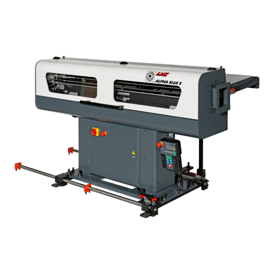
- Page 1 ALPHA SL65 S BARFEED Service Manual For CNC machine tool peripherals, it’s LNS , then all the rest 9.222.01.01.EN.US...
- Page 2 GENERAL IMPORTANT READ THIS MANUAL CAREFULLY BEFORE USING AND RETAIN FOR FUTURE REFERENCE. Published: 08/2020 © LNS America 2020 – 9.222.01.01 EN (V00.0) – Service manual – Printed in LNS America SERVICE MANUAL –ALPHA SL 65S...
-
Page 3: Table Of Contents
GENERAL TABLE OF CONTENTS GENERAL ..........................6 ABOUT THIS SERVICE MANUAL .................... 6 WHO IS THIS MANUAL FOR? ....................6 OTHER APPLICABLE DOCUMENTS ..................6 IN THE CASE OF DAMAGE CAUSED DURING TRANSPORTATION ........6 SYMBOLS AND WARNING LABELS ..................7 CONVENTIONAL TERMS AND SYMBOLS ................ - Page 4 GENERAL ANALOG MODULE ......................... 52 PROGRAMMABLE LOGIC CONTROLLER ................53 PCB (PRINTED CIRCUIT BOARD) ..................54 ACCESSORY COMPONENTS ....................55 CONNECTIONS ........................56 SETTINGS ..........................60 OPERATION PARAMETERS ....................60 DESCRIPTION ........................62 SERVICE PARAMETERS ...................... 70 ACCESSING ........................... 70 QUICK PREVIEW ........................
- Page 5 GENERAL SERVICE MANUAL – ALPHA SL 65S...
-
Page 6: General
LNS accepts no responsibility in case of deterioration or degradation of the products during their transportation. LNS will assert a claim for loss or damage to those carriers that have been arranged by LNS. If LNS does not make the freight arrangements, we are not responsible for the freight issues once the article has been loaded on the truck from our dock. -
Page 7: Symbols And Warning Labels
GENERAL SYMBOLS AND WARNING LABELS Warning labels and consequences in case of non-compliance with the safety instructions DANGER Type and origin of danger! Consequences of non-compliance with the warning. What to do to avoid danger. Warnings of imminent danger, which, if not avoided, may result in: serious or fatal injury WARNING Type and origin of danger! -
Page 8: Conventional Terms And Symbols
LNS. LNS and its subsidiaries will not be liable for damages and problems arising from the use of options and products other than those provided or approved by LNS. -
Page 9: Safety Instructions
Always use the parts supplied or recommended by LNS for use/intervention on the bar feeder for maintenance purposes. • If it is necessary to move the bar feeder after commissioning, always contact LNS or a local representative before restarting the system. -
Page 10: Procedures
PROCEDURES 2. PROCEDURES LIFTING THE BARFEED INFORMATION For installing the bar feeder, it’s advisable to contact us or one of our branches, agents. We cannot be held responsible for any malfunction resulting from an incorrect installation in which we did not take part in. 1. -
Page 11: Mounting Of X-Axis Retraction System
PROCEDURES MOUNTING OF X-AXIS RETRACTION SYSTEM INFORMATION The magazine slides with the bar feeder when the retraction is used. Before mounting the system, make sure the floor surface is flat and smooth.. The retraction system allows the bar feeder moving on certain distance so that there is some space behind the spindle for service. -
Page 12: Mounting Of Z-Axis Retraction System
PROCEDURES MOUNTING OF Z-AXIS RETRACTION SYSTEM INFORMATION The magazine slides with the bar feeder when the retraction is used. Before mounting the system, make sure the floor surface is flat and smooth.. The Z-axis retraction system allows the bar feeder moves among the longitudinal direction. This movement gives more space on the lateral direction. -
Page 13: Positioning
PROCEDURES POSITIONING The bar feeder must be placed behind the lathe as closer as it could be. The maximum distance between the lathe and bar feeder should not exceed 20mm (A) dimension. In the other words, the bar stock length should not exceed spindle length. BAR FEEDER WITHOUT RETRACTION SYSTEM BAR FEEDER WITH RETRACTION SYSTEM If the bar feeder is equipped with retraction system, please position the bar feeder after the retraction is locked on the bar... -
Page 14: Leveling
PROCEDURES LEVELING INFORMATION Before preceding this step, make sure that the lathe is leveled. BAR FEEDER WITHOUT RETRACTION SYSTEM Put the level gauge on the bar feeder stand. Loose 8 nuts (A) on the stand. Level the bar feeder by adjusting 8 screws (B). Turn the bolt clockwise until it touches against the ground and to lift the bar feeder or turn it counter-clockwise to lower the bar feeder. - Page 15 PROCEDURES BAR FEEDER WITH X-AXIS RETRACTION SYSTEM Verify that nuts (A) are locked to fixed stand. Put the level gauge on the bar feeder stand. Loose nuts (B) on the stand bottom plate. Turn screws (C) clockwise to lift / counter-clockwise to lower bar feeder for leveling. Lock all nuts (B) after the leveling is finished.
- Page 16 PROCEDURES BAR FEEDER WITH Z-AXIS RETRACTION SYSTEM Verify that nuts (A) are locked to fixed stand. Put the level gauge on the bar feeder stand. Loose nuts (B) on the stand bottom plate. Turn screws (C) clockwise to lift / counter-clockwise to lower bar feeder for leveling. Lock all nuts (B) after the leveling is finished.
-
Page 17: Alignment
PROCEDURES ALIGNMENT Open both stand covers. Make sure that nut B is contacting plate C Open the electrical cabinet. Loose nuts A on both sides (total 6 nuts). Adjust the bar feeder height by turning nuts B on each stand. Note that nut D must be always locked and should not be adjusted. -
Page 18: Center Adjustment
PROCEDURES CENTER ADJUSTMENT Designation Description Spindle Chuck Pusher Spindle rear end Spindle front end 1. Pusher and bar should be fed into the center of lathe spindle. 2. Move forward pusher out of bar feeder, check its center and lathe spindle center carefully and then adjust bar feeder position until pusher center matches spindle center perfectly. -
Page 19: Mounting The Magazine
PROCEDURES MOUNTING THE MAGAZINE The magazine is delivered in a folded down position. The user has to prepare it on the bar feeder before installation. Please follow the procedures below to install the magazine according to your bar feeder type. BAR FEEDER WITHOUT RETRACTION SYSTEM Unlock the magazine brackets by loosing screws pointed. - Page 20 PROCEDURES Mount the magazine stands. Loose nut C. Tilt the magazine by adjusting nut D. Lock nut C after the adjustment is finished. Lock the magazine brackets by tightening screws pointed. SERVICE MANUAL –ALPHA SL 65S...
- Page 21 PROCEDURES BAR FEEDER WITH X-AXIS RETRACTION SYSTEM 1. Unlock the magazine brackets by loosing screws pointed. Raise the brackets and then lock screws back. SERVICE MANUAL – ALPHA SL 65S...
- Page 22 PROCEDURES Mount the magazine base as shown. Mount the magazine stands. Loose nut C. Tilt the magazine by adjusting nut D. Lock nut C after the adjustment is finished. Adjust nut E so that the plates F are parallel with the bar feeder stand plates. Adjust nut G so that the magazine basement wheels J are able to contact with the ground.
-
Page 23: Anchoring
PROCEDURES ANCHORING After the bar feeder is positioned, leveled, aligned and the magazine is mounted. The bar feeder must be anchored. Figures below offer the anchoring location for each model. Please refer to corresponding instruction and anchor your bar feeder accordingly. -
Page 24: Pusher Changeover
PROCEDURES PUSHER CHANGEOVER Designation Description Locking Mechanism Pusher Lock Pin 1. Move the channel to lower position ( 2. Move the pusher to middle of the channel ( 3. Remove the lock pin. (3) Take out the locking mechanism (1) and the pusher (2) from the pusher assembly 4. -
Page 25: Setting Automatic/Manual Sequence
PROCEDURES SETTING AUTOMATIC/MANUAL SEQUENCE TURN THE CHANNEL TO 15° IN MANUAL MODE INFORMATION The following conditions must be met to complete this procedure: • The lathe is not in AUTOMATIC mode. • Channel at 0° position (SQ5 ON). • No material inside lathe spindle. Steps to lower the channel to 15°: 1. - Page 26 PROCEDURES 2. Press by sequence to switch the bar feeder to AUTOMATIC mode. 3. Switch the lathe to auto mode. WARNING Never switch the bar feeder into AUTOMATIC mode when the chuck is open!!! Never switch the lathe to AUTOMATIC mode before switching the bar feeder to AUTOMATIC mode.
-
Page 27: Bar Feeder In Automatic Mode
PROCEDURES 11. Press button until the long pusher pushes the bar stock against the stopper. 12. Close lathe chuck. 13. Switch the bar feeder to AUTOMATIC mode by pressing by sequence. The related LED will ON. The pusher will return back according to P04 or P02 setup. 14. -
Page 28: Switch The Bar Feeder Into Manual Sequence
PROCEDURES 35. Initiates TOP CUT. 36. Proceed step 17. SWITCH THE BAR FEEDER INTO MANUAL SEQUENCE INFORMATION The following conditions must be met to complete this procedure: • Lathe finishes a machining cycle and currently interrupts. • Lathe chuck is close Steps to switch the bar feeder into manual mode: 1. - Page 29 PROCEDURES SERVICE MANUAL – ALPHA SL 65S...
-
Page 30: Mechanical Equipment
MECHANICAL EQUIPMENT 3. MECHANICAL EQUIPMENT WARNING Moving parts pose a risk of injury! Crushing and cutting hazards. Always unplug the power plug and shut off the air supply before servicing the bar feeder. LOADING SYSTEM DESCRIPTION The loading system consists of bar magazine, loading fingers, stopping fingers and the loading cylinders. This system serves to storage and load bar stocks into the guiding channel. -
Page 31: Feeding System
MECHANICAL EQUIPMENT FEEDING SYSTEM DESCRIPTION The feeding system consists of the pusher assembly, transmission device and TOP CUT measuring switch. With this system, the servo motor drives the pusher forward and backward hence accomplish bar stock feeding. LAYOUT OF THE ELEMENTS Designation Description Pusher carrier... -
Page 32: Transmission
MECHANICAL EQUIPMENT TRANSMISSION DESCRIPTION Transmission unit consists of servo motor and pulley mounting/adjustment set. The pusher carrier is driven by servo motor. Without mechanical connection between the pusher and bar stock, it should keep some distance between pusher and rotating bar stock. -
Page 33: Pusher
MECHANICAL EQUIPMENT PUSHER DESCRIPTION The pusher assembly is composed of short and long pusher. Item Function Note Short pusher First feed The movement inside bar feeder TOP CUT Long pusher Feeding during production The movement outside bar feeder Remnant ejection There are 3 different diameters of pusher available for the bar feeder as shown below. -
Page 34: Channel Set
MECHANICAL EQUIPMENT V CHANNEL SET DESCRIPTION V channel set serves to support the bar stock during loading and FIRST FEED. The V channel has 2 operating positions. Only specific operation could be operated at each position. LOWER V CHANNEL This position serves to push the bar stock forward to the lathe (i.e. inside the lathe spindle) by moving long pusher forward. - Page 35 MECHANICAL EQUIPMENT HEIGHT ADJUSTMENT The channel upper position must be adjusted according to bar stock diameter. The bar stock is positioned at the feeding center when the channel is at upper position (around 0°). Follow the procedures below to adjust the channel upper position: Loose 2 locking handles as shown in counter-clockwise rotation Adjust the knob according to bar stock diameter.
-
Page 36: Spindle Liner
MECHANICAL EQUIPMENT SPINDLE LINER The spindle liner acts as an extension of guiding system. It fills the gap between the pusher/bar stock and spindle inner surface hence constrict the space of vibration. The spindle liner serves to support the pusher and bar stock inside the spindle when the spindle inner diameter is larger than the barstock. - Page 37 MECHANICAL EQUIPMENT SERVICE MANUAL – ALPHA SL 65S...
-
Page 38: Pneumatic Equipment
PNEUMATIC EQUIPMENT 4. PNEUMATIC EQUIPMENT INFORMATION To guarantee optimal operation of the bar feeder, a minimum pressure of 5 bar (75 psi/500 kPa) is mandatory. LAYOUT OF THE ELEMENTS Designation Description Channel swinging / bar stock loading cylinder Solenoid valves (generally covered and not visible) F.R.L. -
Page 39: Combination Unit (Filtering-Regulatiion-Lubrication)
PNEUMATIC EQUIPMENT F.R.L COMBINATION UNIT (FILTERING-REGULATIION-LUBRICATION) LAYOUT OF THE ELEMENTS Designation Description Air inlet Pressure regulator Pressure gauge Condensate collector Lubricator Oil cup Regulated air outlet 8mm / G1/4 push-in fitting Oil refilling plug ADJUSTING THE SERVICE PRESSURE 1) Unlock the adjusting knob by pulling it upward. 2) Turn the regulator until the pressure gauge indicates a correct value: 3) Reduce the pressure: Turn the regulator counter-clockwise Increase the pressure: Turn the regulator clockwise... -
Page 40: Manual Operation
PNEUMATIC EQUIPMENT MANUAL OPERATION Directly controlled by the PLC, the electro-valves activate the pneumatic cylinders. By pressing a key (3), the pneumatic cylinders can be activated manually. This button could be kept at the activation position by pressing it down and turning 90° clockwise. To release the locking position, turn the knob it 90°... - Page 41 PNEUMATIC EQUIPMENT SERVICE MANUAL – ALPHA SL 65S...
-
Page 42: Electrical Equipment
Danger of death by electrocution! Only qualified electricians are authorized to intervene on the electric circuit. If there is a fault that you believe is electrical, contact LNS or a local representative. SAFETY COMPONENTS These components are installed to ensure safe use of the bar feeder. -
Page 43: Safety Switches
ELECTRICAL EQUIPMENT SAFETY SWITCHES Designation Description Switch SQ12 Switch SQ10, SQ11 Switch Key MAIN ACCESS COVER SAFETY SENSOR (SQ10) This sensor should be mounted on the bar feeder body and the latch mounted on the movable cover. When the cover is closed, NO contact will be engaged. -
Page 44: Electrical Components
ELECTRICAL EQUIPMENT ELECTRICAL COMPONENTS Designation Description Remote control 24-pin interface plug with cover (depending on interface) Not Shown Electrical cabinet Main disconnect switch Servo motor Motor for setting the diameter Bar length measurement (optical cell) (not shown) Pusher in reference position switch Guiding channel at lower position (15°) switch Guiding channel at higher position (0°) switch SQ10... -
Page 45: Electrical Cabinet
ELECTRICAL EQUIPMENT ELECTRICAL CABINET LAYOUT OF THE ELEMENTS IN THE ELECTRICAL CABINET Designation Description Printed Circuit Board (PCB) Programmable Logic Controller (PLC) Servo amplifier K8 ,K9 Safety relay Relay 24V DC power supply breaker 24V DC power supply K1, K10 Electromagnetic switch (K10 is optional) Terminal 1 Terminal 2 (optional) - Page 46 ELECTRICAL EQUIPMENT MAIN POWER SWITCH QS1 When the main disconnect switch is at O/off, it interrupts the three-phase input in the bar feeder control cabinet. CIRCUIT BREAKER QF2 (4 AMPS) Circuit breaker QF1 protects the two phases, which power the transformer. Designation Description Input terminal block...
-
Page 47: Remote Control
ELECTRICAL EQUIPMENT REMOTE CONTROL INFORMATION Some software settings are protected by a password. Password-protected settings are used for basic machine configuration and should only be performed by qualified personnel. The remote control offers interface signal indicating LEDs and buttons for operating the bar fee system when it’s in MANUAL mode. - Page 48 ELECTRICAL EQUIPMENT COMMAND KEYS Increase / decrease the numerical value of a specific digit. Example : If one digit is “4”, increase it to “5” by pressing or decrease it to “3” by pressing Move the blinking cursor to the left / right. Example : If the cursor is current staying at ”4”...
- Page 49 ELECTRICAL EQUIPMENT FUNCTIONS KEYS Emergency stop When a dangerous situation arises, pressing the emergency stop button immediately interrupts the bar feeder. The bar feeder will send alarm signal to the lathe and interrupt the lathe if interface is wired accordingly. Error message e01 will be shown on the HMI display.
- Page 50 ELECTRICAL EQUIPMENT TEXT DISPLAY AND PARAMETER ACCESSING The display provides parameters, status information and error messages: The chuck status is displayed at the bottom of main page: • “#” lathe chuck is open • ”*” lathe chuck is closed SV-on/off indicates the servo motor status. After powering up, the screen shown left is displayed.
-
Page 51: Servo Amplifier
ELECTRICAL EQUIPMENT SERVO AMPLIFIER The Servo Amplifier controls the movement of the Servo Motor. INFORMATION Never change the parameter settings of the Servo Amplifier, they are factory pre-set Designation Description I/O connector Encoder connector Serial connector 1 phases 220 V input for controller (invisible) 3 phases 220 V input (invisible) -
Page 52: Transformers
ELECTRICAL EQUIPMENT TRANSFORMERS The incoming power must be connected to the Primary terminal block. Use the contacts corresponding to the supplied power (190V AC to 480V AC, see drawing below). Then it can be transformed to 230 V AC shown on the secondary terminal. -
Page 53: Programmable Logic Controller
ELECTRICAL EQUIPMENT PROGRAMMABLE LOGIC CONTROLLER The PLC processes the signals from the interface, sensors and remote control and sets the outputs according to the program logic. In addition, the PLC powers HMI with 24V DC. Designation Description Input terminal. All connected wires are labelled. Input terminal notation. -
Page 54: Pcb (Printed Circuit Board)
ELECTRICAL EQUIPMENT PCB (PRINTED CIRCUIT BOARD) PCB is a board with circuit printed and electrical components soldered on the surface. It offers sockets and terminals for electrical components like relays, cables and fuses. SERVICE MANUAL –ALPHA SL 65S... -
Page 55: Accessory Components
ELECTRICAL EQUIPMENT ACCESSORY COMPONENTS These components carry out the instructions that are given by the control components (motors, hydraulic pump, etc.). SERVO MOTOR The Servo motor controls the drive of the notched belt SENSORS The sensors can be identified by the signaling plates (1). SERVICE MANUAL –... -
Page 56: Connections
T1 must be adapted. The LNS bar feed systems are equipped with their own thermal protection systems (breakers, thermal relays and fuses, etc.). The power supply for the bar feed system should be connected to the output of a breaker mounted in the electrical control box of the lathe (10 A max.). - Page 57 All signals from the bar feed system to the lathe shall be powered by the +24 V dc of the lathe. For the other types of connections, please contact LNS S.A. or their local representative. "EMERGENCY STOP" signal of lathe XT8-XT9 This signal is part of a safety link (Emergency Stop circuit) of the bar feed system.
- Page 58 ELECTRICAL EQUIPMENT c) R2 loading cycle completed signal relay When the pusher is stopped based on servo encoder setup, it will energize Relay R2. Generally this signal is for confirming the bar stock hit the stopper during feeding so that the lathe chuck should closed accordingly. d) R3 end of bar signal relay When the pusher reaches END OF BAR position during feeding, relay R3 energizes.
- Page 59 ELECTRICAL EQUIPMENT SERVICE MANUAL – ALPHA SL 65S...
-
Page 60: Settings
SETTINGS 6. SETTINGS This chapter indicates the activating and setting procedures for these functions. OPERATION PARAMETERS The operation parameters are most frequently changed parameters for controlling the bar feeder when it’s in AUTOMATIC mode. All the operation parameters could be changed according to the machining requirement. To achieve the best performance, It is strongly recommended to read this chapter before preceding with any modification.. - Page 61 SETTINGS QUICK PREVIEW Parameter page Parameter name Parameter description Access Allowable minimum feeding length when chuck is open Safety setup Allowable maximum feeding length when chuck is open/closed Retraction position for pusher to avoid Pusher Clearance contacting with rotating spindle. Part length Torque adjustment Part setup...
-
Page 62: Description
SETTINGS DESCRIPTION INFORMATION Only parameters inside rectangles are adjustable. Unit for all the length / position related parameters is mm. This parameter should be P01 Safety setup MODIFIED if bar stock length is changed. This setup allows the operator to assign the maximum and minimum feeding distance that the bar feeder should alert. - Page 63 SETTINGS This parameter should be MODIFIED if bar P03 Part setup stock length is changed. The distance of bar stock needed to be fed for making a part. Position Current pusher position (measured from home position). Part setup - Part length The needed feeding part length is : <...
- Page 64 SETTINGS P04 Pusher reverse position The pusher retracting DISTANCE to avoid its tip contacting with rotating spindle. Position Current pusher position measured from home position SQ2. Pusher Rev. Distance The DISTANCE that the pusher should RETRACT. Normally 5mm after the bar stock. P04 distance Due to there is no rotating adapter between the pusher and the bar stock, the pusher tip must not contact any rotating component or it will be damaged.
- Page 65 SETTINGS This parameter should be modified if bar P05 Top cut Position feeder is reinstalled or moved. Position The distance which the tip of a new bar travels after it touches the TOP CUT switch. Top cut The position where the tip of a new bar will be positioned I AUTO cycle.
- Page 66 SETTINGS This parameter should be modified if bar P06 End of Bar position feeder is reinstalled or moved. Position Current pusher position measured from home position SQ2. End of Bar Position It is derived from the extremity forward limit where pusher can reach the closed lathe chuck (A range 10mm is allowed to deduct for safety).
- Page 67 SETTINGS P08 Config Values Position Current short pusher position measured from home position SQ2. Forward Limit The distance where the short pusher needs to travel for moving the bar stock completely out of the channel, also called FIRST FEED. This parameter must be set to 1620 and should never be changed.
- Page 68 SETTINGS P09 Feeding Delay Setup This setup allows the operator to postpone signal/action which taking place before/after chuck close/open. Time unit is 0.1 second. R2-Finish Timer for postponing sending loading cycle completed (R2) signal. Chuck Close/open Timer for postponing pusher retraction action after receiving chuck close/open signal.
- Page 69 SETTINGS P12 Feed part setup Select how the bar is positioned for machining each part. 0 – The turret is parked in position: the turret travels to the point the bar stock will be pushed to and waits that the bar feed has pushed the material to this point 1 –...
-
Page 70: Service Parameters
Service parameters must only be modified by technicians of or personnel authorized by LNS. Incorrect setup might cause unexpected malfunction or damage on either bar feeder or lathe. Accessing these parameters is password protected. Please contact LNS or its official agent in your country for getting technical support in case any modification is needed. ACCESSING... -
Page 71: Quick Preview
SERVICE PARAMETERS QUICK PREVIEW Parameter page Parameter name Description Access The bar feeder will run feeding and bar change cycles automatically without MODE 1 Simulation controlled by interface signals or manual operation Define chuck action when receiving MODE 2 A1-Chuck Invert CHUCK signal Define lathe is in auto mode when receiving MODE 3... -
Page 72: Description
SERVICE PARAMETERS DESCRIPTION MODE 1 Simulation When this MODE is ON, the bar feeder runs feeding and bar change cycles automatically and not controlled by either interface signals or manual operation. This MODE is for factory test or exhibition purpose only. When it’s connected with the lathe, it must always be turned OFF. - Page 73 SERVICE PARAMETERS MODE 5 A4 - Feed invert Allows the lathe controls feeder whether to move bar forward. 0 – Push signal is ON when lathe controls bar feeding. Receiving A4 signal for allowing “pusher to feed bar stock forward”. 1 –...
- Page 74 SERVICE PARAMETERS MODE 9 Bar feeder status check Defines if the bar feeder takes check for safety operation or not. Once the check is activated, bar feeder will count the times of chuck signal. If the chuck signal is turned ON/OFF for 3 cycles but bar feeder is still in manual mode, alarm e11 will arise.
- Page 75 SERVICE PARAMETERS MODE 10 Y05 START signal output type Defines PLC output contact Y05 action during production. There are 4 different Start signal output types, choose the most appropriate one according to your need (refer to figure below). For “Normal”, “Start 1”, “Start 2”, and “Start 3” signals all show periodically (CYCLE START) during machining.
- Page 76 SERVICE PARAMETERS MODE 11 Y06 EOB signal output type Define output action of the End of Bar signal from PLC during production. There are 6 different the End of Bar signal output types, choose the most appropriate one according to your need (refer to figure below).
- Page 77 SERVICE PARAMETERS MODE 12 Application setup There are 3 setups of bar feeding and remnant ejection. Please choose the most appropriate way according to your need. Eject with pusher Pusher pushes out the remnant. Pusher pushes remnant out of lathe chuck after sending the End of Bar signal and lathe chuck is open.
- Page 78 SERVICE PARAMETERS MODE 13 Speed Choice There are 6 setups of servo motor turning speed (RPM). Please set each one according to your needs. Speed 1 During the loading cycle and TOP CUT device is activated (range: 100~1500 RPM). Default: The turning speed of servo motor when short pusher is exceeded P08 position but TOP 120RPM CUT switch (SQ1) is not detected.
- Page 79 SERVICE PARAMETERS Speed 5 Forward feeding rate in manual mode. Default: The speed of moving pusher forward in manual mode (range: 100~1500 RPM). 800RPM Speed 6 Reverse feeding rate in manual mode. Default: The speed of moving pusher backward in manual mode (range: 100~1500 RPM). 800RPM MODE 14 This parameter intentionally left blank.
- Page 80 SERVICE PARAMETERS This parameter intentionally left blank. MODE 18 Part length check A new bar at Top-cut in the lathe and press “auto ready” and “auto start” keys to enter the automatic mode, delay “Too short” checking after how many parts are completed when feeding to TOP CUT position in automatic mode.
- Page 81 SERVICE PARAMETERS MODE 20 Interface test Define if interface test is applied. Please note that this function is designed only for testing the connection between bar feeder and lathe. Please turn off this function in actual machining. During testing, actions below should be taken place.
- Page 82 SERVICE PARAMETERS MODE 22 Forward limit This mode is used when bar feeding V channel is at 15° position. Pusher moving forward limit is based on forward limit (P08) setup or End of Bar (P06) setup. 0 – Pusher moving forward limit is based on P08 minus 10 mm. 1 –...
- Page 83 SERVICE PARAMETERS MODE 25 A7-Door Invert Define lathe door action when receiving lathe door signal. 0 – Lathe door signal is ON when lathe door is open. 1 – Lathe door signal is OFF when lathe door is open SERVICE MANUAL – ALPHA SL 65S...
-
Page 84: Maintenance
Electrical hazard! Danger of death by electrocution! Only qualified electricians are authorized to intervene on the electric circuit. If there is a fault that you believe is electrical, contact LNS or a local representative. WARNING Moving parts pose a risk of injury! Crushing and cutting hazards. -
Page 85: Check The Condensate Collector
MAINTENANCE CHECK THE CONDENSATE COLLECTOR The condensate collector is a measure of quality of the compressed air. A qualified air should not produce any condensate inside the collector. INFORMATION The F.R.L. combination should never be a replacement of air dryer!!! The collector has an automatic drain plug. -
Page 86: Cleaning
MAINTENANCE CLEANING By regularly cleaning your bar feeder, you will be able to optimize its operation and extend its life. Zone Description Exterior Use a soft cloth and a cleaning product Interior Use a cloth or brush Take care to avoid any contact between these products and the rollers and other elements made of synthetic material. Also, take care to avoid any contact between the cleaning products and electrical components. - Page 87 MAINTENANCE SERVICE MANUAL – ALPHA SL 65S...
-
Page 88: Technical Characteristics
TECHNICAL CHARACTERISTICS 9. TECHNICAL CHARACTERISTICS Weight 1020 lbs 386 kg Overall length 78 in 1968 mm Overall width 52 in 1305 mm Depth of the bar magazine 26 in 640 mm Height 49 – 64.8 in 889 - 1279 mm Axis height 35 –... - Page 89 TECHNICAL CHARACTERISTICS SERVICE MANUAL – ALPHA SL 65S...
-
Page 90: Disposal
DISPOSAL 10. DISPOSAL MACHINE At the end of its service life, the machine will be permanently decommissioned and deposited at a recycling collection point. CAUTION Harmful to the environment! Improper disposal of the machine can cause serious harm to the environment. - Page 91 DISPOSAL SERVICE MANUAL – ALPHA SL 65S...
-
Page 92: Troubleshooting
TROUBLESHOOTING 11. TROUBLESHOOTING Errors detected by the PLC will be displayed on the HMI screen. WARNING MESSAGES Solutions Text alarm Description Both sensor SQ5(0˚ Check both SQ3 and SQ5 to see if the position) sensor switches are broken. SQ3(15˚ position) are ON or OFF. - Page 93 TROUBLESHOOTING Bar feeder is in DRY Run Press key to stop Dry run state. There status. related feeding action but only START (R4) signal sent out to lathe. Switch to auto mode Close lathe chuck and then switch to when lathe chuck is still auto mode.
- Page 94 TROUBLESHOOTING Status remind when the feeder is at 0˚for loading a new bar stock and Mode 7=1. SERVICE MANUAL –ALPHA SL 65S...
-
Page 95: Error Message Map
TROUBLESHOOTING ERROR MESSAGE MAP : Barfeeder action : Lathe action Auto Auto: Continue an interrupted machining in Auto mode Chuck close_A1 Bar end Send R3 to CNC Pusher retract (P04,P02) Send Start signal R2 to CNC Machining Push to stopper Chuck open A1 (Mode 7 for M code_A3) AS2_X06 (e12,e17,e18,e20,e22) -
Page 96: Plc Alarms
TROUBLESHOOTING PLC ALARMS Text alarm Description Solutions Emergency Stop! The emergency stop circuit 1. Check if is pressed first when installing goes through : CE relay. • emergency stop button on remote control (STP1) • emergency stop button on 2. For double CE version, if is pressed but electric cabinet (STP2) only K9 is OFF, bar feeder does not receive lathe... - Page 97 TROUBLESHOOTING Servo motor An alarm is activated at the Please open the electrical cabinet. Check the error alarm servo amplifier. code shown on the servo amplifier. Follow its troubleshooting guide on page 8-15 to solve the problem or contact us for technical support. Pusher already passes through Check if safety setup is too long.
- Page 98 TROUBLESHOOTING Check SQ3 15° The bar feeder fails to position V If positioning is accomplished, check if sensor SQ3 is position channel at 15° position (lower broken. position). If the positioning is not completed, check if anything blocks the channel. Check if the air pressure is too low to operate the cylinders.
- Page 99 TROUBLESHOOTING Chuck close time The lathe chuck is not close in Check if lathe receives START signal from bar expired 10 seconds after START signal feeder. was sent. Check if bar feeder receives Chuck Close signal. Check if the chuck signal was successfully transmitted via the interface cable.
- Page 100 TROUBLESHOOTING Lathe not in In automatic mode, if the lathe Check if lathe is in auto mode, if it is, check why bar AUTO with does not output auto signal (A2- feeder did not receive auto signal. If it is not, switch chuck open Lathe in auto) but open lathe lathe to auto mode.
-
Page 101: Sequence Listing
TROUBLESHOOTING SEQUENCE LISTING SERVICE MANUAL – ALPHA SL 65S... - Page 102 TROUBLESHOOTING SERVICE MANUAL –ALPHA SL 65S...
-
Page 103: Servo Amplifier Error Messages
TROUBLESHOOTING SERVO AMPLIFIER ERROR MESSAGES If a fault is detected on the servo drive or motor a corresponding fault code will be shown on the drive's LED display. FAULT MESSAGE TABLE Display Fault Name Fault Description AL001 Overcurrent Main circuit current is higher than 1.5 multiple of motor’s instantaneous maximum current value. -
Page 104: Alarms Cause And Solutions
TROUBLESHOOTING AL067 Motor temperature The temperature of motor is over 85°C (185°F). warning AL099 DSP firmware EE-PROM is not reset after the firmware version is upgraded. upgrade This fault can be cleared after setting P2-08 to 30 first, and then setting P2-08 to 28 next and restarting the servo drive. - Page 105 TROUBLESHOOTING Undervoltage AL003 This fault message can be removed automatically after the voltage has Clearing Method returned within its specification. Potential Cause Checking Method Corrective Actions The main circuit voltage Check whether the wiring of main circuit input Reconfirm voltage wiring. is below its minimum voltage is normal.
- Page 106 TROUBLESHOOTING AL006 Overload Clearing Method Turn ARST (DI signal) ON to clear the fault or restart the servo drive. Potential Cause Checking Method Corrective Actions The drive has exceeded Check if the drive is overloaded. Increase motor capacity or its rated load during reduce load.
- Page 107 TROUBLESHOOTING AL009 Excessive deviation Clearing Method Turn ARST (DI signal) ON to clear the fault or restart the servo drive. Potential Cause Checking Method Corrective Actions Maximum deviation Check the maximum deviation parameter Increases the parameter parameter setting is too setting and observe the position error value setting value of P2-35.
- Page 108 TROUBLESHOOTING AL013 Emergency stop activated This fault message can be removed automatically by turning off EMGS (DI Clearing Method signal). Potential Cause Checking Method Corrective Actions Emergency stop switch is Check if emergency stop switch is On or Activate emergency stop activated.
- Page 109 TROUBLESHOOTING AL017 Memory error Clearing Method Turn ARST (DI signal) ON to clear the fault or restart the servo drive. Potential Cause Checking Method Corrective Actions Parameter data error when Examine the parameter settings. Please do 1.If this fault occurs when writing into EE- PROM.
- Page 110 TROUBLESHOOTING AL019 Serial communication error Turn ARST (DI signal) ON to clear the fault.This fault message can also be Clearing Method removed automatically after the communication is normal. Potential Cause Checking Method Corrective Actions Communication parameter Check communication parameter Correctly set parameter setting is defective.
- Page 111 TROUBLESHOOTING AL024 Encoder initial magnetic field error Clearing Method This fault message can be removed by restarting the servo drive. Potential Cause Checking Method Corrective Actions The magnetic field of the 1.Check if the servo motor is properly If the error does not clear after encoder U, V, W signal is grounded.
- Page 112 TROUBLESHOOTING AL026 Encoder data error Clearing Method This fault message can be removed by restarting the servo drive. Potential Cause Checking Method Corrective Actions An encoder data error 1.Check if the servo motor is properly 1.Please connect the occurs for three times. grounded.
- Page 113 TROUBLESHOOTING AL028 Motor internal error Clearing Method This fault message can be removed by restarting the servo drive. Potential Cause Checking Method Corrective Actions The encoder U, V, W 1. Check if the servo motor is properly 1. Please connect the signals are in error.
- Page 114 TROUBLESHOOTING AL030 Motor protection error Clearing Method Turn ARST (DI signal) ON to clear the fault Potential Cause Checking Method Corrective Actions The setting value of 1.Check if P1-57 is enabled. 1.Set P1-57 to 0. parameter P1-57 is 2.Check if the setting values of P1-57 and P1- 2.Correctly set P1-57 and P1- reached after a period of 58 are both too small.
- Page 115 TROUBLESHOOTING AL067 Motor temperature warning This fault message can be removed after temperature drops to normal Clearing Method degree. Potential Cause Checking Method Corrective Actions Motor is working under Check if the environment temperature is too Try to reduce environment temperature over 85°C high.
-
Page 116: Plc Inputs/Outputs
TROUBLESHOOTING PLC INPUTS/OUTPUTS SERVICE MANUAL –ALPHA SL 65S... - Page 117 TROUBLESHOOTING SERVICE MANUAL – ALPHA SL 65S...
-
Page 118: Product Manuals
TROUBLESHOOTING PRODUCT MANUALS To access product information via the QR code at right, a scanner will need to be downloaded to your smartphone. There are many “free” scanners available for all types of smartphones. Upon downloading a scanner to your smartphone, you can scan the QR code. To easily download information from the QR code, it’s recommended you have DropBox downloaded to your smartphone. - Page 119 TROUBLESHOOTING HOW TO ACCESS PRODUCT INFORMATION FOR DIRECT DOWNLOAD STEP 1 STEP 2 Point your smartphone at Upon the QR code to downloading be recognized. “Scanner App”, open the app. When message “Launch website” appears, select “Go” STEP 3 STEP 4 When Select the arrow “Go”, you will see...
-
Page 120: After-Sales Service
TROUBLESHOOTING AFTER-SALES SERVICE Customer Service (Service): BFsupport@LNS-northamerica.com Customer Service (Parts): BFparts@LNS-northamerica.com Phone: 513-528-5674 Fax: 513-528-5733 SERVICE MANUAL –ALPHA SL 65S... - Page 121 TROUBLESHOOTING SERVICE MANUAL – ALPHA SL 65S...
-
Page 122: Appendices
APPENDICES 12. APPENDICES GLOSSARY Bearing Machine component in which a shaft or other elements turn Motor Equipment transforming electrical energy into mechanical energy Programmable Logic Controller: Digital computer used for process automation. The PLC controls the machine’s operation. Shaft Steel bar for supporting rotating elements or to transfer power SD card Removable memory card (Secure Digital) Informed persons... -
Page 123: Wiring Diagram Bsl65 A8
APPENDICES WIRING DIAGRAM BSL65 A8 SERVICE MANUAL – ALPHA SL 65S... - Page 124 APPENDICES SERVICE MANUAL –ALPHA SL 65S...
- Page 125 APPENDICES SERVICE MANUAL – ALPHA SL 65S...
- Page 126 APPENDICES SERVICE MANUAL –ALPHA SL 65S...
- Page 127 APPENDICES SERVICE MANUAL – ALPHA SL 65S...
-
Page 128: Pneumatic Diagram
APPENDICES PNEUMATIC DIAGRAM SERVICE MANUAL –ALPHA SL 65S... -
Page 129: Order Form
APPENDICES ORDER FORM You may photocopy this form, fill it out in its entirety and send it back to your nearest LNS reseller or retailer. Company name: Person in charge: Address: ZIP: City: Country: Phone: Fax: Type of device: Serial number: Qty.
Need help?
Do you have a question about the ALPHA SL65 S and is the answer not in the manual?
Questions and answers
What's the pressure setting for incoming bar feed air regulator?
The pressure setting for the incoming bar feed air regulator for the LNS ALPHA SL65 S should be kept at 5 bar (75 Psi).
This answer is automatically generated