Table of Contents
Advertisement
Quick Links
Advertisement
Table of Contents

Related Manuals for LNS QUICK SIX S2


Summary of Contents for LNS QUICK SIX S2
- Page 2 MOVE S2...
- Page 3 MOVE S2...
- Page 4 MOVE S2...
- Page 5 CHAPTER 1: BASIC NOTIONS MOVE S2...
- Page 6 CHAPTER 1: BASIC NOTIONS This manual consists of various chapters, each containing several points, paragraphs, etc. Lists may be contained in paragraphs. The page number is indicated in the top outer corner of the page. The chapter number and title are indicated in the top inner corner of the page. The model of the bar feeder is indicated in the bottom right-hand corner of the page.
- Page 7 LNS. LNS and its subsidiaries cannot be held responsible for damage and problems arising from the use of options and products other than LNS products, or products approved by LNS.
- Page 8 CHAPTER 1: BASIC NOTIONS " " DECLARATION OF CONFORMITY As per annex II A of directive 2006/42/EC Manufacturer: Technical file compiled by: Automatic bar feeder Description of the machine : MOVE S2 Type : (see number on official document) Serial number The following transposed harmonized standards have been used : : Safety of machinery –...
- Page 9 No servicing should be carried out on the it has been originally installed, do not reinstall interface or inside the electrical cabinet while it before first contacting LNS or its local the bar feeder or the lathe is under electrical representative.
- Page 10 By pressing the emergency stop button located on the remote control, the functions of the bar feeder and the lathe are immediately stopped. LNS or its local representative, may not be held responsible for possible accidents or property damage, whether caused directly or not, by any means whatsoever, if certain safety devices have not been included.
- Page 11 CHAPTER 1: BASIC NOTIONS The installation is a very important phase that, if neglected, could seriously impede the operation of the bar feeder. The distance between the bar feeder and the lathe influences greatly the quality of the guiding. The further the bar feeder is from the spindle - and therefore, away from the clamping system - the larger the non-guided part of the bar will be.
- Page 12 CHAPTER 1: BASIC NOTIONS To obtain a perfect insertion inside the collet of the bar feeder, the bars must be chamfered concentrically (at the rear) at 30°. At the feeding process, it is recommended to deburr the bar at the front, to avoid possible catching during the introduction of the bar inside the spindle.
- Page 13 CHAPTER 2: TECHNICAL DATA MOVE S2...
- Page 14 CHAPTER 2: TECHNICAL DATA Weight 700 kg Overall length 3340 mm Overall width 880 mm Spindle axis height 900-1200 mm (*) Z-axis retraction system 470 mm Minimum diameter 8 mm ø80 mm Maximum diameter hex 46 mm (profiled: on flats) square 38 mm Min.
- Page 15 CHAPTER 2: TECHNICAL DATA MOVE S2...
- Page 16 CHAPTER 2: TECHNICAL DATA MOVE S2...
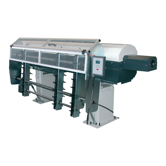
- Page 17 CHAPTER 2: TECHNICAL DATA Pusher Pusher belt drive Pusher guiding element Remote control Main access cover Pusher holding system Interface plug (not visible here) Measuring cell Front stand Retraction system Rear stand Bar stock chain loader Electrical cabinet MOVE S2...
- Page 18 CHAPTER 2: TECHNICAL DATA MOVE S2...
- Page 19 CHAPTER 3: SETTING INTO OPERATION MOVE S2...
- Page 20 When sea or air transports it, the second solution is recommended. Regardless of the type of packaging, the uncrating and lifting instructions recommended by LNS must be observed in order to prevent any injuries to persons and damages to objects. These instructions are stapled to the crate of the bar feeder.
- Page 21 Take out the parts, and place them in an easily accessible area for mounting the bar feeder For mounting and installing the bar feeder, it is advisable to contact LNS or its local representative. The latter cannot be held responsible for any malfunction resulting from an incorrect installation in which they did not take part.
- Page 22 The distance between the lathe and the bar feeder should not exceed 20 mm. Should an obstacle impose a greater distance, contact LNS or its local representative. The area around the lathe and the bar feeder must be cleared to allow for their maintenance and handling.
- Page 23 The alignment may be carried out using a nylon string, an optical tool, etc. If you do not have any alignment tools, contact LNS or its local representative so they may take care of the bar feeder installation. On each foot, loosen the lock nuts (A) of the leveling screws (B). Then, make sure that the weight of the bar feeder is evenly distributed over the 12 support points.
- Page 24 CHAPTER 3: SETTING INTO OPERATION The bar feeder is set at factory to the axis height of the lathe to equip with. If a different setup is required, please proceed as follows: Two different supports are available, depending on the axis height to reach : 900 -1000 055-008-014 1000 -1200...
- Page 25 CHAPTER 3: SETTING INTO OPERATION Once the bar feeder is in place, and perfectly aligned, it should be anchored to the ground to make it stable. To accomplish this, 8 anchorage points (A) have been provided. 8 anchorage bolts (B) must be furnished by the client (min. M10 x 100 mm / 1/2" x 4"). Once the anchoring bolts are tightened, check the alignment again, and correct it if necessary.
- Page 26 Particular attention should be given to the handling of electrical elements because of risks of electrocution. In case of possible electrical malfunctions, it is advisable to contact LNS or its local representative. It is strictly prohibited to make adjustments as long as the bar feeder is under electrical power.
- Page 27 The voltage of the bar feeder is indicated on the identification plate. The interface cable(s), between the bar feeder and the lathe is (are) provided by LNS. Although an example of an interface diagram is provided, the diagram for the interface corresponding to your device, essential when making the electrical connection, is located inside the electrical cabinet.
- Page 28 CHAPTER 3: SETTING INTO OPERATION The inputs and outputs designation of the interface on the PLC are indicated in chapter 5. Maintenance, section 3.6. The interface diagrams below are provided as examples. The diagram corresponding to your bar feeder is located in the electric cabinet, with the electric diagram. MOVE S2...
- Page 29 The voltage of the bar feeder is indicated on the identification plate. The LNS bar feeders are equipped with their own thermal protection systems (breakers, thermal relays and fuses, etc.). The power supply for the bar feeder should be connected to the output of a breaker mounted in the electrical control box of the lathe (10 A max.).
- Page 30 All signals from the bar feeder to the lathe shall be powered by the +24 VDC of the lathe. For the other types of connections, please contact LNS, or their local representative. This signal is part of a safety link (Emergency Stop circuit) of the bar feeder. XT8-XT9 corresponds to the Emergency Stop signal of the lathe.
- Page 31 CHAPTER 3: SETTING INTO OPERATION When the bar feeder is in alarm mode, the feeding pusher control signal should also de-energize. When the bar feeder is in normal operation, the R1 relay signal is energized. In the event of an alarm or break in the emergency stop circuit, this relay is de-energized.
- Page 32 CHAPTER 3: SETTING INTO OPERATION The options described below are an integral part of the standard equipment of the LNS bar feeders. These signals, however, are not required for the proper operation of the devices, or the safety locking for protecting persons and materials.
- Page 33 CHAPTER 4: OPERATION MOVE S2...
- Page 34 CHAPTER 4: OPERATION The motor for the bar feeder is equipped with a built-in absolute encoder that continuously controls the position of the pusher. When the bar feeder is switched off or there is a power failure, this position is kept in the memory by the amplifier.
- Page 35 CHAPTER 4: OPERATION The ergonomic and user-friendly remote control with a clear built-in display facilitates the handling of the bar feeder. Depending on the sequence under way, the bar feeder gives access only to those functions which are available, thus avoiding any incorrect handling, and reducing the access time to the necessary functions.
- Page 36 CHAPTER 4: OPERATION The liquid crystal display provides the operator with all the necessary data, both for handling the bar feeder and for maintenance. The upper portion of the display has eleven lines and is reserved for the reading of text. Error messages are usually displayed with their diagnostics.
- Page 37 CHAPTER 4: OPERATION These keys are located right below the display. The functions attributed to them are indicated on the display by icons. As the operator advances in the handling, the functions of the keys are automatically reattributed. The risk of error in handling is therefore virtually reduced given that the proposed functions always correspond to the circumstance and availability of the bar feeder.
- Page 38 CHAPTER 4: OPERATION To facilitate these tasks, the MOVE S2 can be equipped with a retraction system, which allows the operator to move the bar feeder. The rigidity of the system guarantees a perfect alignment when the bar feeder is in working position. A safety switch impedes any handling as long as the bar feeder is not in operational position.
- Page 39 CHAPTER 4: OPERATION Please read the safety instructions provided at the beginning of this manual before handling the following devices. The guiding elements are sensitive to corrosive products. Please do wipe or clean the element with any corrosive detergent. Use a dry cloth only to wipe the oil off the element. Hydraulic oil is injected in the guiding element, which permits to hold the rotating bar in the center of the guiding element.
- Page 40 CHAPTER 4: OPERATION 6. Pusher holding system setup (only if pusher change applied first): 6.1. Remove the rest cover located at the front of the bar feeder. 6.2. Loose the holding screws (C). 6.3. Turn the holding rolls (D) and tighten the screws (C).
- Page 41 CHAPTER 4: OPERATION There are different kinds of collets that are more or less effective: a) Simple cone collet The bar is held over about 350°, over a length from 0.5 to 7 times the diameter. Efficiency : good to very good b) Bi-conical collet Clamping over 1 or 2 x 350°, over an approximate length of 1.2 times the diameter.
- Page 42 + 1 mm), but should always be larger than that of the diameter of the feeding pusher. For inserting and removing the spindle reductions, move the bar feeder using the retraction device (Chapter 4/ Point 3.1.1). Spindle reduction tubes are available from LNS, upon request. MOVE S2...
- Page 43 CHAPTER 4: OPERATION Independent of the length of the bar feeder, the bar magazine includes 3 supports. The bar stocks are lying on the hooks of these supports. When charged on the chain loader, the bar stocks should be against the front limiter (A). When loading a new bar, a gear motor moves up the bars into the bar feeder on the dropping fingers, which slow down and position the bar stock at the guiding axis.
- Page 44 CHAPTER 4: OPERATION To validate a parameter or a value, hold the key corresponding to [ENTER] until the icon disappears. The end of bar position determines the moment when the bar feed enters the loading cycle. Usually, the end of bar position is adjusted as closely as possible behind the clamping system of the lathe (approximately 5 mm or a 1/4"...
- Page 45 CHAPTER 4: OPERATION Screen "End of bar position": Press the key corresponding to the icon Depending on which sequence the bar feed is in when the parameter is selected, the available functions and icons can change : Available functions By offset correction By teaching Icon Icon...
- Page 46 CHAPTER 4: OPERATION During the loading cycle, the bar is automatically loaded and positioned into the spindle, outside the clamping device of the lathe (chuck or actuator). This positioning corresponds to a value (Z) programmed by the operator, which is equal to the distance between the measuring cell and the position of the material in the lathe clamping device.
- Page 47 CHAPTER 4: OPERATION Screen "Top cut position": Press the key corresponding to the icon Depending on which sequence the bar feed is in when the parameter is selected, the available functions and icons can change : Available functions By offset correction Teach in Icon Icon...
- Page 48 Top cut Auxiliary end of bar Torque for the bar stock loading Torque for the part feeding Allows the access to specific settings like: Language Measure unit Reference Reserved for maintenance to LNS technicians and for unlocking features/displays. MOVE S2...
- Page 49 CHAPTER 4: OPERATION All handling, adjustments, and settings that need to be done on the bar feeder for executing a part are included in the start-up. This section presents a brief explanation of the start-up parameters of the bar feeder. If parameter 2 is selected: When the material is profiled, the bar feeder will try several times (for 2 minutes), to position the bar...
- Page 50 CHAPTER 4: OPERATION When the machining of a part requires several openings of the clamping device (for ex.: a long part, or transfer of the part to the sub-spindle), some interface conflicts may occur during the feeding process. It is important for the bar feeder to be “informed”...
- Page 51 CHAPTER 4: OPERATION When machining remnants (A) of significant length, a second mode of production may be selected to machine the remainder of the stock (depending on the capabilities of the lathe). The lathe starts a second machining program and manufactures shorter parts.
- Page 52 CHAPTER 4: OPERATION This parameter determines whether the lathe or the bar feed will control the positioning of the part. Additional parameter (option): The turret is parked in position: the turret travels to the point the bar stock will be pushed to and waits that the bar feed has pushed the material to this point.
- Page 53 CHAPTER 4: OPERATION The end of bar position determines the moment when the bar feed enters the loading cycle. Usually, the end of bar position is adjusted as closely as possible behind the clamping system of the lathe (approximately 5 mm or a 1/4" behind the chuck jaws or collet pads).This will provide minimum bar stock remnant.
- Page 54 CHAPTER 4: OPERATION This parameter allows to adapt the language in which the messages will appear, depending on the country of destination of the bar feeder This parameter defines whether the measures will be indicated in millimeters or in inches. This operation allows the bar feeder to find the original position of the servo motor and the parameters when and if these have been lost.
- Page 55 CHAPTER 4: OPERATION The service parameters allow to configure the bar feeder in its environment and to adapt the interface connected to the lathe. These parameters are protected with a password, because only LNS (or certified) technician is authorized to modify them.
- Page 56 CHAPTER 4: OPERATION The bar feeder autonomy is depending on the bar stocks placed by the operator on the chain loader. This task can be performed at any time in the production cycle, without needing to open the main access cover.
- Page 57 CHAPTER 4: OPERATION MOVE S2...
- Page 58 CHAPTER 4: OPERATION A regular cleaning of the bar feeder will optimize its quality of working and increase its lifetime. Wipe down the outside of the bar feeder with a cloth and any regular detergent. For cleaning the inside of the bar feeder, use a cloth or a smooth brush, however, do not use these on any of the rollers or any other parts made of synthetic materials.
- Page 59 Particular attention should be given to the handling of electrical elements because of risks of electrocution. In case of possible electrical malfunctions, it is advisable to contact LNS or its local representative. This chapter contains all of the elements regarding the electrical circuit of the bar feeder. The electrical parts, and groups, which may require a setting, at some time or other, are described herein in detail.
- Page 60 CHAPTER 4: OPERATION MOVE S2...
- Page 61 CHAPTER 4: OPERATION 4.875/4.6 Remote control Electrical cabinet 2.210.150 Hydraulic pump motor 4.706 Servo motor (cable directly to the electrical cabinet) 4.886 Chain loader motor 220/400 VAC 4.307 Diameter setup motor for dropping fingers 4.242 Main disconnect switch 3.638 Air pressure switch 4.050 Hydraulic pressure switch 4.772...
- Page 62 CHAPTER 4: OPERATION Interface terminal blocks X2 Valves terminal blocks X3 (YV2 – YV11) Safety terminal blocks X1 (T1 – T11) 4.907 Programmable controller PCD3 (PLC) 4.507 Safety chain control 44.0105 Servo amplifier 400 W 4.419 Automatic front rest fuse 2 A 4.606 Relay dropping fingers to upper position 4.606...
- Page 63 CHAPTER 4: OPERATION To replace the fuse: Unscrew the cap a quarter of a turn to the left; Remove and replace the fuse with an identical one, and put the cap back. On the primary side, the transformer accepts a voltage of 200-480 V, 50 Hz/60 Hz. Measure the power provided by the lathe, and, if necessary, adapt the cable on the power terminal block (A).
- Page 64 CHAPTER 4: OPERATION The servo amplifier enables the programmable controller to control the movements of the motor. The input values, as well as the position of the pusher carrier, are continuously registered. The values are saved by means of a battery, and, therefore, the axes do not need to be placed at zero when the bar feeder is powered on.
- Page 65 CHAPTER 4: OPERATION Cover Open the battery compartment. Locking clip Remove the battery from its housing and replace. Close the battery compartment. "Click in" to close MOVE S2...
- Page 66 Halt: The PLC is in HALT mode. Contact your LNS dealer. Error: The PLC is in a failure mode. Contact your LNS dealer. Usually this slot is left unused, and is used for software updates through flash (red) cards. Do not insert any flash card unless instructed by LNS.
- Page 67 CHAPTER 4: OPERATION Measuring cell Valve dropping fingers Pusher lift system high Valve air blast Pusher lift system low Valve pusher guide Pusher in referencing position YV5A Valve pusher lift system high Dropping fingers down YV5B Valve pusher lift system low Dropping fingers up Relay hydraulic pump SQ11...
- Page 68 CHAPTER 4: OPERATION When the main disconnect switch is at 0/OFF, it interrupts the input of the three phases in the control cabinet of the bar feeder. To power up the bar feeder, turn (1) the switch handle to the right, to the I/ON position.
- Page 69 CHAPTER 4: OPERATION The guiding concept of the MOVE S2 bar feeder consists mainly in maintaining the bar suspended in an oil bath. The hydraulic oil is contained in the machine itself. Aspirated by a pump motor, it is injected into the front rest and the guiding blocks.
- Page 70 CHAPTER 4: OPERATION The air is conditioned by a dedicated unit, to eliminate the humidity and protect the pneumatic components. The air filtering device serves to filter air and to set its pressure before it is distributed into the pneumatic circuit of the bar feeder. The air must be furnished at a maximum pressure of 6 bar (minimum 5 bar), and whenever possible, clean and dry.
- Page 71 CHAPTER 4: OPERATION The pneumatic battery includes the control and monitoring elements of the bar feeder pneumatic circuit. 3.583 Inlets 3.582 Outlets 3.580 Silencer 4.178 Control connection plug YV 2 3.578 Valve for bar stock laying fingers YV 3 3.578 Valve for air blast control YV 4 3.578...
- Page 72 CHAPTER 4: OPERATION Directly controlled by the PLC, the electro-valves activate the pneumatic cylinders. By pressing a key (B), the pneumatic cylinders can be activated manually. This function may prove to be useful during tests or maintenance. When the (B) key is released, the pneumatic cylinder returns to its resting position (except for pneumatic cylinders activated by 2 electro-valves).
- Page 73 CHAPTER 4: OPERATION MOVE S2...
- Page 74 CHAPTER 4: OPERATION Designation Article no. Description 024.14.054 Dropping finger 024.11.024 Pusher guide 024.11.054 Pusher guide 2.210.150 Hydraulic pump motor SP 2 4.050 Hydraulic pressure switch 3.580 Silencer 4.416 Fuse connector KA1 - 6 4.606 Motor relay 4.507 Circuit breaker 4.507 Safety chain control R1 - R5...
- Page 75 CHAPTER 4: OPERATION MOVE S2...
- Page 76 CHAPTER 4: OPERATION Company name: Person in charge: Address: ZIP: City: Country: Phone: Fax: Type of device: Serial number: Quantity Ordering no. Description Expected delivery: Location and date: Signature and stamp of the company: MOVE S2...
- Page 77 CHAPTER 4: OPERATION The above is an example only. Programming may change according to the interface between the lathe and the bar feed. MOVE S2...
- Page 78 Pae les Jourdies BP 355 St-Pierre en Faucigny TEL. +33 4 50 03 93 32 FAX +33 4 50 03 93 34 GREAT BRITAIN LNS TURBO UK Limited sales@Lnsturbouk.com www.Lns-europe.com Waterside Park, Valley Way Wombwell GB – Barnsley S73 0BB TEL.
- Page 79 Naming Convention (Numeric): 1-99999999 For the FTP connection, a minimum Cat5e crossover cable is required. The following items represent the applicable functions of the LNS Parts Library. ADD PART (F3-ENTER): If part exists there will be a prompt to overwrite...
- Page 80 CHAPITRE 6: ANNEXES Adding parts to the library requires a few simple steps. Once the process is complete, a copy of the current parameters will be stored out to the memory module under a given name (numeric). This part can then be recalled (Loaded) when needed, after which all associated parameters will be restored as the current parameters.
- Page 81 CHAPTER 6: APPENDICES Loading and deleting parts from the library requires a few simple steps. When loading a part file, the PLC retrieves all the parameters associated to the part file and sets them as the current values. When deleting parts from the library, the part file located on the memory module is permanently erased. Step 1: In the Part Setup menu, the last page gives reference to the Parts Library;...
- Page 82 CHAPITRE 6: ANNEXES The files saved in the Parts Library can be accessed for backup purpose using an FTP Client software. This example uses FileZilla to access the saved files. It is necessary to know the IP address of the PLC in order to access the files located on the memory card in slot M1 of the PLC.
- Page 83 CHAPTER 6: APPENDICES When closing the FTP session it is important to use the disconnect function of the FTP Client. This closes the session on the PLC. If the disconnect function is not used the FTP session on the PLC is not closed and remains open. This can create problems if try to reconnect without power cycling the PLC.
Need help?
Do you have a question about the QUICK SIX S2 and is the answer not in the manual?
Questions and answers