
Related Manuals for LNS SERVO S3 T


Summary of Contents for LNS SERVO S3 T
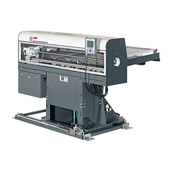
- Page 1 QUICK LOAD SERVO S3 T BARFEED Instruction Manual For CNC machine tool peripherals, it’s LNS , then all the rest 9.021.04.US...
-
Page 3: Table Of Contents
V05.1 TABLE OF CONTENTS CHAPTER 1: BASIC PRINCIPLES ............3 STRUCTURE ..........................4 RIGHTS ............................. 5 CE DECLARATION OF CONFORMITY ................... 6 SAFETY INSTRUCTIONS ......................7 SAFETY DEVICES ........................8 CHAPTER 2: TECHNICAL DATA ............9 CHARACTERISTICS....................... 10 FLOOR PLAN .......................... 10 LAYOUT OF THE ELEMENTS .................... - Page 4 TOP-CUT POSITION ......................101 POWERING DOWN ......................102 CHAPTER 8: MALFUNCTIONS/MAINTENANCE ......103 ALARMS ..........................104 MAINTENANCE ........................113 CHAPTER 9: APPENDICES ............... 115 ORDERING FORM ....................... 116 PROGRAMMING EXAMPLE ....................117 LNS ADDRESSES & CONTACTS ..................118 QUICK LOAD SERVO S3T...
-
Page 5: Chapter 1: Basic Principles
CHAPTER 1: BASIC PRINCIPLES CHAPTER 1: BASIC PRINCIPLES QUICK LOAD SERVO S3T... -
Page 6: Structure
(see chapter *) or (see point *). 1.2. Captions Whenever possible, the reference numbers contained in the instruction manual are shown with the LNS ordering number of the indicated element. To make it easier to place an order of supplies, a form has been included in the annex at the end of this manual. -
Page 7: Rights
LNS and its subsidiaries cannot be held liable for the debts, losses, expenses, or damage incurred, or suffered, by the buyer of this product, or a third party, following an accident, incorrect use, or misuse, or stemming from modifications, repairs, or transformations not authorised by LNS. -
Page 8: Ce Declaration Of Conformity
We hereby declare that the following machinery is manufactured in compliance with the following directives: - Machinery directive: 2006/42/EC - Low voltage directive: 2006/95/EC - EMC directive: 2004/108/EC LNS SA Manufacturer: Route de Frinvillier CH- 2534 Orvin Switzerland Technical Dossier Compiled by:Plaseco Kurt De Pauw Chemin des Petits-Clos 12 CH- 1744 Chénens... -
Page 9: Safety Instructions
All persons working with this device must have read and understood the instructions in this manual. LNS accepts no responsibility for possible accidents or property damage caused when safety instructions are not followed. -
Page 10: Safety Devices
By pressing the emergency stop button located on the remote control, the functions of the bar feeder and the lathe are immediately stopped. LNS, or its local representative, may not be held liable for any accidents or property damage which occur, whether caused directly or not, by any means whatsoever, if certain safety devices have been excluded. -
Page 11: Chapter 2: Technical Data
CHAPTER 2: TECHNICAL DATA CHAPTER 2: TECHNICAL DATA QUICK LOAD SERVO S3T... -
Page 12: Characteristics
CHAPTER 2: TECHNICAL DATA CHARACTERISTICS Note: Depending on the options, these technical data may vary. Please refer to the technical data sheet. Weight 1260 lbs 570 kg Overall length 80.6 in 2048 mm Overall width 58.5 in 1486 mm Depth of the bar magazine 39.4 in 1000 mm Height... - Page 13 CHAPTER 2: TECHNICAL DATA 2.1. Loading from the rear/left, transverse movement QUICK LOAD SERVO S3T...
- Page 14 CHAPTER 2: TECHNICAL DATA 2.2. Loading from the rear/left, longitudinal movement QUICK LOAD SERVO S3T...
- Page 15 CHAPTER 2: TECHNICAL DATA 2.3. Loading from the front/left, transverse movement QUICK LOAD SERVO S3T...
- Page 16 CHAPTER 2: TECHNICAL DATA 2.4. Loading from the front/left, longitudinal movement QUICK LOAD SERVO S3T...
-
Page 17: Layout Of The Elements
CHAPTER 2: TECHNICAL DATA LAYOUT OF THE ELEMENTS Designation Description Protection grid for the bar magazine Bar magazine Loading table support Retraction device Electrical cabinet Protection cover Air handling Interface plug (depending on the interface; not visible) Remote control Carriage Pusher (not visible) Loading table Positioning stops... - Page 18 CHAPTER 2: TECHNICAL DATA QUICK LOAD SERVO S3T...
-
Page 19: Chapter 3: System Start Up
CHAPTER 3: SYSTEM START UP CHAPTER 3: SYSTEM START UP QUICK LOAD SERVO S3T... -
Page 20: Transportation
CHAPTER 3: SYSTEM START UP TRANSPORTATION Please read the safety instructions provided at the beginning of this manual before handling the following devices. 1.1. Description Depending on its destination, the bar feeder may be delivered either on a pallet, or packed in a wooden crate. - Page 21 CHAPTER 3: SYSTEM START UP The bar feeder is always delivered as follows: • The magazine (A) is assembled on the bar feeder, the loading table support (B) is dismantled, the outer side of the magazine rests on the pallet. •...
- Page 22 1.3. Preparation for mounting For mounting and installing the bar feeder, it is advisable to contact LNS or one of its agents. The latter cannot be held responsible for any malfunction resulting from an incorrect installation in which they did not take part.
-
Page 23: Assembly
CHAPTER 3: SYSTEM START UP ASSEMBLY 2.1. Assembly of the bar magazine If, during installation, it seems that the magazine is going to collide with the lathe, it may be moved backwards. The magazine is positioned all the way forward in the factory and must only be moved under exceptional circumstances. - Page 24 A service parameter, indicating the position of the magazine, must be changed. For this reason, only an LNS (or approved) technician is authorized to move the bar magazine. Procedure: The loading table support must be installed after the bar magazine has been moved.
- Page 25 The maximum length (L.max.) must be entered into the service parameters (only an LNS or approved technician is authorized to edit this value).
- Page 26 CHAPTER 3: SYSTEM START UP 2.4. Assembly of the retraction system Please read the safety instructions provided at the beginning of this manual before handling the following devices. Before handling the retraction mechanism, check to see that the interface cables between the lathe and the bar feeder are long enough.
- Page 27 CHAPTER 3: SYSTEM START UP Transverse assembly of the system: Move the rails to their respective sides. Bring the bearings (D) opposite the recesses (E). Push the rails (C) underneath the unit. Move the bearings apart and place them opposite the mounting holes. Insert the retaining screws (F) and screw them into the bearings (D), without tightening them.
- Page 28 CHAPTER 3: SYSTEM START UP Tighten the retaining screws (F) for the bearings (D). Slide the blades (K) underneath the rails, then screw the screws (L) until these are pushed against the blades. Install the loading table support (M). Install the bar magazine. With the screws (J), lift the bar feeder so that the base plate is 5 mm above the ground, then level the bar feeder.
- Page 29 CHAPTER 3: SYSTEM START UP Longitudinal assembly of the system: Move the rails to their respective sides. Bring the bearings (D) opposite the recesses (E). Push the rails (C) underneath the unit. Move the bearings apart and place them opposite the mounting holes. Insert the retaining screws (F) and screw them into the bearings (D), without tightening them.
- Page 30 CHAPTER 3: SYSTEM START UP Tighten the retaining screws (F) for the bearings (D). Slide the blades (K) underneath the rails, then screw the screws (L) until these are pushed against the blades. Install the loading table support (M). Install the bar magazine. With the screws (J), lift the bar feeder so that the base plate is 5 mm above the ground, then level the bar feeder.
- Page 31 CHAPTER 3: SYSTEM START UP 2.5. Adjustment of the height • Remove the plate (A). • Check that central screw (B) is pressing against the blade (D). • Carefully unscrew the 16 screws (C). • Adjust the height of the bar feeder, by loosening or tightening the central screw (B). A hexagonal tube is supplied with the unit and can be used to access the setting screw from the top, via the loading table.
- Page 32 CHAPTER 3: SYSTEM START UP 2.6. Alignment Before proceeding with the alignment of the bar feeder, ensure that the lathe is stable and preferably levelled. Reminders: • The bar feeder must be positioned as close as possible to the lathe spindle. •...
- Page 33 CHAPTER 3: SYSTEM START UP 2.7. Anchoring Once the bar feeder is in place and perfectly aligned, it should be anchored to the ground to make it stable. To accomplish this, 4x 2 anchorage points (A) have been provided. Eight anchoring bolts must be provided by the customer (minimum M10 x 100 mm). Once the anchoring bolts are tightened, check the alignment again, and correct it if necessary QUICK LOAD SERVO S3T...
-
Page 34: Electrical Connections
CHAPTER 3: SYSTEM START UP 2.8. Safety analysis for a correct incorporation Before considering assembling the machine, it is necessary to consider the following points: • Consider safety strategies that reduce risks to an acceptable level; • Define the tasks required for applications to predict and assess the need of access and / or for the approach;... -
Page 35: Chapter 4: Electrics
CHAPTER 4: ELECTRICS CHAPTER 4: ELECTRICS QUICK LOAD SERVO S3T... -
Page 36: Electrical Equipment
Please read the safety instructions provided at the beginning of this manual before handling the following devices. Particular attention should be given to the handling of electrical elements because of risks of electrocution. In case of possible electrical malfunctions, it is advisable to contact LNS or their local representative. 1.1. Description This chapter contains all of the elements regarding the electrical circuit of the bar feeder. - Page 37 CHAPTER 4: ELECTRICS 1.2. Layout of the electrical elements on the bar feeder SQ11 SQ10 SQ12 Designation Item no. Description 4.972 Remote control 24-pin interface plug with cover (depending on interface) Electrical cabinet 4.242 Main disconnect switch 44.0106 servomotor 4.307 Motor for setting the diameter 4.484 Control switch, table in lowered position...
-
Page 38: Electrical Cabinet
CHAPTER 4: ELECTRICS ELECTRICAL CABINET 2.1. Layout of the elements in the electrical cabinet Designation Item no. Description Interface terminal block X1 (YV1 – YV8) Safety blocks X3 (T1 – T6) PCD3 4.907 Programmable controller PCD3 (PLC) 44.0105 Servo amplifier 400W 4.399 1A fuse (motor M2) 4.507... - Page 39 CHAPTER 4: ELECTRICS 2.2. Description of the elements in the cabinet 2.2.1. Master switch QS1 When the main disconnect switch is at O (off), it interrupts the three-phase input in the bar feeder control cabinet. 2.2.2. Circuit breaker QF1 (4 A) Circuit breaker QF1 protects the two phases, which power the transformer.
- Page 40 CHAPTER 4: ELECTRICS 2.2.3. Transformers 230 V (T1) and 24 VDC (T2) The transformers T1 and T2 power the entire bar feeder low-voltage network, as well as a portion of the interface signals (see the INTERFACE section in this chapter). The transformer T1 has an output of 230 Volts which powers the amplifier of the SERVO motor.
- Page 41 CHAPTER 4: ELECTRICS 2.2.4. Servo amplifier The SERVO amplifier enables the programmable controller to control the movements of the motor. The input values, as well as the position of the pusher carrier, are continuously registered. The values are saved by means of a battery, and, therefore, the axes do not need to be placed at zero when the bar feeder is powered on.
- Page 42 CHAPTER 4: ELECTRICS Cover Open the battery compartment. Locking clip Remove the battery from its housing and replace. Close the battery compartment. "Click in" to close QUICK LOAD SERVO S3T...
- Page 43 Run: The PLC is in RUN mode. This is the standard mode. Halt: The PLC is in HALT mode. Contact your LNS dealer. Error: The PLC is in a failure mode. Contact your LNS dealer. M1 slot: Usually this slot is left unused, and is used for software updates through flash (red) cards. Do not insert any flash card unless instructed by LNS.
- Page 44 CHAPTER 4: ELECTRICS 2.2.6. PLC inputs / outputs Inputs Outputs Inlet Des. Description output Des. Description Safety line switch YV1A Working position valve Air pressure control unit YV1B Loading position valve SQ10 Protection cover safety switch Motor M2 raised relay (up) SQ11 Safety switch (grid protection) Motor M2 raised relay (down)
-
Page 45: Electric Diagrams
CHAPTER 4: ELECTRICS ELECTRIC DIAGRAMS QUICK LOAD SERVO S3T... -
Page 46: Interface
4.1. Description The interface cable(s), between the bar feeder and the lathe is (are) provided by LNS. Although an example of an interface diagram is provided, the diagram for the interface corresponding to your device, essential when making the electrical connection, is located inside the electrical cabinet. - Page 47 CHAPTER 4: ELECTRICS Lathe collet signal (Input A1) This signal is for checking the mode of the lathe collet (open or closed), and is mainly used for feeding parts. For safety reasons, wire a normally open contact, coming from the signal of the lathe collet.
- Page 48 Emergency Stop circuit of the lathe. 4.2.4. Options The options described below are an integral part of the standard equipment of LNS bar feeders. These signals, however, are not required for the proper operation of the devices, or the safety locking for protecting persons and materials.
-
Page 49: Chapter 5: Pneumatics
CHAPTER 5: PNEUMATICS CHAPTER 5: PNEUMATICS QUICK LOAD SERVO S3T... -
Page 50: Pneumatic Equipment
CHAPTER 5: PNEUMATICS PNEUMATIC EQUIPMENT Please read the safety instructions provided at the beginning of this manual before handling the following devices. 1.1. Description The following automatic movements of the bar feed system are done via pneumatic elements, namely: • Loading the bar onto the loading table •... -
Page 51: Air Unit
CHAPTER 5: PNEUMATICS AIR UNIT 2.1. Description The air filtering device serves to filter air and to set its pressure before it is distributed into the pneumatic circuit of the bar feeder. The air must be supplied at a minimum pressure of 5 bar and, whenever possible, clean and dry. 2.2. -
Page 52: Pneumatic Battery
CHAPTER 5: PNEUMATICS PNEUMATIC BATTERY 3.1. Description The pneumatic battery includes the control and monitoring elements of the bar feeder pneumatic circuit. 3.2. Layout of the elements Designation Description Inputs Outputs Silencer 3.3. Manual activation Directly controlled by the PLC, the solenoid valves actuate the pneumatic cylinders. The pneumatic cylinders can be activated manually by pressing a key (B). -
Page 53: Pneumatic Diagram
CHAPTER 5: PNEUMATICS PNEUMATIC DIAGRAM 4.1. Symbols Symbol Description Designation Pressure control unit Pneumatic cylinder 3.95020.A.30/3.406 Air handling 3.636 Solenoid valve YV1A/YV1B 4.2. PNEUMATIC DIAGRAMS QUICK LOAD SERVO S3T... - Page 54 CHAPTER 5: PNEUMATICS QUICK LOAD SERVO S3T...
-
Page 55: Chapter 6: General Description
CHAPTER 6: GENERAL DESCRIPTION CHAPTER 6: GENERAL DESCRIPTION QUICK LOAD SERVO S3T... -
Page 56: Bar Magazine
CHAPTER 6: GENERAL DESCRIPTION BAR MAGAZINE Please read the safety instructions provided at the beginning of this manual before handling the following devices. 1.1. Description Placed on the side of the bar feeder, the bar magazine is 1000 mm deep and can house bars of different lengths, from 300 mm to 1600 mm. - Page 57 CHAPTER 6: GENERAL DESCRIPTION 1.2. Layout of the elements SQ11 Designation Description Bar magazine Protection grid Rear limiter Loading table support Positioning stops Support rod SQ11 Safety switch QUICK LOAD SERVO S3T...
- Page 58 The maximum length (L.max.) must be entered into the service parameters (only an LNS or approved technician is authorized to edit this value). QUICK LOAD SERVO S3T...
- Page 59 1.3.4. Profiled material Depending on the profile of the bars to be loaded, additional settings and accessories are required. Please contact LNS or their local representative. QUICK LOAD SERVO S3T...
-
Page 60: Loading Table
CHAPTER 6: GENERAL DESCRIPTION LOADING TABLE Please read the safety instructions provided at the beginning of this manual before handling the following devices. 2.1. Description When they are on the magazine, the bars (A) press against the loading stops (B). The stops are arranged on an axis (C) which is coupled to the loading table (D). - Page 61 CHAPTER 6: GENERAL DESCRIPTION 2.2. Calibration of the loading table To ensure optimum loading, it is necessary that the bar is perfectly centered in the spindle, whatever its diameter or profile. Each time the diameter or profile is changed, the position of the table is automatically set according to the parameters entered by the operator.
-
Page 62: Drive Device
The length of the pushers is fixed and does not depend on the spindle length. As a safety measure, the pushers are equipped with a mechanical stop. For loading of tubes, profiled bars or short bars, optional elements may be installed. Please contact your local LNS agent for more information. QUICK LOAD SERVO S3T... -
Page 63: Loading Finger
CHAPTER 6: GENERAL DESCRIPTION 3.2. Layout of the elements 3.95020.A.30 Designation Description Carriage Loading finger Pusher Mechanical stop Linear unit Notched belt Linear unit belt (item no. 1.830) 3.95020.A.30 Locking actuator servomotor LOADING FINGER Unlike the pusher, the loading pusher must not be replaced when the bar diameter or profile changes. It is possible to load bars of the same length directly with the loading pusher, without using the pusher. -
Page 64: Pusher
CHAPTER 6: GENERAL DESCRIPTION PUSHER 5.1. Description Three pushers are provided to cover the entire bar feeder range. Each pusher has a defined range of use: Pusher diameter Item no. Range covered **6.35 mm (1/4") *021.011.022 / 6 6 mm - 15 mm (1/4" - 1/2") 12 mm (1/2") *021.011.062 16 mm - 32 mm (>2/3"... - Page 65 CHAPTER 6: GENERAL DESCRIPTION 5.3. Replacement of the pusher Bring the loading table to the working position (lowered), then place the bar feeder in the STOP position (using the remote control). Undo the retaining screws (A) enough for them to release the recess (C) which holds the pusher (B) in the connection piece (D).
- Page 66 CHAPTER 6: GENERAL DESCRIPTION 5.4. Mechanical stop The bar feeder pusher has a fixed length, which was determined to ensure it is suited to all types of lathes. To guarantee that they never collide with the collet (for example: end of bar incorrectly set or in manual mode), the bar feeder pushers are equipped with a mechanical safety stop.
- Page 67 CHAPTER 6: GENERAL DESCRIPTION 5.5. Loading of tubes Standard pushers may be used for loading of tubes, provided that the inner diameter of the tubes is less than the diameters of the pushers. If not, there are two courses of action: 1.
-
Page 68: Belt
CHAPTER 6: GENERAL DESCRIPTION BELT It is possible that, after a certain period of use, the bar feeder will indicate that the belt (A) requires tensioning, via an on-screen message. During the intervention, the belt must remain tensioned. If the belt and the toothed wheels are misaligned, the motor will lose its reference points. -
Page 69: Retraction System
CHAPTER 6: GENERAL DESCRIPTION RETRACTION SYSTEM Please read the safety instructions provided at the beginning of this manual before handling the following devices. Before handling the retraction mechanism, check to see that the interface cables between the lathe and the bar feeder are long enough. 7.1. - Page 70 CHAPTER 6: GENERAL DESCRIPTION 7.2. Layout of the elements SQ12 Designation Description Rails Bearings Mounting hooks Levers Transverse beam (longitudinal, depending on the direction fitted) Non-return device SQ12 Safety switch 7.3. Operation of the retraction system Fitted on four extremely rigid bearings (B), the bar feeder slides along two cylindrical rails (A), which guarantee its alignment, when it is in the working position.
-
Page 71: Options
CHAPTER 6: GENERAL DESCRIPTION OPTIONS Please read the safety instructions provided at the beginning of this manual before handling the following devices. 8.1. Kit for square bars An adapter for square bars must be used to enable to bar to be oriented from the table to 120°... - Page 72 CHAPTER 6: GENERAL DESCRIPTION 8.3. Loading of tubes When the bar stock to be loaded are tubes, an adapter is needed in order to create a flat surface plate between the pusher and tube. The adapter must be adapted to the outer diameter of the tube (by turning the outside of the adapter), then fitted in place of the 25 mm pusher tip.
-
Page 73: Chapter 7: Operation
CHAPTER 7: OPERATION CHAPTER 7: OPERATION QUICK LOAD SERVO S3T... -
Page 74: Powering On
CHAPTER 7: OPERATION POWERING ON Please read the safety instructions provided at the beginning of this manual before handling the following devices. The motor for the bar feeder is equipped with a built-in absolute encoder that continuously controls the position of the pusher. When the bar feeder is powered down or there is a power failure, this position is kept in the memory by the PLC. -
Page 75: Remote Control
CHAPTER 7: OPERATION REMOTE CONTROL The ergonomic and user-friendly remote control with a clear built-in display facilitates the handling of the bar feeder. Depending on the sequence under way, the bar feeder gives access only to those functions which are available, thus avoiding any incorrect handling, and reducing the access time to the necessary functions. - Page 76 CHAPTER 7: OPERATION 2.1. Display The liquid crystal display with touchscreen function provides the operator with all the necessary data, both for handling the bar feeder and for maintenance Current Current status sequence or mode Information screen Unit (mm or inch) on current action or mode Part diameter...
- Page 77 CHAPTER 7: OPERATION Switch between normal and quick feed rate (in manual mode only) to Move material to the Top-Cut position improve positioning accuracy Confirm Teach data Cancel Value modification by correction Confirm. In settings mode, to validate a new parameter or a new value, press and hold until the icon Increase value during correction setting disappears.
- Page 78 CHAPTER 7: OPERATION 2.2. Multi-function keys F1 - F4 The multi-function keys are located right below the display. The functions attributed to them are indicated on the display by icons. As the operator advances through the handling operations, the functions of the buttons are automatically reattributed.
-
Page 79: Set-Up
CHAPTER 7: OPERATION SET-UP Please read the safety instructions provided at the beginning of this manual before handling the following devices. All handling, adaptations and settings required by the bar feeder to carry out a specific job are part of the set-up. - Page 80 CHAPTER 7: OPERATION 3.1.2. Adjustment of the loading stops If the angle of the table needs to be set in between the two recommended positions, adjust the setting of the stops according to this setting. The key point is that only one bar is loaded when the loading table is raised.
- Page 81 CHAPTER 7: OPERATION 3.2. Mechanical settings for the lathe 3.2.1. Clamping method Collet There are different kinds of collets that are more or less effective: a) Single cone collet The bar is held over about 350 degrees, over a length of 0.5 to 7 times the diameter. Efficiency : good to very good b) Biconical collet Clamping over 1 or 2 x 350 degrees, over an...
- Page 82 For inserting and removing the spindle reductions, move the bar feeder using the retraction system (see Chapter 6, section 7. RETRACTION SYSTEM for more information). Spindle reduction tubes are available from LNS, upon request. QUICK LOAD SERVO S3T...
-
Page 83: Settings
CHAPTER 7: OPERATION SETTINGS Please read the safety instructions provided at the beginning of this manual before handling the following devices. 4.1. Description The bar feeder has several parameters and functions allowing the operator to configure it so that it adapts as closely as possible to the lathe on which it is installed, as well as to the production mode being employed. - Page 84 CHAPTER 7: OPERATION 4.2. Access to the functions By pressing the MENU key, it is possible to access the setting functions. To edit these parameters, the bar feeder must be in STOP mode. To validate a new parameter or a new value, keep [ENTER] pressed until the icon disappears. Depending on your lathe or your production needs, some of the parameters may not be visible.
- Page 85 CHAPTER 7: OPERATION 4.2.1. Part adjustment Form and diameter of the bar, length of part, face-off variable distance Material shape Round bar: • Outside diameter Hexagonal / square bar: • Size on flat sides • Size on corners During the bar feed cycle, the bar feeder tries several times (during 2 minutes) to insert the bar in the lathe collet or chuck.
- Page 86 CHAPTER 7: OPERATION Top-cut position(may not be visible) During feeding, the bar is inserted in the spindle and automatically positioned in the clamping unit of the lathe. This positioning corresponds to a value (Z) programmed by the operator, which is equal to the distance between the measuring cell and the position of the material in the lathe clamping device.
- Page 87 CHAPTER 7: OPERATION End of bar position (may be not visible) The end of bar position determines the moment when the bar feeder enters the loading cycle. In principle, the end of bar position is adjusted as closely as possible behind the lathe's clamping unit (approximately 5 mm) to ensure the shortest remnants.
- Page 88 This parameter must only be used when a physical limiter is in place on the bar magazine to prevent longer bars from being loaded, which could damage the lathe. Please contact your LNS agent for more information on this application. QUICK LOAD SERVO S3T...
- Page 89 CHAPTER 7: OPERATION Part feed out rate (may not be visible) This parameter is used to adapt the feed rate to the weight of the bar, for example when feeding out aluminum bars. 4.2.2. Application setup Part feed out with/without turret Part feed out with turret This parameter determines whether the lathe controls the part feeding.
- Page 90 The end of bar position does not require any particular setting for this type of work. Contact your LNS agent for more information on this application. Misc. Applications Auto cycle simulation function - Dry Run...
- Page 91 CHAPTER 7: OPERATION 4.2.3. Positions End of bar position (may be not visible) The end of bar position determines the moment when the bar feeder enters the loading cycle. In principle, the end of bar position is adjusted as closely as possible behind the lathe's clamping unit (approximately 5 mm) to ensure the shortest remnants.
- Page 92 CHAPTER 7: OPERATION Auxiliary end of bar position (may be not visible) Depending on the lathe and its options, the auxiliary end of bar may be used in several ways. For example, for the opening of an additional front rest installed at the rear of the lathe spindle. The procedure is the same as this for the end of bar signal.
- Page 93 4.2.6. Parts library The parts library is only operational if an optional memory extension card is installed on the PLC. Please contact LNS for more information. PART LIBRARY The main parts library screen shows the current state of the library.
- Page 94 CHAPTER 7: OPERATION LOAD PART This screen allows the parameters for an existing part to be recalled from the parts library and loaded into the parts parameters, by indicating its part ID. • Active part: shows the part currently loaded. •...
- Page 95 Changing these values can damage the devices and create operator safety issues. Therefore, these parameters are protected with a password, and only an LNS (or certified) technician is authorized to modify them 1. Bar feeder...
- Page 96 CHAPTER 7: OPERATION Parameter access: Loading with turret (no/yes) Parameter access: Bar feeding with or without M-code (no/yes) Parameter access: Sub spindle: fixed or mobile (no/yes) Parameter access: End of bar (yes/no) 10. Parameter access: Top-cut position (no/yes) 11. Parameter access: Lathe collet signal inversion (no/yes) 12.
- Page 97 CHAPTER 7: OPERATION 4.2.8. Help screens From any screen in manual or automatic mode, press the HELP or “?” button on the screen, displays the help screens to troubleshoot or gather information about the software and components. 1. Software This screen displays the current software running the bar feeder and its version. 2.
- Page 98 CHAPTER 7: OPERATION 3. Inputs This screen shows the current input signals being used in the barfeed. 4. Outputs This screen shows the current output signals being used in the barfeed. QUICK LOAD SERVO S3T...
- Page 99 CHAPTER 7: OPERATION 5. Alarms list This screen shows the history of the last 10 alarms. 6. Memory list This screen helps entering and monitoring specific bits (status in green/red), and register values (value in left box). QUICK LOAD SERVO S3T...
-
Page 100: Automatic Cycle
CHAPTER 7: OPERATION AUTOMATIC CYCLE 5.1. Sequential diagram START BAR LOAD NEW LOADING BAR FEED FEED IN BAR STOCK TABLE IN AUTOMATIC AUTOMATIC (SUB- MOVES MODE MODE PROGRAM) DOWN PUSHER MOVES BAR TO OPEN COLLET TOP-CUT POSITION PUSH FORWARD COMMAND FROM LATHE? LOAD NEW BAR / DWELL... -
Page 101: End Of Bar Position
CHAPTER 7: OPERATION END OF BAR POSITION 6.1. Description The end of bar position determines the moment when the bar feed enters the loading cycle. Usually, the end of bar position is adjusted as closely as possible behind the clamping system of the lathe (approximately 5 mm or a 1/4"... - Page 102 CHAPTER 7: OPERATION The remote command displays the following text : "END OF BAR POSITION". Tap the value displayed on the screen. Depending on which sequence the bar feed is in when the parameter is selected, the available functions and icons can change : Functions Conditions By offset correction...
-
Page 103: Top-Cut Position
CHAPTER 7: OPERATION TOP-CUT POSITION 7.1. Description During feeding, the bar is inserted in the spindle and automatically positioned in the clamping unit of the lathe. This positioning corresponds to a value (Z) programmed by the operator, which is equal to the distance between the measuring cell and the position of the material in the lathe clamping device. -
Page 104: Powering Down
CHAPTER 7: OPERATION [+/-] by offset correction: • Press the key corresponding to the icon [+/-]. • The current top-cut position (z) is displayed. [+/-] • Select the field named "Enter the new value", enter the correction to be considered and confirm with ok. •... -
Page 105: Chapter 8: Malfunctions/Maintenance
CHAPTER 8: MALFUNCTIONS/MAINTENANCE CHAPTER 8: MALFUNCTIONS/MAINTENANCE QUICK LOAD SERVO S3T... -
Page 106: Alarms
Please read the safety instructions provided at the beginning of this manual before handling the following devices. Particular attention should be given to the handling of electrical elements because of risks of electrocution. In case of possible electrical malfunctions, it is advisable to contact LNS or their local representative. 1.1. PLC alarms... - Page 107 CHAPTER 8: MALFUNCTIONS/MAINTENANCE AL05 - Not in use. AL06 - AIR PRESSURE TOO LOW! Description The PLC does not detect input (I1 – SP1). The problem is generated any time the air pressure is below 3 bar or 45 psi. Solutions Check the air pressure (min.
- Page 108 CHAPTER 8: MALFUNCTIONS/MAINTENANCE AL13 - SWITCH SQ1 FAULT! Description The PLC does not detect input (I8 – SQ1). Solutions Check probe SQ1. AL14 - SWITCH SQ2 FAULT! Description The PLC does not detect input (I9 – SQ2). Solutions Check probe SQ2. AL15 - FAULT WHEN LOWERING THE TABLE! Description A mechanical blockage prevents the table being lowered.
- Page 109 CHAPTER 8: MALFUNCTIONS/MAINTENANCE AL20 - LIGHT PROBE SQ3 ACTIVATED TOO SOON! Description The alarm "LIGHT PROBE SQ3 ACTIVATED TOO SOON!" is generated when the PLC detects the input (I10 – SQ3) before the safety distance has been reached during measurement of the bar. Solutions: Press the STOP button on the remote control to clear the message.
- Page 110 Check the number of collet openings in the collet settings. AL29 - Not used. AL30 - TELESCOPIC PUSHER SYSTEM FAULT Description The telescopic pusher system has caused an error. Solutions Contact your LNS agent. AL31 - Not used. AL32 - Not used. QUICK LOAD SERVO S3T...
- Page 111 AL38 - CC-LINK COMMUNICATION FAULT! Description There is a communication issue between the lathe and the bar feeder. Solutions Contact your LNS agent. AL39 - CUT OFF FEED FAULT! Description The values do not match the specifications. Solutions The value must be greater than 0 mm, up to a maximum of 50 mm.
- Page 112 CHAPTER 8: MALFUNCTIONS/MAINTENANCE AL41 - PART ID DOES NOT EXIST Description An invalid part ID was requested. Solutions Check the part ID. If necessary, create the ID before use. AL42 - FILE READ ERROR! Description File cannot be read. Solutions Check the file (when loading the part).
- Page 113 AL50 - INCOMPATIBLE AMPLIFIER FIRMWARE! Description The firmware of the servo driver is not compatible with the LNS software. Solutions Please replace the driver. (check with your LNS representative). QUICK LOAD SERVO S3T...
- Page 114 Particular attention should be given to the handling of electrical elements because of risks of electrocution. In case of possible electrical malfunctions, it is advisable to contact LNS or their local representative. Alarm code (note 2)
-
Page 115: Maintenance
At no time should cleaning products come into contact with electrical components. 2.5. Spare parts Unless written consent is provided by LNS, no addition or modification may be made to the machine or its spare parts. LNS cannot be held liable if spare parts not provided by LNS are used. - Page 116 CHAPTER 8: MALFUNCTIONS/MAINTENANCE QUICK LOAD SERVO S3T...
-
Page 117: Chapter 9: Appendices
CHAPTER 9: APPENDICES CHAPTER 9: APPENDICES QUICK LOAD SERVO S3T... -
Page 118: Ordering Form
CHAPTER 9: APPENDICES ORDERING FORM This form should be photocopied, duly filled out, and returned to your retailer or nearest LNS agent. Company name: Person in charge: Address: ZIP: City: Country: Phone: Fax: Type of device: Serial number: Qty. Order no. -
Page 119: Programming Example
CHAPTER 9: APPENDICES PROGRAMMING EXAMPLE MAIN PROGRAM N... ”M” CODE “LATHE IN AUTOMATIC CYCLE” N... SPINDLE STOP N... COOLANT OFF N... TURRET TO FEED IN POSITION N... CLAMPING UNIT OPEN N... TURRET TO FEED OUT POSITION N... END OF BAR CHECK >... -
Page 120: Lns Addresses & Contacts
CHAPTER 9: APPENDICES LNS ADDRESSES & CONTACTS LNS Europe: www.lns-europe.com LNS America: www.lns-america.com LNS Asia: www.lns-asia.com QUICK LOAD SERVO S3T...
Need help?
Do you have a question about the SERVO S3 T and is the answer not in the manual?
Questions and answers