
Related Manuals for LNS QUICK LOAD SERVO 80 S2 BARFEED


Summary of Contents for LNS QUICK LOAD SERVO 80 S2 BARFEED
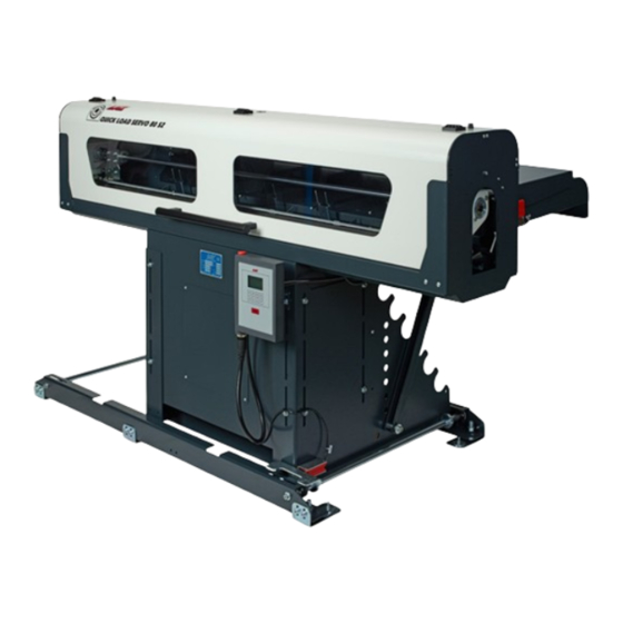
- Page 1 QUICK LOAD SERVO 80 S2 BARFEED Instruction Manual For CNC machine tool peripherals, it’s LNS , then all the rest 9.020.05.US...
-
Page 4: Table Of Contents
V04.1 TABLE OF CONTENTS CHAPTER 1 BASIC NOTIONS ................3 1. STRUCTURE ..........................4 2. RIGHTS ............................5 3. “EC” DECLARATION OF CONFORMITY ..................6 4. SAFETY INSTRUCTIONS......................7 5. SAFETY DEVICES ........................8 CHAPTER 2 TECHNICAL DATA ................ 11 1. - Page 5 8. ADDITIONAL INFORMATION ....................102 9. FTP (Parts Library Backup) ..................... 103 CHAPTER 9 APPENDICES ................105 1. ORDERING FORM ........................106 2. PROGRAMMING EXAMPLE ..................... 107 3. LNS ADDRESSES & CONTACTS ..................... 108 4. SPARE PARTS ......................... 109 QUICK LOAD SERVO 80 S2...
-
Page 6: Chapter 1 Basic Notions
CHAPTER 1: BASIC NOTIONS BASIC NOTIONS QUICK LOAD SERVO 80 S2... -
Page 7: Structure
(see chapter *) or (see point *). Captions Whenever possible, the reference numbers contained in the instruction manual are shown with the LNS ordering number of the indicated element. To make it easier to place an order of supplies, a form has been included in the annex at the end of this manual. -
Page 8: Rights
LNS SA. LNS SA and its subsidiaries cannot be held responsible for damage and problems arising from the use of options and products other than LNS products, or products approved by LNS SA. -
Page 9: Ec" Declaration Of Conformity
We hereby declare that the following machinery is manufactured in compliance with the following directives : - Machinery Directive: 2006/42/EC - Low Voltage Directive: 2014/35/EU - EMC Directive: 2014/30/EU Manufacturer : LNS SA Route de Frinvillier CH- 2534 Orvin Switzerland Technical file compiled by : Plaseco Kurt De Pauw Route de Payerne 11 CH- 1752 Villars-sur-Glâne... -
Page 10: Safety Instructions
All persons who perform work on this machine, must have read and understood the notice instructions. LNS disclaim all responsibility for possible accidents or property damage caused when safety instructions are not followed : · Do not handle the equipment without having ·... -
Page 11: Safety Devices
By pressing the emergency stop button located on the remote control, the functions of the bar feed system and the lathe are immediately stopped. The LNS company, or its local representative, may not be held responsible for possible accidents or property damage, whether caused directly or not, by any means whatsoever, if certain safety devices have not been included. - Page 12 CHAPTER 1: BASIC NOTIONS Layout of the safety elements on the bar feeder SQ10 SQ11 SQ12 This sign indicates that safety measures must be taken to avoid possible fingers/hands crushing. Designation Description Main access cover Protection cover for magazine table Emergency stop push button SQ10 Safety switch of the main access cover...
- Page 13 CHAPTER 1: BASIC NOTIONS QUICK LOAD SERVO 80 S2...
-
Page 14: Chapter 2 Technical Data
CHAPTER 2: TECHNICAL DATA TECHNICAL DATA QUICK LOAD SERVO 80 S2... -
Page 15: Characteristics
CHAPTER 2: TECHNICAL DATA 1. CHARACTERISTICS Note : Depending on the country and the standards in effect, certain technical data, such as the power supply, may vary. Please see the technical card delivered with the device. Weight 820 lbs 370 kg Dimensions See following pages Retraction travel (X and Z axis) - Page 16 CHAPTER 2: TECHNICAL DATA Loading from the left/rear with longitudinal retraction QUICK LOAD SERVO 80 S2...
- Page 17 CHAPTER 2: TECHNICAL DATA Loading from the left/rear with lateral retraction QUICK LOAD SERVO 80 S2...
- Page 18 CHAPTER 2: TECHNICAL DATA Loading from the left/front with longitudinal retraction QUICK LOAD SERVO 80 S2...
- Page 19 CHAPTER 2: TECHNICAL DATA Loading from the left/front with lateral retraction QUICK LOAD SERVO 80 S2...
-
Page 20: Layout Of The Elements
CHAPTER 2: TECHNICAL DATA 3. LAYOUT OF THE ELEMENTS Designation Description Loading magazine Protection cover Slope setting levers Protection cover holding finger Main power switch QUICK LOAD SERVO 80 S2... - Page 21 CHAPTER 2: TECHNICAL DATA QUICK LOAD SERVO 80 S2...
-
Page 22: Chapter 3 Setting Into Operation
CHAPTER 3: SETTING INTO OPERATION SETTING INTO OPERATION QUICK LOAD SERVO 80 S2... -
Page 23: Transportation
CHAPTER 3: SETTING INTO OPERATION 1. TRANSPORTATION Please read the safety precautions described at the beginning of this manual before handling the following devices. Description Depending on its destination, the QUICK LOAD SERVO 80 S2 bar feed system may be delivered either on a pallet, or packed in a wooden crate. - Page 24 CHAPTER 3: SETTING INTO OPERATION The bar feed system is always delivered as follows : · Magazine (A) is assembled on the bar feed system. · The retraction mechanism (B) is supplied partly or completely assembled, depending the moving side ordered. ·...
- Page 25 CHAPTER 3: SETTING INTO OPERATION Preparation for mounting For mounting and installing the bar feed system, it is advisable to contact LNS or one of its agents. The latter cannot be held responsible for any malfunction resulting from an incorrect installation in which they did not take part.
-
Page 26: Mounting
CHAPTER 3: SETTING INTO OPERATION 2. MOUNTING Mounting retraction device Please read the safety precautions described at the beginning of this manual before handling the following devices. Before handling the retraction mechanism, check to see that the interface cables between the spindle and the bar feed system are long enough When the bar feed system is ordered with longitudinal retraction system, it is already assembled and fixed to the machine. - Page 27 CHAPTER 3: SETTING INTO OPERATION Guiding rails Sliding wheels (not visible) Latches Latch handle Bracket (for lateral or longitudinal retraction) SQ12 Retraction system in position switch QUICK LOAD SERVO 80 S2...
- Page 28 CHAPTER 3: SETTING INTO OPERATION 2.1.1. Installing the retraction mechanism longitudinally: Bring the rails on their correct side. Put the sliding wheels (B) in front of the guiding rails (C). Push the rails (A) under the unit. Install the cross girders (D) against the rails (A). Use the levelling screws (E) to level the machine.
- Page 29 CHAPTER 3: SETTING INTO OPERATION Adjusting the table height · Check that the central screw (A) rests on the plate (B). · Carefully loosen the 8 screws (C). · Adjust the height of the bar feed system by tightening or loosening the central screw (A). ·...
- Page 30 CHAPTER 3: SETTING INTO OPERATION Alignment Before aligning the bar feed system, check to see that the lathe is stable and, if possible, levelled. Reminders: · The bar feed system should be placed as close as possible to the lathe spindle. ·...
-
Page 31: Anchoring To The Ground
4 anchorage bolts (B) must be furnished by the client (Minimum M 10 x 100 mm (1/2" x 4")). 1/2" 13-5 anchor bolts come with a new barfeed from LNS. Once the anchoring bolts are tightened, check the alignment again, and correct it if necessary. - Page 32 CHAPTER 3: SETTING INTO OPERATION QUICK LOAD SERVO 80 S2...
-
Page 33: Chapter 4 Electrics
CHAPTER 4: ELECTRICS ELECTRICS QUICK LOAD SERVO 80 S2... -
Page 34: Electrical Equipment
Please read the safety instructions provided at the beginning of this manual before handling the following devices. Particular attention should be given to the handling of electrical elements because of risks of electrocution. In case of possible electrical malfunctions, it is advisable to contact LNS or their local representative. Description This chapter contains all of the elements regarding the electrical circuit of the bar feeder. - Page 35 CHAPTER 4: ELECTRICS Layout of the electrical elements on the bar feed system SQ11 SQ10 SQ12 Designation Article No Description 4.869 Remote control station Control cabinet 44.0106 Servo motor 44.0239 Loading table motor (not visible) 44.0238 Diameter adjustment motor 4.242 Main power switch (not visible) 4.391 Loading table lower position switch...
-
Page 36: Electrical Cabinet
CHAPTER 4: ELECTRICS 2. ELECTRICAL CABINET Layout of the elements in the electrical cabinet FU1-2 PCD3 Designation Article No Description PCD3 4.917.US Programmable controller PCD3 (PLC) QUICK LOAD SERVO 80 S2... - Page 37 CHAPTER 4: ELECTRICS 44.0105 Servo amplifier 400W 4.419 Fuse 2 Amps for 24 Vdc (motor M3) 4.877 Fuse 4 Amps for 24 Vdc (motor M2) 4.507 Main contactor 4.985 Start relay 4.884 Capacitor 4.815 Circuit breaker 4A 4.242 Main disconnect switch R1-R5 4.925 Interface relay...
- Page 38 CHAPTER 4: ELECTRICS Description of the elements in the cabinet 2.2.1. Main power switch QS1 When the main disconnect switch is at O/off, it interrupts the three-phase input in the bar feeder control cabinet. 2.2.2. Circuit breaker QF1 (4 Amps) Circuit breaker QF1 protects the two phases, which power the transformer.
- Page 39 CHAPTER 4: ELECTRICS 2.2.3. Transformers 230 V (T1) and 24 VDC (T2) The transformers T1 and T2 power the entire low voltage network of the bar feed system, as well as a portion of the interface signals, (see section INTERFACE in this chapter). The transformer T1 has an output of 230 Volts which powers the amplifier of the SERVO motor A fuse installed in a support protects the transformer T1 output.
- Page 40 CHAPTER 4: ELECTRICS 2.2.4. Servo amplifier The SERVO amplifier enables the programmable controller to control the movements of the motor. The input values, as well as the position of the pusher carrier, are continuously registered. The values are saved by means of a battery, and, therefore, the axes do not need to be placed at zero when the bar feeder is powered on.
- Page 41 CHAPTER 4: ELECTRICS Cover Open the battery compartment. Locking clip Remove the battery from its housing and replace. Close the battery compartment. "Click in" to close QUICK LOAD SERVO 80 S2...
- Page 42 Run: The PLC is in RUN mode. This is the standard mode. Halt: The PLC is in HALT mode. Contact your LNS dealer. Error: The PLC is in a failure mode. Contact your LNS dealer. M1 slot: This is used to store parts library files.
- Page 43 CHAPTER 4: ELECTRICS 2.2.6. PLC inputs/outputs Inputs Outputs Input Des. Description Output Des. Description Emergency stop control circuit Loading table "up" (M2) SQ10 Main access cover safety switch Loading table "down" (M2) Loading table cover safety Diameter change reference SQ11 switch (M3) SQ12...
-
Page 44: Interface
Description The interface cable(s), between the bar feed system and the lathe is (are) provided by LNS. Although an example of an interface diagram is provided, the diagram for the interface corresponding to your device, essential when making the electrical connection, is located inside the electrical cabinet. - Page 45 CHAPTER 4: ELECTRICS Lathe clamp signal (PLC input A1) This signal is for checking the mode of the lathe clamping device (open), and is mainly used for the feeding of a part, which takes place each time the clamp opens. For safety reasons, wire a normally open contact, coming from the signal of the lathe clamp.
- Page 46 Emergency Stop button are available for connection in the Emergency Stop circuit of the lathe. 3.2.4. Options The options described below are an integral part of the standard equipment of the LNS bar feed systems. These signals, however, are not required for the proper operation of the devices, or the safety locking for protecting persons and materials.
-
Page 47: Chapter 5 General Description
CHAPTER 5: GENERAL DESCRIPTION GENERAL DESCRIPTION QUICK LOAD SERVO 80 S2... -
Page 48: Loading Magazine
CHAPTER 5: GENERAL DESCRIPTION 1. LOADING MAGAZINE Please read the safety precautions described at the beginning of this manual before handling the following devices. Description Placed to the side of the QUICK LOAD SERVO 80 S2 bar feed system, the loading magazine, 650 mm deep, can receive bars of various lengths, between 350 mm and 1600 mm. - Page 49 CHAPTER 5: GENERAL DESCRIPTION Layout of the elements SQ11 Designation Description Loading magazine Protection cover Slope setting levers SQ11 Loading table cover safety switch QUICK LOAD SERVO 80 S2...
- Page 50 CHAPTER 5: GENERAL DESCRIPTION Slope of the magazine table When profiled bar stock is loaded, and the bars do not slide easily, the slope of the table may be increased. A reference mark (A) indicates two positions: one position for round bars and another of greater slope, for profiled bars.
- Page 51 Input the maximum length (L.max.) in the Service parameters. Only LNS or its representative is allowed to change this value in the parameter. QUICK LOAD SERVO 80 S2...
- Page 52 CHAPTER 5: GENERAL DESCRIPTION 1.4.2. Loading variable bars Although the QUICK LOAD SERVO 80 S2 bar feed system can load bars of various lengths it is advisable to place them on the loading table in order of decreasing length, and to center them (A) between the limiters so that they do not go side-ways (B).
- Page 53 CHAPTER 5: GENERAL DESCRIPTION 1.4.4. Loading of profiled bars According to the profile of the bars to be loaded, some settings and some optional accessories are necessary. Please contact your LNS agent. QUICK LOAD SERVO 80 S2...
-
Page 54: Pusher Carrier
The feeding pusher faces the spindle, the feeding pusher is locked onto the carrier. The length of the feeding pushers is unvarying and does not depend on the length of the spindle. To load tubes, profiled bars or short bars, optional accessories may be installed. Please contact your local LNS representative. -
Page 55: Loading Pusher
CHAPTER 5: GENERAL DESCRIPTION 3. LOADING PUSHER Contrary to the feeding pusher, the loading pusher (B) does not need to be replaced when the bar diameter changes. Same-length bars may be loaded directly with a loading pusher without using the feeding pusher. To do this, a special extended loading pusher, available as an option, is required. -
Page 56: Feeding Pusher
CHAPTER 5: GENERAL DESCRIPTION 4. FEEDING PUSHER Description Three feeding pushers are necessary to cover the entire range of the QUICK LOAD SERVO 80 S2 barfeed system. Each pusher has a defined range of operation : Pusher diameter Diameter Range **6 mm (1/4") - Page 57 CHAPTER 5: GENERAL DESCRIPTION Pusher Replacement Bring the loading channel into working mode position (down position), then place the bar feed system into the STOP mode (remote station). Advance the carrier (A) so that the bayonet system (B) of the pusher (C) is visible. Press the bayonet's finger (B) toward the front of the bar feeder, then turn the finger a ¼...
- Page 58 CHAPTER 5: GENERAL DESCRIPTION Tubing With regard to loading the tubing, standard feeding pushers may be used as long as the inside diameter of the tubes is smaller than the outside diameter of the pushers. If this is not the case, caps (A) to be installed into the tubes (B) must be manufactured.
-
Page 59: Retraction
CHAPTER 5: GENERAL DESCRIPTION 5. RETRACTION Please read the safety precautions described at the beginning of this manual before handling the following devices. Before handling the retraction mechanism, check to see that the interface cables between the spindle and the bar feed system are long enough Description When a lathe is equipped with a bar feed system, certain elements (motors, spindle reduction tubes, etc.) become inaccessible, and sometimes it is difficult, or even impossible, to proceed with their maintenance. - Page 60 CHAPTER 5: GENERAL DESCRIPTION Layout of the elements SQ12 Designation Description Guiding rails Sliding wheels Latch handle Bracket (for lateral or longitudinal retraction) SQ12 Retraction system in position switch Use of the retraction Mounted onto four sliding wheels (B), the bar feed system slides on two cylindrical rails (A) that keep it aligned when it is in operational position.
-
Page 61: Shaft Loading Kit (Option)
CHAPTER 5: GENERAL DESCRIPTION 6. SHAFT LOADING KIT (OPTION) Please read the safety precautions described at the beginning of this manual before handling the following devices. Description This option allows the loading of shafts already machined to a defined, constant length. The shaft is directly positioned into the spindle by a shaft loading pusher replacing the loading pusher. - Page 62 CHAPTER 5: GENERAL DESCRIPTION QUICK LOAD SERVO 80 S2...
-
Page 63: Additional Shaft Loading Pusher (Option)
CHAPTER 5: GENERAL DESCRIPTION 7. ADDITIONAL SHAFT LOADING PUSHER (OPTION) Please read the safety precautions described at the beginning of this manual before handling the following devices. Description In combination with the shaft loading kit, an additional shaft loading pusher allows loading shafts of different length. -
Page 64: V-Extension Kit 120° (Option)
CHAPTER 5: GENERAL DESCRIPTION 8. V-EXTENSION KIT 120° (OPTION) Please read the safety precautions described at the beginning of this manual before handling the following devices. Description This option extends the guiding length of 150 up to 300 mm, by mounting an extension V to the front of the bar feed;... -
Page 65: Front Protection Cover (Option)
CHAPTER 5: GENERAL DESCRIPTION 9. FRONT PROTECTION COVER (OPTION) Please read the safety precautions described at the beginning of this manual before handling the following devices. Description In the case the bar feed cannot be mounted very close to the lathe, an adjustable (150 to 300 mm) front protection cover protects the working gap between the lathe and the bar feed. -
Page 66: Orientation Kit For Square Stocks (Option)
CHAPTER 5: GENERAL DESCRIPTION 10. ORIENTATION KIT FOR SQUARE STOCKS (OPTION) Please read the safety precautions described at the beginning of this manual before handling the following devices. Description A system mounted at the front exit of the bar feed allows an accurate orientation of square bar stocks to 90°, making the positioning of the bar stock easier into the clamping device of the lathe. -
Page 67: Software Options
Loading with part counter (for sub-spindle equipped lathe) During the feeding with a sub-spindle, the LNS bar feed is equipped with a part counter, allowing it to continue to manage the bar stock loading. Pre-loading shafts into a non rotating spindle liner This application allows the loading of the next shaft into a non rotating spindle liner while the current shaft is still being machined. -
Page 68: Chapter 6 Operation
CHAPTER 6: OPERATION OPERATION QUICK LOAD SERVO 80 S2... -
Page 69: Powering Up
CHAPTER 6: OPERATION 1. POWERING UP Please read the safety instructions provided at the beginning of this manual before handling the following devices. The motor of the QUICK LOAD SERVO 80 S2 bar feed system is equipped with a built-in absolute encoder that continuously controls the position of the carrier. -
Page 70: Remote Control
CHAPTER 6: OPERATION 3. REMOTE CONTROL The ergonomic and user-friendly remote control with a clear built-in display facilitates the handling of the bar feed system. Depending on the sequence under way, the bar feed system gives access only to those functions which are available, thus avoiding any incorrect handling, and reducing the access time to the necessary functions. - Page 71 CHAPTER 6: OPERATION Display The liquid crystal display provides the operator with all the necessary data, both for handling the bar feed system and for maintenance. · The upper portion of the display has eleven lines and is reserved for the reading of text. Error messages are usually displayed with their diagnostics.
- Page 72 CHAPTER 6: OPERATION Function keys F1 - F4 These keys are located right below the display. The functions attributed to them are indicated on the display by icons. As the operator advances in the handling, the functions of the keys are automatically reattributed to correspond to the circumstance and availability of the bar feed system.
-
Page 73: Lathe Mechanical Setup
CHAPTER 6: OPERATION 4. LATHE MECHANICAL SETUP Clamping method Collets There are different kinds of collets that are more or less effective: a) Simple cone collet The bar is held over about 350 degrees, over a length from 0.5 to 7 times the diameter. Efficiency : good to very good b) Bi-conical collet Clamping over 1 or 2 x 350 degrees, over an... - Page 74 + 1 mm), but should always be larger than that of the diameter of the feeding pusher. For inserting and removing the spindle reductions, move the bar feed system using the retraction device (see CHAPTER 5, RETRACTION for further information). Spindle reduction tubes are available from LNS, upon request. QUICK LOAD SERVO 80 S2...
-
Page 75: Settings
CHAPTER 6: OPERATION 5. SETTINGS Please read the safety instructions provided at the beginning of this manual before handling the following devices. Description The QUICK LOAD SERVO 80 S2 has several parameters and functions allowing the operator to configure it so that it adapts as closely as possible to the lathe on which it is installed, as well as to the production mode under way. - Page 76 · Torque for the part feeding Misc. functions Allows the access to specific settings like: · Language · Measure unit · Reference Service Reserved for maintenance to LNS technicians and for unlocking features / displays. QUICK LOAD SERVO 80 S2...
- Page 77 CHAPTER 6: OPERATION 5.2.1. Part setup All handling, adjustments, and settings that need to be done on the bar feed system for executing a part are included in the start-up. This section presents a brief explanation of the start-up parameters of the bar feed system.
- Page 78 CHAPTER 6: OPERATION Number of clamping device openings to machine the part When there is multiple openings required to machine a piece (1 and NUMBER OF CLAMPING DEVICE OPENINGS 2), interface conflicts can occur FOR OVERALL PART during the bar feed. If for instance, LENGTH: [@] the bar feed is controlled by the clamping device signal, it might...
- Page 79 CHAPTER 6: OPERATION Auxiliary end of bar position (option) AUXILIARY END OF BAR POSITION: Depending on the lathe and its interface, the auxiliary end of bar may [@@@@]MM be used in several ways, for example, to control the opening and the closing of an additional steady rest in the lathe.
- Page 80 CHAPTER 6: OPERATION 5.2.2. Application setup Loading with turret APPLICATION PRM[@] 1:WITH TURRET This parameter determines 2:WITHOUT TURRET whether the lathe or the bar feed will control the positioning of the part. ENTER Additional parameters: a) The turret is parked in position: WITH TURRET: the turret travels to the point the bar stock will be pushed to and waits that the bar feed has pushed the material to this...
- Page 81 CHAPTER 6: OPERATION 5.2.3. Position / torque End of bar position POSITION The end of bar position determines the moment when the bar feed END OF BAR SIGNAL: enters the loading cycle. [@@@@]MM Usually, the end of bar position is adjusted as closely as possible behind the clamping system of the lathe (approximately 5 mm or a 1/4"...
- Page 82 CHAPTER 6: OPERATION 5.2.4. Miscellaneous functions LANGUAGE: [@] Language selection 1:FRANÇAIS 2:ENGLISH 3:DEUTSCH This parameter allows to adapt the language in which the 4:ITALIANO messages will appear, depending on the country of destination of 5:ESPANOL the bar feed system (for practical reason, it is not necessary to stop the bar feeder to select a language).
- Page 83 The service parameters allow to configure the barfeed system in ist environment and to adapt the interface connected tot he lathe. These parameters are protected with a password, because only LNS (or certified) technician is authorized to modify them. SERVICE PARAMETERS...
-
Page 84: Automatic Cycle
CHAPTER 6: OPERATION 6. AUTOMATIC CYCLE Bar feeder movement sequences Sequence Movement Stop mode and manual functions Production cycle. Loading start. The pusher returns back to home position. Diameter selection start. The loading table starts moving up The loading flag moves to the bar stock rear. The loading flag pushes the bar stock under the measuring cell SQ3 Calculation The loading flag pushes the bar stock behind the clamping device. -
Page 85: End Of Bar Position
CHAPTER 6: OPERATION 7. END OF BAR POSITION Description The end of bar position determines the moment when the bar feed enters the loading cycle. Usually, the end of bar position is adjusted as closely as possible behind the clamping system of the lathe (approximately 5 mm or a 1/4"... - Page 86 CHAPTER 6: OPERATION Press the key corresponding to the icon [SET]. Depending on which sequence the bar feed is in when the parameter is selected, the [SET] available functions and icons can change : Available functions Conditions By offset correction By teaching Loading table down No bar stock in the loading...
-
Page 87: Top-Cut Position
CHAPTER 6: OPERATION 8. TOP-CUT POSITION Description During the loading cycle, the bar is automatically loaded and positioned into the spindle, outside the clamping device of the lathe (chuck or actuator). This positioning corresponds to a value (Z) programmed by the operator, which is equal to the distance between the measuring cell and the position of the material in the lathe clamping device. - Page 88 CHAPTER 6: OPERATION [+/-] By offset correction: · Press the key attributed to the icon [+/-]. The current top-cut position (Z) is displayed. [+/-] · Enter with the direction keys the correction to insert, and press the [+] icon to add the value, or the icon [-] to subtract it. The new value is stored. ·...
-
Page 89: Request For Reference Point
CHAPTER 6: OPERATION 9. REQUEST FOR REFERENCE POINT This function allows for locating the points of origin of the bar-feed system (positioning) Before handling the bar feeder, stop the lathe at the end of part cycle. Press the key [STOP]. [STOP] Enter the main menu. -
Page 90: Application Setup
CHAPTER 6: OPERATION 10. APPLICATION SETUP This machine allows the quick and easy selection of preconfigured applications. Following working modes are always available: 1. Feeding with turret 2. Feeding without turret 3. Miscellaneous functions (Dry Run, etc.) Additionally, depending on the lathe and the unlocked functions, following working modes may be available: 4. -
Page 91: Settings Related To Machined Parts
Following examples describe how to set a simple application. Depending on the unlocked options, several additional parameters may be added to end the setup. For other profiles than round, hex or square, please contact your local LNS representative. Example 1: round bars... - Page 92 CHAPTER 6: OPERATION Part setup – Overall part length To change the value, press any direction key. A cursor is displayed under the first [left/right] digit. [up/down] to modify the cursor position [ENTER] to modify the digit selection To store the value, press the key corresponding to the icon [ENTER]. Jump to the next screen by pressing the key corresponding to the icon [ENTER].
- Page 93 CHAPTER 6: OPERATION Example 2: hexagonal bars Bar profile hexagonal Bar diameter 50.0 mm Length of pieces to be machined 37.0 mm Thickness of the cut off tool 2.0 mm Conditions: · The loading table is in low position · 2 bars of the new diameter are on the loading table ·...
- Page 94 CHAPTER 6: OPERATION Part setup – Overall part length To change the value, press any direction key. A cursor is displayed under the first [left/right] digit. [up/down] to modify the cursor position [ENTER] to modify the digit selection To store the value, press the key corresponding to the icon [ENTER]. Jump to the next screen by pressing the key corresponding to the icon [ENTER].
- Page 95 CHAPTER 6: OPERATION Example 3: square bars Bar profile square Bar diameter 40.0 mm Length of pieces to be machined 58.0 mm Thickness of the cut off tool 2.0 mm Conditions: · The loading table is in low position · 2 bars of the new diameter are on the loading table ·...
- Page 96 CHAPTER 6: OPERATION Part setup – Overall part length To change the value, press any direction key. A cursor is displayed under the first [left/right] digit. [up/down] to modify the cursor position [ENTER] to modify the digit selection To store the value, press the key corresponding to the icon [ENTER]. Jump to the next screen by pressing the key corresponding to the icon [ENTER].
- Page 97 CHAPTER 6: OPERATION QUICK LOAD SERVO 80 S2...
-
Page 98: Chapter 7 Maintenance
CHAPTER 7: MAINTENANCE MAINTENANCE QUICK LOAD SERVO 80 S2... -
Page 99: Maintenance
At no time should cleaning products come into contact with electrical components. Spare parts Without the written consent of LNS SA, no addition or modification of the machine or spare parts can be undertaken. LNS SA assumes no responsibility when using spare parts which were not provided by LNS SA. -
Page 100: Chapter 8 Parts Library
CHAPTER 8: PARTS LIBRARY PARTS LIBRARY QUICK LOAD SERVO 80 S2... -
Page 101: Specifications
Note: For the FTP connection, a minimum Cat5e crossover cable is required. 2. FUNCTIONS Description The following items represent the applicable functions of the LNS Parts Library. ADD PART (F3-ADD): If part exists there will be a prompt to overwrite... -
Page 102: Adding Parts
CHAPTER 8: PARTS LIBRARY 3. ADDING PARTS Description Adding parts to the library requires a few simple steps. Once the process is complete, a copy of the current parameters will be stored out to the memory module under a given name (numeric). This part can then be recalled (Loaded) when needed, after which all associated parameters will be restored as the current parameters. -
Page 103: Loading / Deleting Parts
CHAPTER 8: PARTS LIBRARY Note: When attempting to save a part which already exists, a prompt will be displayed to confirm that the intent is to overwrite the existing parameter settings of that part. PART EXISTNG! OVERWRITE? Pressing F1 will overwrite the part. Pressing F4 will abort the operation and NOT overwrite the part. 4. - Page 104 CHAPTER 8: PARTS LIBRARY Step 4: A prompted will now appear asking for the confirmation that the correct changeover components have been installed. This includes (but not limited to): · Bar feed pusher · All special bar feed application adaptations ·...
-
Page 105: Additional Information
CHAPTER 8: PARTS LIBRARY Step 3: Press the F4 key (DEL). Use the up / down / left / right arrow keys to enter a Part Number. Once the part number has been established, press the F3 (ENTER).. ENTER PART NUMBER ######## ENTER Step 4:... -
Page 106: Ftp (Parts Library Backup)
CHAPTER 8: PARTS LIBRARY 6. FTP (Parts Library Backup) Description The files saved in the Parts Library can be accessed for backup purpose using an FTP Client software. This example uses FileZilla to access the saved files. Accessing the files It is necessary to know the IP address of the PLC in order to access the files located on the memory card in slot M1 of the PLC. - Page 107 CHAPTER 8: PARTS LIBRARY To create a backup copy, simply select the desired file or files and drag them to the directory which they will be stored. The files are stored at the following location on the M1 memory card: /M1_FLASH/PART Closing the FTP session When closing the FTP session it is important to use the disconnect function of the FTP Client.
-
Page 108: Chapter 9 Appendices
CHAPTER 9: APPENDICES APPENDICES QUICK LOAD SERVO 80 S2... -
Page 109: Ordering Form
CHAPTER 9: APPENDICES 1. ORDERING FORM This form should be photocopied, duly filled out, and returned to your retailer or nearest LNS agent Company name: Person in charge: Address: ZIP: City: Country: Phone: Fax: Type of device: Serial number: Qty. -
Page 110: Programming Example
CHAPTER 9: APPENDICES 2. PROGRAMMING EXAMPLE MAIN PROGRAM ”M” CODE “LATHE IN AUTOMATIC N... CYCLE” N... SPINDLE STOP N... COOLANT OFF N... TURRET TO FEED IN POSITION N... COLLET OPEN N... TURRET TO FEED OUT POSITION > SUB-PROGRAM N... END OF BAR CHECK (PROGRAM JUMP) >... -
Page 111: Lns Addresses & Contacts
CHAPTER 9: APPENDICES 3. LNS ADDRESSES & CONTACTS LNS Europe : www.lns-europe.com LNS America : www.lns-america.com LNS Asia : www.lns-asia.com QUICK LOAD SERVO 80 S2...
Need help?
Do you have a question about the QUICK LOAD SERVO 80 S2 BARFEED and is the answer not in the manual?
Questions and answers