Table of Contents
Advertisement
U B L
U B L
U B L
T R O
T R O
T R O
S P A
S P A
S P A
A N D
A N D
A N D
N U A
N U A
N U A
M A
M A
M A
C K
C K
C K
Q U I
Q U I
Q U I
C N C
C N C
C N C
n c .
a , I
r i v e
e r i c
h D
A m
T e c
4 5 2
L N S
a s t
h i o
1 E
i , O
4 6 2
n a t
6 7 4
8 . 5
c i n
7 3 3
. 5 2
C i n
8 . 5
5 1 3
3 2 0
. 5 2
n e #
8 . 8
5 1 3
. 5 2
P h o
a x #
5 1 3
m
i n f
. c o
x #
r i c a
M a
e f a
m e
v i c
S A
S e r
. L N
w w
: / / w
h t t p
O O T
O O T
O O T
E S H
E S H
E S H
P A R
P A R
P A R
R E
R E
R E
L
L
L
S I X
S I X
S I X
A
U S
4 5
I N G
I N G
I N G
T S
T S
T S
MADE IN USA
Advertisement
Table of Contents

Subscribe to Our Youtube Channel
Related Manuals for LNS QUICK SIX


Summary of Contents for LNS QUICK SIX
- Page 1 I N G I N G I N G O O T O O T O O T E S H E S H E S H P A R P A R P A R U B L U B L U B L T R O T R O...
-
Page 2: Table Of Contents
Replacing Guide Elements......................3-11 SQ1 Adjustment – Measuring Cell.....................3-13 SQ2 Adjustment – Bar Loading Detection Switch ..............3-14 SQ7 Adjustment – Home Position Proximity Switch ...............3-16 SQ12 Adjustment – Safety Reflector Switch ................3-17 SQ14 Adjustment – Dropping Finger Counting Proximity Switch..........3-19 QUICK SIX... - Page 3 Bar Magazine Rack L/R.......................6-14 Bar Magazine Rack L/F .......................6-15 Retract Switch Assembly L/R.....................6-16 Retract Switch Assembly L/F .....................6-17 Flexible Track Assembly L/F ......................6-18 Belt Drive L/R..........................6-19 Belt Drive L/F ..........................6-20 Front Pusher Support .........................6-21 Chain Loader ..........................6-22 Chain Loader L/F.........................6-23 QUICK SIX...
-
Page 4: Alarms
In conjunction with each alarm will be a brief description of what the alarm is and a few tips and procedures of how to correct the problem. Figure 1-1 Remote control station QUICK SIX... - Page 5 1 - 2 Chapter 1: Alarms SQ11 SQ12 SQ14 SQ12 QUICK SIX...
- Page 6 Main access cover safety switch SQ12 Magazine safety switch – transmitter / deflector SQ14 Dropping fingers up SQ15 Proximity switch dropping fingers 0-point SQ16 Signal A (Encoder) SQ17 Control switch main cover closed SQ18 Dropping fingers safety Emergency stop QUICK SIX...
-
Page 7: Alarm History
LNS America, Inc. for assistance and the message has already been cleared. On certain lathes, once the bar feed sends an alarm to the machine, the machine will in return send an emergency stop alarm to the bar feed which overrides any bar feed alarms. -
Page 8: A001 - Emergency Line Open
The Emergency Stop Line Open alarm occurs whenever the PLC does not detect input (I0.0). The problem is generated anytime the safety circuit contactor (K1) is not energized and all safety switches are in operating position. (Refer to the Quick Six Instruction Manual). -
Page 9: A003 - Lathe Emergency Stop Line Open
Bit 3 = 0 Reset the E-stop push button on the lathe. For case 2, after the solutions have been completed, press the STOP key on the remote control station to clear the message and reset the alarm. QUICK SIX... -
Page 10: A004 - Bar Feeder Emergency Stop
Bit 2 = 0 Reset the E-stop push button on the remote control station. For case 2, after the solution has been completed, press the STOP key on the remote control station to clear the message and reset the alarm. QUICK SIX... -
Page 11: A005 - Oil Pressure Failure
100 type oil. 76543210 Bit 6 = 0 Replace the oil pressure switch. For case 2, after the solutions have been completed, Press the STOP key on the remote control station to clear the message and reset the alarm. QUICK SIX... -
Page 12: A006 - Air Pressure Failure
(recommended) 75 psi. and no higher than 90 psi. 76543210 Bit 5 = 0 Replace the air pressure switch. For case 2, after the solutions have been completed, press the STOP key on the remote control station to clear the message and reset the alarm. QUICK SIX... -
Page 13: A007 - Main Access Cover Open
Bit 4 = 0 control station to clear the message and reset the alarm. For case 2, after the solutions have been completed, press the STOP key on the remote control station to clear the message and reset the alarm. QUICK SIX... -
Page 14: A009 - Bar Feeder Retracted
Bit 1 = 0 control station to clear the message and reset the alarm. For case 1, after the solution has been completed, press the STOP key on the remote control station to clear the message and reset the alarm. QUICK SIX... -
Page 15: A012 - Bar Magazine Indexing Interrupted
If the input still does not turn on, the problem can be isolated to a defective switch or defective cable. Replace the cable and switch. For case 2, after the solution has been completed, press the STOP key on the remote control station to clear the message and reset the alarm. QUICK SIX... -
Page 16: A023 - Servo Drive Alarm
The Servo Drive Alarm occurs if the Mitsubishi servo amplifier generates an alarm. Solution: Turn the main power off to the Quick Six for 2 seconds and turn the power back on. Note: If the alarm keeps recurring, check the alarm code on the Mitsubishi servo amplifier and refer to Mitsubishi Servo Amplifier Alarm List. -
Page 17: A024 - Servo Motor Not Ready
Verify that the PLC output (Q4.4) is turning on when the manual or automatic cycle is started. • Verify that the K1 contactor is activated; input (I0.0) should be on. If the problem persists please contact LNS America, Inc. for further information. QUICK SIX... -
Page 18: A025 - Servo Motor Positioning Error
Check the alignment between the bar feeder and the lathe. The lathe or the bar feeder may have shifted over a long period if either is not lagged to the floor securely. If the problem persists please contact an LNS agency for further information. QUICK SIX... -
Page 19: A042 - Home Position Proximity Switch Sq7 Missing
If the input still does not turn on, the problem can be isolated to a defective switch or defective cable. Replace the cable and switch. For case 2, after the solution has been completed, press the STOP key on the remote control station to clear the message and reset the alarm. QUICK SIX... -
Page 20: A044 - Bar Loading Error
Alarm needs to be cleared. Press the STOP button on the remote control station to clear and reset the alarm. Remove the bar from the spindle and restart the top-cut positioning cycle. If the problem persists please contact LNS America, Inc. for further information. QUICK SIX... -
Page 21: Servo Amplifier/Plc Communication Fault
Verify that the CN3 connector is connected properly on the servo amplifier as well as on the PLC. • Verify the 24VDC supply for the PLC. Any voltage fluctuation can result in poor performance of the PLC. If the problem persists please contact LNS America, Inc. for further information. QUICK SIX... -
Page 22: A045 - Bar Magazine Indexing Motor Faulty
Alarm needs to be cleared. Press the STOP key on the remote control station to clear the message and reset the alarm. • Make sure that the SQ2 switch is adjusted to within 0.5mm-1mm from the chain fingers. • Check that the motor is operational. If the problem persists please contact LNS America, Inc. for further information. QUICK SIX... -
Page 23: A046 - Chuck Closed Prior To Feed Out Complete
Verify that the clamping device is closing properly and that the Clamping Signal Active interface parameter is set in conjunction with how the interface signal is being sent. Verify that the correct part length has been entered in the PARAMETERS RELATED TO APPLICATIONS menu. QUICK SIX... -
Page 24: A048 - Safety Time For Part Feed Out
• Make sure that value for the OVERALL PART LENGTH is correct. • Check for any mechanical obstruction that will not allow the bar feed to reach the feed out distance. Contact LNS America, Inc. for further information. QUICK SIX... -
Page 25: A049 - Measuring Cell Sq@ Is Activated Too Early
The Measuring Cell SQ@ is Activated Too Early alarm occurs during the loading cycle if input signal (I0.7 – SQ1) turns on too early. Solution: Verify that the length of the bar that was loaded should not exceed 6’4”. The pusher is not cut to proper length or does not correspond to the “Length of Feeding Pusher.” QUICK SIX... -
Page 26: A050 - A2 Interrupted During Loading
Alarm needs to be cleared. Press the STOP key on the remote control station to clear the message and reset the alarm. Remove the bar stock from the loading channel and reset the bar feeder and the lathe in automatic cycle. QUICK SIX... -
Page 27: A053 - Lathe Did Not Resume Its Production Cycle
1 minute after reaching top-cut position. Solution: Alarm needs to be cleared. Press the STOP key on the remote control station to clear the message and reset the alarm. Restart the bar feeder and the lathe automatic cycle. QUICK SIX... -
Page 28: Pusher Support Up Motion Not Completed
Check the channel opening/closing cylinder functionality. Check the adjustment and functionality of the SQ3 and SQ4 switch. For case 1, after the solution has been completed, press the STOP key on the remote control station to clear the message and reset the alarm. QUICK SIX... -
Page 29: Pusher Support Down Motion Not Completed
Check the channel opening/closing cylinder functionality. Check the adjustment and functionality of the SQ4 switch. For case 2, after the solution has been completed, press the STOP key on the remote control station to clear the message and reset the alarm. QUICK SIX... -
Page 30: Guiding Channel First Section Not Fully Open
Check the channel opening/closing cylinder functionality. Check the adjustment and functionality of the SQ5 and SQ6 switch. For case 1, after the solution has been completed, press the STOP key on the remote control station to clear the message and reset the alarm. QUICK SIX... -
Page 31: Guiding Channel First Section Not Fully Closed
Check the channel opening/closing cylinder functionality. Check the adjustment and functionality of the SQ6 and SQ5 switch. For case 2, after the solution has been completed, press the STOP key on the remote control station to clear the message and reset the alarm. QUICK SIX... -
Page 32: Guiding Channel Second Section Not Fully Open
Check the channel opening/closing cylinder functionality. Check the adjustment and functionality of the SQ8 and SQ9 switch. For case 1, after the solution has been completed, press the STOP key on the remote control station to clear the message and reset the alarm. QUICK SIX... -
Page 33: Guiding Channel Second Section Not Fully Closed
Check the channel opening/closing cylinder functionality. Check the adjustment and functionality of the SQ8 and SQ9 switch. For case 2, after the solution has been completed, press the STOP key on the remote control station to clear the message and reset the alarm. QUICK SIX... -
Page 34: A082 - Bar Dropping Fingers Malfunction
The Bar Dropping Fingers Malfunction alarm occurs when the bar dropping fingers are returning to the home position and input signal (I2.3 – SQ15) does not turn on. Solution: Force the bar feed to do a home reference. (See Reference Procedure.) Check the adjustment and functionality of the SQ15 switch. Consult local LNS agency for more information. QUICK SIX... -
Page 35: A116 - Bar Stock Loading Error
Check that the loading flag is pushing the new bar past the 76543210 Bit 2 = 1 measuring cell (SQ3). MODULE 1 • Load bar stock onto the magazine rack. 76543210 Bit 2 = 0 • Check that the loading fingers are set to pick up a single bar. QUICK SIX... -
Page 36: A118 - Measuring Cell Sq1 Signal Defective
Bit 7 = 0 control station to clear the message and reset the alarm. For case 1, after the solution has been completed, press the STOP key on the remote control station to clear the message and reset the alarm. QUICK SIX... -
Page 37: Software Sequence
Top-cut position is achieved and is waiting for clamping device to close. Production cycle Channels open according to pusher position. Pusher retracts to home position The pusher retracts to its home position to initiate the new bar loading (SQ7 ON). QUICK SIX... - Page 38 The loading fingers rise to except new barstock and the loader rack indexes to load new bar. Verify that barstock is loaded Confirms that new barstock has been loaded (SQ2 ON) and stop loader rack indexing. Loading fingers down Loading fingers lower barstock into guiding elements. QUICK SIX...
-
Page 39: Mitsubishi Servo Amplifier Alarm List
Servo complete auto tuning. Amplifier manual Cyclic operation Position shift occurs Confirm the cumulative Pulse counting error, etc. command pulses, due to noise. cumulative feedback pulses and actual servo motor position. QUICK SIX... - Page 40 Absolute position counter warning AL.E6 Servo emergency stop warning AL.E9 Main circuit off warning Note: Deactivate the alarm about 30 minutes of cooling time after removing the cause of occurrence. 0: Pin-SG off (open) 1: Pin-SG on (short) QUICK SIX...
- Page 41 2. Encoder fault Change the servo motor. and servo amplifier. 3. Encoder cable faulty Repair or change the cable. (wire breakage or short) 4. Wrong combination of servo Use correct combination. amplifier and servo motor QUICK SIX...
- Page 42 Regenerative 6. Regenerative transistor faulty. transistor fault Checking method 1) The regenerative brake option has overheated abnormally. 2) The alarm occurs even after removal of the built-in regenerative brake resistor or regenerative brake option. QUICK SIX...
- Page 43 Parameter error Parameter setting 1. Servo amplifier fault caused the Change the servo amplifier. is wrong. parameter setting to be rewritten. 2. Regenerative brake option not Set parameter No.0 correctly. used with servo amplifier was selected in parameter No.0. QUICK SIX...
- Page 44 Change the servo motor. Checking method When the servo motor shaft is rotated with the servo off, the cumulative feedback pulses do not vary in proportion to the rotary angle of the shaft but the indication skips or returns midway. QUICK SIX...
- Page 45 88888 Watchdog CPU, parts faulty Fault of parts in servo amplifier Change servo amplifier. Checking method Alarm (88888) occurs if power is switched on after disconnection of all cables but the control circuit power supply cables. QUICK SIX...
- Page 46 EMG-SG is open. External emergency stop was made Ensure safety and emergency stop valid. (EMG-SG opened.) deactivate emergency stop. warning AL.E9 Main circuit off Servo was switched on Switch on main circuit warning with main circuit power power. off. QUICK SIX...
-
Page 48: Chapter 2
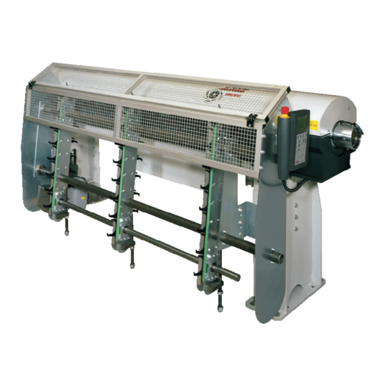
Common Issues he Quick Six is designed to be a user-friendly, simple, and reliable bar feeder, covering a range of diameters 5/16” to 3 1/8”. Although easy to use, including extremely quick changeovers and the capability for unmanned operation this unit is not flawless. -
Page 49: Low Voltage / Plc Shutdown
Description: The Quick Six uses a LNS PCD2 controller (PLC) to send/receive inputs/outputs. The PLC is powered by a +24VDC input supplied by a transformer. The input supply voltage must be regulated to ensure proper functioning. The remote control station, which is used to send/receive data back and forth with the PLC, is powered by the +24VDC on the PLC. -
Page 50: Cannot Change Application Setup Parameters
Press the “STOP” key on the remote control station and proceed with changing the parameters. Multiple Bars have been Loaded into the Channel Two bars loaded at a time Cause Solution Adjust switch SQ2. See pg. 3-14 for the procedure to Switch SQ2 is out of adjustment. properly adjust the switch. QUICK SIX... -
Page 51: Oil Is Leaking On The Floor / In The Machine
The proper guiding elements should be used to provide minimal gap between the I.D. of the elements and the O.D. of the bar stock diameter. Should not exceed 10mm overall gap (5mm per side). LNS recommends running ISO 100 hydraulic oil in the bar feed. In certain cases, a thicker oil (ISO 150) may produce better results when guiding profiled material. -
Page 52: Chapter 3
Chapter 3: Procedures 3 - 1 Chapter 3: Procedures he following chapter includes simple step-by-step procedures for mechanical adjustments, replacing damaged or faulty components and to resolve other issues related to the bar feeder. QUICK SIX... -
Page 53: Belt Tension Adjustment
Turn the belt tensioner bolt clockwise to tighten and counter-clockwise to relieve tension. The belt should be tightened so it does not sag, but it should be set firmly. Be careful not to over-tighten the belt. The belt tension should measure 5Nu. Tensioner bolt QUICK SIX... - Page 54 Chapter 3: Procedures 3 - 3 Step 8: Once the belt tension is adjusted correctly, tighten the jam nut. Tighten jam nut Step 9: Tighten the 17mm fixed hex nut. Loosen fixed hex nut Procedure complete. QUICK SIX...
-
Page 55: Pusher Changeover
Pusher support bushing Pusher Loosen the support arm 3mm bolt Step 3: Turn the pusher support bushing 90° and install it back onto the pusher support arm and tighten the 3mm bolt. 8mm → 15mm 15mm → 8mm QUICK SIX... - Page 56 Ball detent set screw Countersink Rear support Pusher support bushing Procedure complete. QUICK SIX...
-
Page 57: Cutting The Pusher
3 - 6 Chapter 3: Procedures Cutting the Pusher This procedure is used to cut the Quick Six 8mm and 15mm pushers to run bar stock up to 6’4” in length. In this procedure, both pushers will be cut. Tools List: •... - Page 58 Note: Do not completely remove the screw from the 15mm pusher tip. Loosen the screw just enough so that the tip pops out. 15mm pusher Remove tip 8mm pusher Remove tip Step 6: Cut both pushers at the EXACT same length on the mark made on the first pusher. Step 7: Drill and tap the small diameter pusher. QUICK SIX...
- Page 59 Ball detent set screw Countersink Rear support Pusher support bushing Procedure complete. QUICK SIX...
-
Page 60: Reference Procedure
Reference Procedure This procedure is used for resetting the home position of the Quick Six. This parameter allows the user to purge a reference if the bar feeder loses track of its position. BAR FEEDER LOCATION and ROTATION OF SERVO MOTOR in the BAR FEEDER SETUP should be set prior to requesting a reference. - Page 61 Once the carrier flag has reached the home position, the bar dropping fingers rotate counter-clockwise to reset the bar dropping finger home position which is detected by SQ15 (input I2.3). Procedure complete. QUICK SIX...
-
Page 62: Replacing Guide Elements
Note: The top guiding elements may be easier to pry out using a flat plated screw driver. Remove guiding elements Step 2: Loosen the thumb screw on the outboard support. Thumb screw Step 3: Remove the front nose guiding element from the inside of the outboard support. Remove guiding element QUICK SIX... - Page 63 Step 5: Tighten the thumb screw on the outboard support once the guiding element is in place. Thumb screw Step 6: Insert the correct size of guiding elements according to bar stock diameter into the bearing blocks. Procedure complete. QUICK SIX...
-
Page 64: Sq1 Adjustment - Measuring Cell
Using the small screw driver, turn the yellow screw clockwise until the LED light illuminates. Rotate yellow screw clockwise Turn until LED light illuminates Step 6: From the point when the LED light first illuminates, turn the yellow screw one full clockwise revolution. Procedure complete. QUICK SIX... -
Page 65: Sq2 Adjustment - Bar Loading Detection Switch
Tilt the top of the switch all the way back and tighten both mounting bolts while holding the switch in place. Tilt the top of the switch back Step 3: With the small screw driver, turn the yellow screw on the switch clockwise to its limit to gain adjustment. The LED light will illuminate. Turn yellow screw clockwise QUICK SIX... - Page 66 Open the lid of the bar feed and confirm that LED light does NOT turn on. If the light does illuminate, turn the yellow screw on the switch counter-clockwise until the LED light is off when the lid is open. Lid open and LED light off Procedure complete. QUICK SIX...
-
Page 67: Sq7 Adjustment - Home Position Proximity Switch
Step 2: Using a feeler gauge, adjust the switch so that there is a .5mm gap between that switch and the carrier flag. Carrier flag .5mm gap Step 3: Once the correct gap is set, tighten the lock nut on the proximity switch to hold the correct position. Lock nut Procedure complete. QUICK SIX... -
Page 68: Sq12 Adjustment - Safety Reflector Switch
Step 2: Adjust the switch up and down until the LED light illuminates. (The LED light is barely visible in the picture below. The LED light is located on top on the switch below the bracket.) LED light QUICK SIX... - Page 69 3 - 1 8 Chapter 3: Procedures Step 3: Once the LED light is illuminated, tighten both cap screws while holding the switch in place. Tighten both cap screws Procedure complete. QUICK SIX...
-
Page 70: Sq14 Adjustment - Dropping Finger Counting Proximity Switch
Note: Do not set a gap any smaller than 1mm. Setting the gap too small may cause the dropping finger to “clip” the switch. Dropping finger 1mm gap Step 3: Tighten both nuts on each side once the correct gap is set. Tighten nuts Procedure complete. QUICK SIX... - Page 72 Smart Media. Smart Media, which is mainly used in photography, has been integrated for use with the user-friendly remote control station. The Smart Media Card holds a backup program for the Quick Six if at anytime there has been a power failure or any error has occurred in the user program. In addition, it automatically backs up any application/interface parameters that have been set for the most recent application being ran.
-
Page 73: Software Update/Restore
Firmware v 1.17a Firmware v 2.08 Firmware v 2.08 (No card is present or the card is blank) If the display has firmware version 1.17a, proceed to page 4-3. If the display has firmware version 2.08, proceed to page 4-20. QUICK SIX... -
Page 74: Plc Fault
Step 3: Remove the 9 screws on the back of the pendant, and then carefully separate the back half from the front half. Step 4: Once the 2 halves are separated insert the Smart Media card (solid back side facing up and chamfered edge away from you) into the slot. Black side Chamfered edge facing up away from you QUICK SIX... - Page 75 Step 8: A password is required at this point using the number buttons on the pendant enter 3; 1; 4; 1; 5. Step 9: There are 4 menu choices on this screen, press the F3 key for PLC Fault. QUICK SIX...
- Page 76 Step 12: The PLC program will now be saved from the memory card to the PLC. This may take several minutes. Step 13: Press F4 (OK). Step 14: Turn off power to bar feeder. Step 15: Move the RUN/STOP switch to RUN position. Step 16: Restore power to the bar feeder. Procedure complete. QUICK SIX...
-
Page 77: Plc Fault
Remove the 9 screws on the back of the pendant, and then carefully separate the back half from the front half. Step 4: Once the 2 halves are separated insert the Smart Media card (solid back side facing up and chamfered edge away from you) into the slot. Black side Chamfered edge facing up away from you QUICK SIX... - Page 78 Step 8: A password is required at this point using the number buttons on the pendant enter 3; 1; 4; 1; 5. Step 9: There are 4 menu choices on this screen, press the F3 key for PLC Fault. QUICK SIX...
- Page 79 Step 11: The parameters will then be restored from the MMI to the PLC. Step 12: Press F4 (OK). Step 13: Turn off power to bar feeder. Step 14: Move the RUN/STOP switch to RUN position. Step 15: Restore power to the bar feeder. Procedure complete. QUICK SIX...
-
Page 80: Software Update
Step 3: Remove the 9 screws on the back of the pendant, and then carefully separate the back half from the front half. Step 4: Once the 2 halves are separated insert the Smart Media card (solid back side facing up and chamfered edge away from you) into the slot. Black side Chamfered edge facing up away from you QUICK SIX... - Page 81 Step 8: A password is required at this point using the number buttons on the pendant enter 3; 1; 4; 1; 5. Step 9: There are 4 menu choices on this screen, press the F2 key for Software Update. QUICK SIX...
- Page 82 Step 12: The bar feeder parameters will now be saved from the display to the PLC. Step 13: Press F4 (OK). Step 14: Turn off power to bar feeder. Step 15: Move the RUN/STOP switch to RUN position. Step 16: Restore power to the bar feeder. Procedure complete. QUICK SIX...
-
Page 83: Software Update
Step 3: Remove the 9 screws on the back of the pendant, and then carefully separate the back half from the front half. Step 4: Once the 2 halves are separated insert the Smart Media card (solid back side facing up and chamfered edge away from you) into the slot. Black side Chamfered edge facing up away from you QUICK SIX... - Page 84 Step 8: A password is required at this point using the number buttons on the pendant enter 3; 1; 4; 1; 5. Step 9: There are 4 menu choices on this screen, press the F2 key for Software Update. QUICK SIX...
- Page 85 Step 11: Press F3 to restore data from memory card to the display (text and icons). Step 12: The registers will then be restored from the memory card to the display. Step 13: Press F4 (OK). Step 14: Turn off power to bar feeder. QUICK SIX...
- Page 86 Chapter 4: Software Update/Restore 4- 15 Step 15: Move the RUN/STOP switch to RUN position. Step 16: Restore power to the bar feeder. Procedure complete. QUICK SIX...
-
Page 87: Software Update
Step 3: Remove the 9 screws on the back of the pendant, and then carefully separate the back half from the front half. Step 4: Once the 2 halves are separated insert the Smart Media card (solid back side facing up and chamfered edge away from you) into the slot. Black side Chamfered edge facing up away from you QUICK SIX... - Page 88 Step 8: A password is required at this point using the number buttons on the pendant enter 3; 1; 4; 1; 5. Step 9: There are 4 menu choices on this screen, press the F2 key for Software Update. QUICK SIX...
- Page 89 Step 11: Press F4 (PAGE DOWN) until you reach the screen to Restore PLC Program from Memory Card to PLC, press F3 (ENTER). Step 12: The PLC program will now be saved from the memory card to the PLC. This may take several minutes. QUICK SIX...
- Page 90 Chapter 4: Software Update/Restore 4- 19 Step 13: Press F4 (OK). Step 14: Turn off power to bar feeder. Step 15: Move the RUN/STOP switch to RUN position. Step 16: Restore power to the bar feeder. Procedure complete. QUICK SIX...
-
Page 91: Plc Fault - V2.08
Step 3: Remove the 9 screws on the back of the pendant, and then carefully separate the back half from the front half. Step 4: Once the 2 halves are separated insert the Smart Media card (solid back side facing up and chamfered edge away from you) into the slot. Black side Chamfered edge facing up away from you QUICK SIX... - Page 92 Step 8: A password is required at this point using the number buttons on the pendant enter 3; 1; 4; 1; 5. Step 9: There are 4 menu choices on this screen, press the F3 key for PLC Fault. QUICK SIX...
- Page 93 Step 12: Press F4 (OK). Step 13: Turn off power to bar feeder Step 14: Move the RUN/STOP switch to RUN position. Step 15: Restore power to the bar feeder. Procedure complete. QUICK SIX...
-
Page 94: Software Update - V2.08
Step 3: Remove the 9 screws on the back of the pendant, and then carefully separate the back half from the front half. Step 4: Once the 2 halves are separated insert the Smart Media card (solid back side facing up and chamfered edge away from you) into the slot. Black side Chamfered edge facing up away from you QUICK SIX... - Page 95 Step 8: A password is required at this point using the number buttons on the pendant enter 3; 1; 4; 1; 5. Step 9: There are 4 menu choices on this screen, press the F2 key for Software Update. QUICK SIX...
- Page 96 Step 11: The current parameter settings will be saved. The PLC program will then be updated and the parameters will then be restored to their previous settings. Step 12: Press F4 (OK). Step 13: Turn off power to bar feeder Step 14: Move the RUN/STOP switch to RUN position. Step 15: Restore power to the bar feeder. Procedure complete. QUICK SIX...
-
Page 98: Chapter 5
Maintenance eriodic maintenance of the Quick Six bar feeding system can only serve to improve the operation and prolong its useful life. Following a few simple steps can be extremely helpful and takes relatively no time at all. The list of maintenance... -
Page 99: Daily Maintenance
This is a wear item and it is recommended to keep spares on hand, refer to Recommended Spare Parts List . Belt Over time, it is possible that the tension of the belt may loosen up. To tighten the belt, refer to Belt Tension Adjustment procedure . QUICK SIX... -
Page 100: Annual Maintenance
Check the PLC battery The PLC backup battery saves the PLC program in case of any power failure. The battery used in the LNS PCD2 is a non- rechargeable 3VDC Lithium/ CD2032 battery. Over time, the battery will slowly discharge and an alarm message will appear on the... -
Page 102: Chapter 6
Note: When ordering parts the following information will be needed to ensure better customer support: • Bar feeder type • Bar feeder Serial Number (found on the hydraulic tank next to the air regulator) • Bar stock diameter • Lathe type (make and model) QUICK SIX... -
Page 103: Recommended Spare Parts List
Order Form pg. 6-3) Spindle Liners Ensure that the properly sized spindle liner has been installed (matches guiding channel size). Ensure that the spindle liner is straight (check total run out). Ensure that the liner is securely fastened. QUICK SIX... -
Page 104: Parts Order Form
Chapter 6: Spare Parts 6 - 3 Parts Order Form LNS America, Inc. Date: P.O. # Phone #: Bill to: Ship to: Contact: Attn: Ship via: Model of Bar feeder: Serial # of Bar feeder: Model of Lathe: Bar stock diameter: Qty. -
Page 105: Electrical Box Components
QF1/2 4.138 6.113-A Main circuit breaker (5amp) 4.242 4.242 Main disconnect switch 4.503 / 4.634 4.503 / 4.634 Main circuit breaker/Aux. contact R1-R5 4.606 6.102-A Interface relays 4.688 3 Amp Transformer 6.115-A 5 Amp, 24 VDC power supply QUICK SIX... -
Page 106: Stands
Chapter 6: Spare Parts Chapter 6: Spare Parts 6 - 5 6 - 5 Stands QUICK SIX QUICK SIX... -
Page 107: Carriage Assembly L/R
6 - 6 6 - 6 Chapter 6: Spare Parts Chapter 6: Spare Parts Carriage Assembly L/R QUICK SIX QUICK SIX... -
Page 108: Carriage Assembly L/F
Chapter 6: Spare Parts Chapter 6: Spare Parts 6 - 7 6 - 7 Carriage Assembly L/F QUICK SIX QUICK SIX... -
Page 109: Guiding Channel Cylinder
6 - 8 6 - 8 Chapter 6: Spare Parts Chapter 6: Spare Parts Guiding Channel Cylinder QUICK SIX QUICK SIX... -
Page 110: Driveshaft L/F
Chapter 6: Spare Parts Chapter 6: Spare Parts 6 - 9 6 - 9 Driveshaft L/F QUICK SIX QUICK SIX... -
Page 111: Encoder Sub-Assembly L/R
6- 10 6- 10 Chapter 6: Spare Parts Chapter 6: Spare Parts Encoder Sub-Assembly L/R QUICK SIX QUICK SIX... -
Page 112: Encoder Sub-Assembly L/F
Chapter 6: Spare Parts Chapter 6: Spare Parts 6- 11 6- 11 Encoder Sub-Assembly L/F QUICK SIX QUICK SIX... -
Page 113: Main Chassis And Cover L/R
6- 12 Chapter 6: Spare Parts Main Chassis and Cover L/R QUICK SIX... -
Page 114: Main Cover Switch Sub-Assembly L/R
Chapter 6: Spare Parts 6- 13 Main Cover Switch Sub-Assembly L/R QUICK SIX... -
Page 115: Bar Magazine Rack L/R
6- 14 Chapter 6: Spare Parts Bar Magazine Rack L/R QUICK SIX... -
Page 116: Bar Magazine Rack L/F
Chapter 6: Spare Parts 6- 15 Bar Magazine Rack L/F QUICK SIX... -
Page 117: Retract Switch Assembly L/R
6- 16 Chapter 6: Spare Parts Retract Switch Assembly L/R QUICK SIX... -
Page 118: Retract Switch Assembly L/F
Chapter 6: Spare Parts 6- 17 Retract Switch Assembly L/F QUICK SIX... -
Page 119: Flexible Track Assembly L/F
6- 18 Chapter 6: Spare Parts Flexible Track Assembly L/F QUICK SIX... -
Page 120: Belt Drive L/R
Chapter 6: Spare Parts Chapter 6: Spare Parts 6- 19 6- 19 Belt Drive L/R QUICK SIX QUICK SIX... -
Page 121: Belt Drive L/F
6- 20 6- 20 Chapter 6: Spare Parts Chapter 6: Spare Parts Belt Drive L/F QUICK SIX QUICK SIX... -
Page 122: Front Pusher Support
Chapter 6: Spare Parts Chapter 6: Spare Parts 6- 21 6- 21 Front Pusher Support QUICK SIX QUICK SIX... -
Page 123: Chain Loader
6- 22 6- 22 Chapter 6: Spare Parts Chapter 6: Spare Parts Chain Loader QUICK SIX QUICK SIX... -
Page 124: Chain Loader L/F
Chapter 6: Spare Parts 6- 23 Chain Loader L/F QUICK SIX...
Need help?
Do you have a question about the QUICK SIX and is the answer not in the manual?
Questions and answers