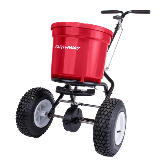
EarthWay 2150 Assembly Instructions Manual
50 lb. commercial spreader with side spread control
Hide thumbs
Also See for 2150:
- Assembly instructions manual (11 pages) ,
- Assembly and operating instructions manual (9 pages) ,
- Assembly and operating instructions manual (7 pages)
Advertisement
Quick Links
MODEL # 2150
Visit our
EarthWay
website to view the
assembly video
Prior to assembly, you will need:
Needle nose pliers
#2 Phillips screwdriver
Two 7/16" adjustable or box wrenches
2150_M51257_RevMar2021
50 lb. Commercial Spreader
with Side Spread Control
ASSEMBLY INSTRUCTIONS
SIDE SPREAD CONTROL
Your EarthWay spreader includes a
patented feature to prevent fertilizer from
being spread to the left side. To activate this
feature, slide the lever below the hopper to the back (if
standing behind the spreader) and position the left wheel
6"-12" from your sidewalk or border. This will not waste
fertilizer like competitor designs that leave 7X the
fertilizer inside the wheels from blocking material leaving
the impeller. PATENTED USPTO 10,993,368 B2
ASSEMBLY HARDWARE
AGITATOR
NUT
BEARING
¼" X 1 ½"
SCREW
BUSHING
SPREADER COMPONENTS
HANDLES
AXLE
GEAR BOX
SPACER
LOCK NUT
SM COTTER
LG COTTER PIN
¼" X 2"
¼" X 2 1/4"
HOPPER
FRAME
GUAGE
METER
REST
ROD
X-BRACE
PIVOT
IMPELLER
PAGE 1
Advertisement

Summary of Contents for EarthWay 2150
- Page 1 Side Spread Control MODEL # 2150 ASSEMBLY INSTRUCTIONS SIDE SPREAD CONTROL Visit our Your EarthWay spreader includes a EarthWay patented feature to prevent fertilizer from website to view the being spread to the left side. To activate this assembly video...
-
Page 2: Helpful Hints
Assembly and Operation Instructions HELPFUL HINTS Read the directions before assembly. If your spreader does not spread evenly, be sure “FRONT” on the GEARBOX points to the front of the spreader. The impeller must turn clockwise when pushing forward. Reversing the GEARBOX during assembly will cause issues. ... - Page 3 SHAFT into hole in center of HOPPER bottom. The word “FRONT” on the GEARBOX must point to Front of the HOPPER. NOTE: Place EarthWay brand towards the front of the hopper. (A) Install LOWER HANDLES onto FRAME to Step 5: both sides as shown.
- Page 4 AXLE (not thru the wheel). Bend with pliers to prevent pin from falling out. New for May 2021 is a fully assembled handle to reduce assembly time. Additonally, EarthWay listened to Step 9: customers who desired an adjustable handle for taller operators.
- Page 5 Assembly and Operation Instructions 2150_M51257_RevJune2021_new PAGE 5...
- Page 6 Assembly and Operation Instructions Take the shortest end of the PIVOT Step 10: ROD and insert into the SHUT-OFF PLATE. You may have two holes, use the SHUT-OFF PLATE hole towards the back of the spreader. Insert it through the hole (downward) and then rotate 90 degrees so that end is turned parrellel as shown.
- Page 7 Control Lever to #30. Next tighten each nut so that they contact the pivot Visit our bracket without moving it. Carefully tighten each nut fully so they do not loosen during EarthWay use. Recheck adjust as outlined in #1 above. website to see the...
-
Page 8: Customer Service
ONE YEAR WARRANTY EarthWay Products, Inc. warrants this product free of defects in original workmanship and materials for a period of one year to the end user with the original purchase receipt. If a manufacturing non-conformance is found, EarthWay Products, Inc. at its discretion will repair or replace the part(s)/product at no charge provided the failure is not the result of incorrect installation, mishandling, misuse, tampering, or normal wear and tear as determined by EarthWay. - Page 9 Assembly and Operation Instructions HOW TO ORDER SPARE PARTS – CALL or EMAIL: TURF DEPOT 800-305-9255 or earthway@turfdepot.com 50# (2150) Broadcast Spreader Parts List SERIES PART # DESCRIPTION SERIES PART # DESCRIPTION 40002 60602 OPERATOR HANDLES ASSEMBLY ROUND SCREEN 60332 (2.1 –...


Need help?
Do you have a question about the 2150 and is the answer not in the manual?
Questions and answers