Advertisement
Quick Links
Advertisement

Related Manuals for AMS TCS3400 EVM


Summary of Contents for AMS TCS3400 EVM
- Page 1 User guide TCS3400 EVM TCS3400 Light-To-Digital Sensor Evaluation Kit Version 1.0...
-
Page 2: Table Of Contents
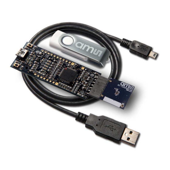
Contents Establishing basic functionality .................... 5 TCS3400 EVM graphical user interface (GUI) ..............6 Software overview ........................ 6 2.1.1 Input side, “Functional” tab ....................8 2.1.2 Input side, “Register” tab ...................... 9 2.1.3 Output side, “Functional” tab ....................13 2.1.4 Output side, “PLOT”... - Page 3 Quick Start Guide (QSG). This will load the required driver for the USB interface and also the control software and graphical user interface (GUI). The hardware consists of the EVM Controller v2.1a or v2.1c, the TCS3400 EVM daughterboard and a USB interface cable.
- Page 4 When the USB cable is connected, the green LED should flash indicating that power is being received via the USB interface, and the controller board processor is running. If the green LED does not flash, check the USB cable connections; unplug the USB cable and try again. If the green LED still does not flash, check the PC for USB error messages.
-
Page 5: Establishing Basic Functionality
Establishing basic functionality The software should be started selecting ams->TCS3400 EVM->DigitalLightSensor in the App Programs menu or by double clicking the DigitalLightSensor.exe file from the installation directory. The default installation directory, depending on the operating system you are using, is:... -
Page 6: Tcs3400 Evm Graphical User Interface (Gui)
TCS3400 device. TCS3400 EVM graphical user interface (GUI) Software overview On initialization the software displays two windows – a smaller “Digital Light Sensor” window and a larger window containing controls pertinent to the device connected. - Page 7 This window has inputs organized on the left, and outputs organized on the right. Values for register variables may be set using multiple techniques. The Functional tab is commonly used to quickly evaluate the device with nominal settings. The Input Register tab allows the register settings to be changed, and the Output Register tab allows registers to be viewed.
-
Page 8: Input Side, "Functional" Tab
Log – Creates a comma-separated values file containing the log data. The name will be assigned as explained in #3. This will cause the system to write out any data currently in the log buffer. Count of samples in the log buffer. When that number reaches the limit selected in #9, the system will show a file dialog to save the log in a named file. -
Page 9: Input Side, "Register" Tab
Wait time When the software initializes, a default wait period of 2.7mS is inserted between the ALS executions. This duration can be adjusted in 2.7mS steps from 0 to 691mS. Note that, if the WEN control bit is not turned on, the device will not insert the wait period. The WLONG bit, when enabled, causes the displayed wait time to be multiplied by a factor of 12. - Page 10 “ALS” Sub Tab The ALS tab shows the registers associated with ambient light sensing control. Register values in hex are shown on the left, preselected values are available in list boxes in the middle, and actual values are shown on the right. •...
- Page 11 “ALS Interrupt” Sub Tab This tab contains the settings for controlling the generation of ALS interrupts to a control processor. The AILTH (0x85) and AIHTH (0x87) values are 16 bit thresholds for the upper and lower trigger points. Each is set using two 8-bit registers. Another control APERS (0x8C) establishes the required persistence, 0 through F, of the interrupt signal.
- Page 12 Output side, “Register” tab The value of internal registers is displayed on this tab. Register values cannot be set here. To set registers use the Register tab on the input side of the screen. The CDATA, GDATA and BDATA and PDATA values are the ADC values for Clear and RGB photodiodes. Each is read via one 8-bit register.
-
Page 13: Output Side, "Functional" Tab
Designer’s Notebooks For additional information regarding the TCS3400, please refer to the datasheet. For information regarding the installation of the TCS3400 EVM host application software please refer to the TCS3400 EVM Quick Start Guide. Designer’s Notebooks dealing with various aspects of optical measurement and optical measurement applications are available.
Need help?
Do you have a question about the TCS3400 EVM and is the answer not in the manual?
Questions and answers