
Related Manuals for AMS AS7225


Summary of Contents for AMS AS7225
- Page 1 Demo Kit Manual AS7225 Director Demo Kit User Guide ams Demo Kit Manual Page 1 [v2-00] 2018-Jun-08 Document Feedback...
-
Page 2: Table Of Contents
LED Circuitries ........................7 Software Description ......................7 AS7225 Evaluation User Interface ..................7 Windows Terminal Application ..................... 7 AS7225 Director Demo Kit Schematics ................12 Ordering & Contact Information ..................14 Copyrights & Disclaimer ..................... 15 Revision Information ......................16... -
Page 3: Introduction
LEDs and demonstrate the close loop of Color Tuning and Daylight features. The kit also serves as a development platform that a customer microcontroller can be used to control AS7225 device as well as onboard LED strings. This user guide describes the features and functions of AS7225 Director Demo Kit. -
Page 4: Getting Started
The AS7225 Evaluation User Interface software does not need extra installation. Please copy the following files to any folder you would like to work with and run the .exe file to start the GUI. File Comment AS7225_GUI_xx_xx_xx.exe... -
Page 5: Power Supplies
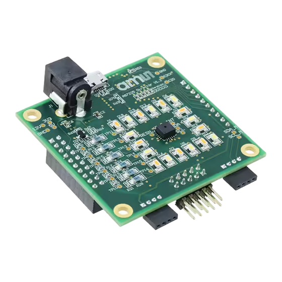
Figure 5. Devices, Connectors and LEDs Power Supplies The AS7225 Director Demo Kit is powered by 12V wall plug power adapter. The 12V supply provides the power to the LDOs as well as MOSFETs and LEDs circuitries. Onboard LDO U1 has 3.3V output, which is used for AS7225, Flash Memory, onboard MCU, and J6 for external sensors. -
Page 6: Microcontroller
When test with TSL4531, TSL4531 should be pointed to the tested area. If AS7225 demo board is used to test with a real luminaire, please point AS7225 inward for white color tuning applications and point out of the luminaire for daylighting. -
Page 7: External Mcu Connection
LED Circuitries There are six LED strings on AS7225 demo board. Each LED string has three LEDs in serial and it is controlled by a pai of MOSFETs. PWM and FB signals are used by the MCU to control the current through the LEDs. - Page 8 ATCALC <value>OK Starts new calculation Control ATINTTIME <value>OK "Set sensor integration time. Integration time = <value> x ~2.8msecs." ATGAIN <value>OK "Set sensor gain: 0=1X gain, 1=3.7X, 2=16X, 3=64X" ams Demo Kit Manual Page 8 [v2-00] 2018-Jun-08 Document Feedback...
- Page 9 ATFWL This command locks the current firmware to starts on power cycles. It rewrites the first five bytes in page0! ams Demo Kit Manual Page 9 [v2-00] 2018-Jun-08 Document Feedback...
- Page 10 Manual PWM6 override, both POLLING and INTEN have to be 0 PWM6? <value>OK Read current PWM6 setting, returning a value in [0…2047] INT? <0|1>OK Read interrupt pin state, active (0) or not active (1) ams Demo Kit Manual Page 10 [v2-00] 2018-Jun-08 Document Feedback...
- Page 11 Figure 7. Command Table Note: 1. The internal connection between Host MCU and AS7225 is via I2C communication in AS7225 evaluation demo kit and so the AT Command in Host MCU will work. For accessing the AT Command in AS7225 the Host firmware and hardware communication to AS7225 device should be configured to UART.
-
Page 12: As7225 Director Demo Kit Schematics
AS7225 Director Demo Kit User Guide AS7225 Director Demo Kit Schematics ams Demo Kit Manual Page 12 [v2-00] 2018-Jun-08 Document Feedback... - Page 13 AS7225 Director Demo Kit User Guide ams Demo Kit Manual Page 13 [v2-00] 2018-Jun-08 Document Feedback...
-
Page 14: Ordering & Contact Information
Director Demo Kit User Guide Ordering & Contact Information Ordering Code Description AS7225 DEMO KIT AS7225 Smart Light Director Demo Kit Buy our products or get free samples online at: www.ams.com/ICdirect Technical Support is available at: www.ams.com/Technical-Support Provide feedback about this document at: www.ams.com/Document-Feedback... -
Page 15: Copyrights & Disclaimer
AG shall not be liable to recipient or any third party for any damages, including but not limited to personal injury, property damage, loss of profits, loss of use, interruption of business or indirect, special, incidental or consequential damages, of any kind, in connection with or arising out of the furnishing, performance or use of the technical data herein. -
Page 16: Revision Information
ATCommand and I2C Command table was modified accoding to new firmware release 7-11 Added a Note Note: Page numbers for the previous version may differ from page numbers in the current revision. Correction of typographical errors is not explicitly mentioned. ams Demo Kit Manual Page 16 [v2-00] 2018-Jun-08 Document Feedback...
Need help?
Do you have a question about the AS7225 and is the answer not in the manual?
Questions and answers