AMS AS5600 Operation Manual
12-bit programmable contactless potentiometer
Hide thumbs
Also See for AS5600:
- Manual (14 pages) ,
- User manual (13 pages) ,
- Operation manual (10 pages)

Related Manuals for AMS AS5600


Summary of Contents for AMS AS5600
- Page 1 Operation Manual: AS5600-SO_RD_ST AS5600 12-bit Programmable Contactless Potentiometer www.ams.com Revision 1.01 / 30.06.2014 page 1/11...
-
Page 2: Table Of Contents
Mechanical Setup ......................... 5 Electrical Setup ........................6 2.4.1 3-Wire Mode ......................... 6 2.4.2 C Mode ..........................6 AS5600 Configuration ......................7 Programming the output range .................... 7 Programming a configuration ....................7 3.2.1 Low Power Mode ......................... 7 3.2.2 Hysteresis .......................... -
Page 3: General Description
The reference design allows an easy and fast evaluation of the AS5600 rotary magnetic position sensor in the lab. Additionally it is possible to replace an existing potentiometer with the AS5600- SO_RD_ST. The module is fully assembled with and pcb including the AS5600 position sensor and its necessary external components. -
Page 4: Adapter Board Description
B Ground 2.2 Adapter Board Description The AS5600 is connected over the 7-way header or by using the 3-Wire Mode. Connect the desired pins of the AS5600 using the headers and resistors. www.ams.com Revision 1.1 / 30.06.2014... -
Page 5: Mechanical Setup
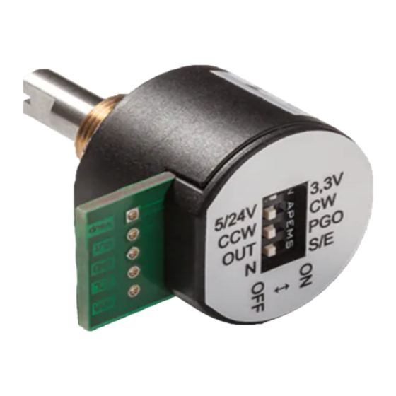
7-Way Header 2.3 Mechanical Setup The contactless potentiometer reference design comes with the AS5600-SO_RD_ST PCB assembled. The PCB holds all necessary components to operate the AS5600 in a contactless potentiometer application. The configuration of the reference module is shown in Figure... -
Page 6: Electrical Setup
The magnet is already aligned to get AGC values in the middle of the AGC range. Note: If the magnetic field seen by the AS5600 would be below 8mT, the output would be switched off and permanent angle programming would not be possible. -
Page 7: As5600 Configuration
AS5600-SO_RD_ST Operation Manual AS5600 Configuration All options to configure the AS5600 are shown below. The AS5600 operates with a default configuration if no configuration was programmed. 3.1 Programming the output range To adjust a custom angle to the full output range or to modify the Zero Position of the device, the AS5600 must be programmed. -
Page 8: Watchdog
AS5600-SO_RD_ST Operation Manual 3.2.6 Watchdog If the watchdog is active, the AS5600 automatically enters Low Power Mode 3 after one minute if the output value stays within a threshold of 4 LSB. Board Schematics, Layout and BOM The schematic, layout and BOM of the adapterboard are shown below for reference. -
Page 9: Bill Of Materials
AS5600-SO_RD_ST Operation Manual Figure 6: Reference Module PCB layout 4.3 Bill of Materials The BOM of the pcb is below in Table Table 4: Bill of Materials Designator Part Footprint Manufact Comment urer Picoblade 7 Pin Picoblade 7 Pin Header / not populated... -
Page 10: Evaluation Tools
Operation Manual Evaluation tools To configure the AS5600, no dedicated programmer is needed. For fast setup time the USB I&P Box can be used to configure the AS5600 over I C. The USB I&P Box can be ordered from the ams webpage. -
Page 11: Copyright
AG shall not be liable to recipient or any third party for any damages, including but not limited to personal injury, property damage, loss of profits, loss of use, interruption of business or indirect, special, incidental or consequential damages, of any kind, in connection with or arising out of the furnishing, performance or use of the technical data herein. - Page 12 Mouser Electronics Authorized Distributor Click to View Pricing, Inventory, Delivery & Lifecycle Information: AS5600-SO_RD_ST...
Need help?
Do you have a question about the AS5600 and is the answer not in the manual?
Questions and answers