
Related Manuals for AMS AS8579-TS EK DB


Summary of Contents for AMS AS8579-TS EK DB
- Page 1 User Guide UG000483 AS8579-TS_EK_DB User Manual (HW/SW) DemoKit Capacitive Sensor v1-01 • 2020-May-26...
-
Page 2: Table Of Contents
Document Feedback AS8579-TS_EK_DB Content Guide Content Guide Introduction ........3 Software ......... 8 Ordering Information ........3 GUI Overview and Description .....8 First Steps ........4 Revision Information ..... 9 Demo Box Content ........4 Legal Information ......10 How to Start ..........5 Hardware ........ -
Page 3: Introduction
Document Feedback AS8579-TS_EK_DB Introduction Introduction This manual explains how to use the AS8579-TS_EK_DB hardware in combination with the included software GUI. Both (HW & SW) are designed to test and evaluate the features of AS8579 capacitive sensor. The AS8579 is a sensor, which measures the capacitive value by separately measuring the 10-bit Information (accumulated to 14-bit) of I and Q. -
Page 4: First Steps
Document Feedback AS8579-TS_EK_DB First Steps First Steps Demo Box Content The AS8579-TS_EK_DB contains the following material: ● Mini USB Cable ● USB Stick (with Manual and Software) ● USB I&P Box ● AS8579 Demoboard (Hardware) Figure 1: Box Content Mini USB USB I&P Box USB Stick Cable... -
Page 5: How To Start
Document Feedback AS8579-TS_EK_DB First Steps How to Start Please use the following instructions to get the Demoboard and software running: Open AS8579-TS_EK_DB user manual and read instructions carefully (from USB Stick) Run AS5xxx_EvalSW_USB-I&P-Box_v1-6-0.exe on your PC to install the software (from USB Stick) Connect USB I&P Box with AS8579 Demoboard Check if Jumper is set to ONBoardCLK (see Figure 3:... -
Page 6: Hardware
Document Feedback AS8579-TS_EK_DB Hardware Hardware Schematic Figure 4: Schematic TP11 OBCLK VAR_SEN_out SEN1_out SEN3_out SEN5_out SEN7_out SEN9_out ECLK SEN3 SEN3_out VAR_SEN SEN1 SEN3 SEN5 SEN7 SEN9 24 Ohm EXCLK TP10 Header 3 SEN6_out SEN8_out SEN0_out SEN2_out SEN4_out 100nF SEN6 SEN8 SEN0 SEN2 SEN4... -
Page 7: Layout
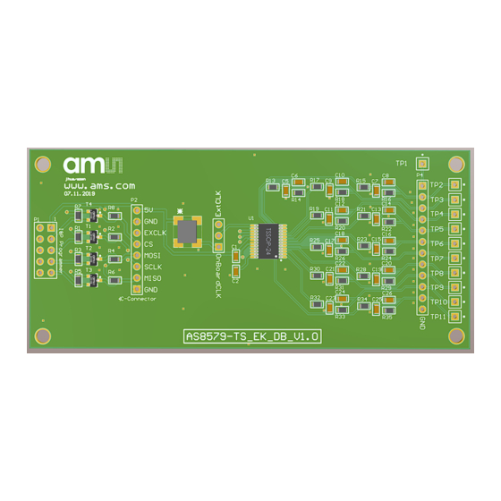
Document Feedback AS8579-TS_EK_DB Hardware Layout Figure 5: Layout Pin Assignment VAR-SEN SEN0 SEN1 SEN2 SEN3 SEN4 SEN5 SEN6 SEN7 SEN8 SEN9 Demo Kit Manual • PUBLIC UG000483 • v1-01 • 2020-May-26 │ 7... -
Page 8: Software
Document Feedback AS8579-TS_EK_DB Software Software GUI Overview and Description Figure 6: GUI Overview + Legend Legend Generic Write/Read SEN line selector + Config Load/Export Device Selector Vector Diagram for I/Q & Impedance Bar and Decimal Values for I/Q and impedance Status Flags Logging Button Connection Status of USB I&P Box... -
Page 9: Revision Information
Document Feedback AS8579-TS_EK_DB Revision Information Revision Information Changes from previous version to current revision v1-01 Page Initial version ● Page and figure numbers for the previous version may differ from page and figure numbers in the current revision. ● Correction of typographical errors is not explicitly mentioned. Demo Kit Manual •... -
Page 10: Legal Information
AG shall not be liable to recipient or any third party for any damages, including but not limited to personal injury, property damage, loss of profits, loss of use, interruption of business or indirect, special, incidental or consequential damages, of any kind, in connection with or arising out of the furnishing, performance or use of the technical data herein.
Need help?
Do you have a question about the AS8579-TS EK DB and is the answer not in the manual?
Questions and answers