Table of Contents
Advertisement
Quick Links
www.ti.com
User's Guide
ADS1x15V2EVM-PDK User's Guide
The ADS1x15V2EVM-PDK is comprised of the ADS1x15 evaluation module (EVM) and the PAMBoard
motherboard. The combination of the ADS1x15EVM and PAMBoard allows users to evaluate the functionality
of the Texas Instruments' 16-bit
both devices and EVMs. Any differences in operation between the devices or EVMs is listed separately. The
ADS1x15 devices are ultra-small, low-power, analog-to-digital converters (ADCs) with an integrated comparator.
Each ADS1x15 device has inputs that can be configured as four single-ended or two differential inputs. This
document describes both the EVM hardware platform and the graphical user interface (GUI) software used to
configure and operate the device. The user's guide also includes the EVM schematic diagram, board layout, and
bill of materials. The EVM platform eases the evaluation of the ADS1x15 device with hardware, software, and
computer connectivity through the universal serial bus (USB) interface.
SBAU362 – MARCH 2021
Submit Document Feedback
ADS1115
or the 12-bit ADS1015. ADS1x15 refers to what is common to
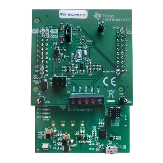
ADS1x15 Evaluation Module (ADS1115V2EVM-PDK Shown)
Related Documentation
Device
ADS1115
ADS1015
TCA9406
Copyright © 2021 Texas Instruments Incorporated
ABSTRACT
Literature Number
SBAS444
SBAS473
SCPS221
ADS1x15V2EVM-PDK User's Guide
1
Advertisement
Table of Contents

Related Manuals for Texas Instruments ADS1x15V2EVM-PDK


Summary of Contents for Texas Instruments ADS1x15V2EVM-PDK
- Page 1 User’s Guide ADS1x15V2EVM-PDK User's Guide ABSTRACT The ADS1x15V2EVM-PDK is comprised of the ADS1x15 evaluation module (EVM) and the PAMBoard motherboard. The combination of the ADS1x15EVM and PAMBoard allows users to evaluate the functionality of the Texas Instruments' 16-bit ADS1115 or the 12-bit ADS1015.
-
Page 2: Table Of Contents
(JP1)........................11 Figure 4-1. Browser Extension and TI Cloud Agent Installation....................Figure 5-1. Menu Bar Options..............................Figure 5-2. GUI Navigation Bar Options............................ Figure 5-3. ADS1x15V2EVM-PDK Connected GUI (ADS1115 shown)..................Figure 5-4. File Menu.................................15 Figure 5-5. Analysis Data Options............................. Figure 5-6. Register Data Options............................. - Page 3 ™ is a trademark of Mozilla Foundation. Chrome ™ is a trademark of Google LLC. All trademarks are the property of their respective owners. SBAU362 – MARCH 2021 ADS1x15V2EVM-PDK User's Guide Submit Document Feedback Copyright © 2021 Texas Instruments Incorporated...
-
Page 4: Introduction
The ADS1x15EVM requires an external controller to evaluate the ADS1x15 device. The PAMBoard is controlled by commands received from the ADS1x15V2EVM-PDK GUI, and returns data to the GUI for display and analysis. If the PAMBoard is not used, the EVM plug-in module format allows for an alternative external host to communicate with the ADS1x15 by connection through the pin headers J1 through J4. -
Page 5: Quick Start
ADS1115V2EVM-PDK Figure 2-1. Hardware Setup 2.2 Step 2 - USB Connection and GUI Startup The ADS1x15V2EVM-PDK GUI software can be run from a browser window. Additional software may need to be installed if not installed previously. See Section 4.2 for additional details. When the GUI has started, plug the ADS1x15V2EVM-PDK into an available USB port on the PC. -
Page 6: Step 3 - Configuration And Data Collection
4. Choose Volts from the chart window for the Y-axis drop-down menu. See Figure 2-4. 5. Press the COLLECT DATA button to capture the data. ADS1x15V2EVM-PDK User's Guide SBAU362 – MARCH 2021 Submit Document Feedback Copyright © 2021 Texas Instruments Incorporated... -
Page 7: Figure 2-4. Data Capture
Quick Start 6. The collected data appears in the chart window when the collection completes. Figure 2-4. Data Capture SBAU362 – MARCH 2021 ADS1x15V2EVM-PDK User's Guide Submit Document Feedback Copyright © 2021 Texas Instruments Incorporated... -
Page 8: Ads1X15Evm Overview
Various onboard components are used to interface the analog input, digital interface, and provide power to the ADS1x15 device. The functional block diagram shows an ADS1x15V2EVM-PDK board overview. 3.1 ADS1x15EVM-to-PAMBoard Interface The ADS1x15EVM supports the digital I C and functional modes as detailed in the... -
Page 9: Digital Interface
Figure 6-5). The EEPROM is preprogrammed with the information required to configure and initialize the ADS1x15V2EVM-PDK GUI software platform. When the hardware is initialized through the software, the EEPROM is no longer used. The PAMBoard and EEPROM (U3) use 3.3 V for the device interface logic levels. The ADS1x15 can operate at either 3.3 V or 5 V as desired by jumper selection JP1. - Page 10 The absolute input voltage is bounded by VDD + 0.3 V and GND – 0.3 V. Damage to the ADS1x15 may occur if the absolute input range is exceeded. ADS1x15V2EVM-PDK User's Guide SBAU362 – MARCH 2021 Submit Document Feedback Copyright © 2021 Texas Instruments Incorporated...
-
Page 11: Power-Supply Options
When the USB cable is plugged into the PC, two LEDs will light on the PAMBoard (Figure 3-4). The bottom LED (D5) indicates that the 5-V output is active. The top LED (D1) indicates that the ADS1x15V2EVM-PDK is ready to communicate with the GUI. Figure 3-4. LED Indicators D1 and D5... -
Page 12: Ads1X15V2Evm-Pdk Setup And Operation
4 ADS1x15V2EVM-PDK Setup and Operation The ADS1x15V2EVM-PDK requires a communication driver and GUI software for device configuration and data collection. Driver installation is automatic. The USB enumerates as a composite device for communications device class (CDC) and bulk. Commands are sent through CDC when data are collected by bulk transfers from the PAMBoard. -
Page 13: Ads1X15V2Evm-Pdk Gui
5-2) shows vertical tabs available to navigate through the various GUI displays. The vertical tabs starting at the top icon include: • Home • Chart • Configuration SBAU362 – MARCH 2021 ADS1x15V2EVM-PDK User's Guide Submit Document Feedback Copyright © 2021 Texas Instruments Incorporated... -
Page 14: Figure 5-2. Gui Navigation Bar Options
EVM connected matches with the GUI. An EEPROM on the ADS1x15V2EVM-PDK contains information specific to the EVM connected. A properly connected and identified EVM displays as Device Connected with a green indicator and at the bottom as Hardware Connected in the status ribbon. -
Page 15: Menu Bar
(CSV) formatted file for further analysis using external programs. The data can also be loaded back into the GUI for further review or analysis by selecting Load data. SBAU362 – MARCH 2021 ADS1x15V2EVM-PDK User's Guide Submit Document Feedback Copyright © 2021 Texas Instruments Incorporated... -
Page 16: Figure 5-5. Analysis Data Options
A previously saved configuration can be loaded back into the GUI again when testing various device configurations by using Load register settings. Figure 5-6. Register Data Options ADS1x15V2EVM-PDK User's Guide SBAU362 – MARCH 2021 Submit Document Feedback Copyright © 2021 Texas Instruments Incorporated... -
Page 17: Figure 5-7. Options Menu
5-8) with options to change the COM port or reconfigure the settings as necessary. Figure 5-7. Options Menu Figure 5-8. Serial Port Configuration Settings SBAU362 – MARCH 2021 ADS1x15V2EVM-PDK User's Guide Submit Document Feedback Copyright © 2021 Texas Instruments Incorporated... -
Page 18: Figure 5-9. Tools Menu
5-10) displays the activity information log at the bottom of the GUI. The Log pane displays the same information as when clicking the book icon in the status ribbon. Figure 5-9. Tools Menu Figure 5-10. Logs Display ADS1x15V2EVM-PDK User's Guide SBAU362 – MARCH 2021 Submit Document Feedback Copyright © 2021 Texas Instruments Incorporated... -
Page 19: Figure 5-11. Help Menu
5-12, information specific to the GUI build and the connected hardware is found by selecting About from the drop-down Help menu. Figure 5-12. Help Information (About) SBAU362 – MARCH 2021 ADS1x15V2EVM-PDK User's Guide Submit Document Feedback Copyright © 2021 Texas Instruments Incorporated... -
Page 20: Navigation Bar
The Home page includes links to a variety of information. These links include this user’s guide, the EVM schematic, as well as support resources. Next to the connection status indicator is an information icon. Clicking the icon displays specific information regarding the ADS1x15V2EVM-PDK, as shown in Figure 5-13. -
Page 21: Figure 5-14. Data Capture Window
Pk-to-Pk representing the total noise peak-to-peak within the data set • Eff. Res representing the effective resolution as number of bits with the value in parenthesis showing the noise-free number of bits SBAU362 – MARCH 2021 ADS1x15V2EVM-PDK User's Guide Submit Document Feedback Copyright © 2021 Texas Instruments Incorporated... -
Page 22: Figure 5-15. Capture Statistics
SFDR or spurious free dynamic range • THD or total harmonic distortion • SINAD or signal-to-noise and distortion • ENOB or effective number of bits • Harmonics ADS1x15V2EVM-PDK User's Guide SBAU362 – MARCH 2021 Submit Document Feedback Copyright © 2021 Texas Instruments Incorporated... -
Page 23: Figure 5-16. Fft Statistics
5-18) shows the number of occurrences a code or group of codes appear. User selection includes a choice of: • # of Bins selecting the number of bins to include in the plot SBAU362 – MARCH 2021 ADS1x15V2EVM-PDK User's Guide Submit Document Feedback Copyright © 2021 Texas Instruments Incorporated... -
Page 24: Figure 5-18. Histogram Plot
5-19) is rather meaningless for dc input voltages. However, a low-frequency AC signal can be analyzed and the FFT plot displayed. Figure 5-19. FFT Plot ADS1x15V2EVM-PDK User's Guide SBAU362 – MARCH 2021 Submit Document Feedback Copyright © 2021 Texas Instruments Incorporated... -
Page 25: Figure 5-20. Capture Settings
Question mark icons (?) appear throughout the Register Map window. Clicking these icons opens details pertaining to the items in the locations where they appear. SBAU362 – MARCH 2021 ADS1x15V2EVM-PDK User's Guide Submit Document Feedback Copyright © 2021 Texas Instruments Incorporated... -
Page 26: Figure 5-21. Register Map
Field View on the right side of the GUI window. The various bits can also be double-clicked to toggle the bit settings. As the bit settings change, the Field View options also change to correspond to the selection. Figure 5-22. ADS1x15 Configuration ADS1x15V2EVM-PDK User's Guide SBAU362 – MARCH 2021 Submit Document Feedback Copyright © 2021 Texas Instruments Incorporated... -
Page 27: Figure 5-23. Register Read And Write Controls
The READ REGISTER and READ ALL REGISTER button options are only enabled when the Auto Read selection is turned off. SBAU362 – MARCH 2021 ADS1x15V2EVM-PDK User's Guide Submit Document Feedback Copyright © 2021 Texas Instruments Incorporated... -
Page 28: Figure 5-24. Auto Read Options
WRITE REGISTER button will write the configuration for the currently selected register. When selecting the WRITE ALL REGISTERS button all configurable registers will be written. Figure 5-25. Register Write Options ADS1x15V2EVM-PDK User's Guide SBAU362 – MARCH 2021 Submit Document Feedback Copyright © 2021 Texas Instruments Incorporated... -
Page 29: Connection Status
EVM is currently connected. The last icon shows as an arrow and clicking the icon toggles the display of connection details. Figure 5-26. Status Information SBAU362 – MARCH 2021 ADS1x15V2EVM-PDK User's Guide Submit Document Feedback Copyright © 2021 Texas Instruments Incorporated... -
Page 30: Bill Of Materials, Printed Circuit Board Layout, And Schematics
RES, 10 k, 5%, 0.1 W, AEC-Q200 Grade 0, 0402 ERJ-2GEJ103X Panasonic TP4, TP5 Test Point, Miniature, SMT 5019 Keystone Test Point, Multipurpose, Red, TH 5010 Keystone ADS1x15V2EVM-PDK User's Guide SBAU362 – MARCH 2021 Submit Document Feedback Copyright © 2021 Texas Instruments Incorporated... -
Page 31: Printed Circuit Board Layout
Bill of Materials, Printed Circuit Board Layout, and Schematics 6.2 Printed Circuit Board Layout Figure 6-1 Figure 6-4 depict the ADS1x15EVM PCB layout. Figure 6-1. Top Silkscreen SBAU362 – MARCH 2021 ADS1x15V2EVM-PDK User's Guide Submit Document Feedback Copyright © 2021 Texas Instruments Incorporated... -
Page 32: Figure 6-2. Top Layer
Bill of Materials, Printed Circuit Board Layout, and Schematics www.ti.com Figure 6-2. Top Layer ADS1x15V2EVM-PDK User's Guide SBAU362 – MARCH 2021 Submit Document Feedback Copyright © 2021 Texas Instruments Incorporated... -
Page 33: Figure 6-3. Bottom Layer
Bill of Materials, Printed Circuit Board Layout, and Schematics Figure 6-3. Bottom Layer SBAU362 – MARCH 2021 ADS1x15V2EVM-PDK User's Guide Submit Document Feedback Copyright © 2021 Texas Instruments Incorporated... -
Page 34: Figure 6-4. Bottom Silkscreen
Bill of Materials, Printed Circuit Board Layout, and Schematics www.ti.com Figure 6-4. Bottom Silkscreen ADS1x15V2EVM-PDK User's Guide SBAU362 – MARCH 2021 Submit Document Feedback Copyright © 2021 Texas Instruments Incorporated... -
Page 35: Schematics
Bill of Materials, Printed Circuit Board Layout, and Schematics 6.3 Schematics Figure 6-5 shows the ADS1x15EVM schematic. Figure 6-5. ADS1x15EVM Schematic (ADS1115EVM Only) SBAU362 – MARCH 2021 ADS1x15V2EVM-PDK User's Guide Submit Document Feedback Copyright © 2021 Texas Instruments Incorporated... - Page 36 TI products. TI’s provision of these resources does not expand or otherwise alter TI’s applicable warranties or warranty disclaimers for TI products.IMPORTANT NOTICE Mailing Address: Texas Instruments, Post Office Box 655303, Dallas, Texas 75265 Copyright © 2021, Texas Instruments Incorporated...
Need help?
Do you have a question about the ADS1x15V2EVM-PDK and is the answer not in the manual?
Questions and answers