Table of Contents
Advertisement
The ADS7128 BoosterPack™ plug-in module (BP-ADS7128) allows users to evaluate the functionality of
Texas Instruments' ADS7128 low power, eight-channel programmable successive approximation register
(SAR) analog-to-digital converter(ADC). This user's guide describes both the hardware platform
showcasing the ADS7128 device and the graphical user interface (GUI) software used to configure the
various modes of operation of this device.
...................................................................................................................
1
2
3
4
5
1
2
3
4
5
6
7
8
9
10
11
12
13
14
15
16
17
18
19
20
21
22
23
24
25
Digital I/O Page Display
26
27
28
SBAU331 - May 2019
Submit Documentation Feedback
BP-ADS7128 BoosterPack™ Plug-In Module
...............................................................................................
............................................................................................
List of Figures
.............................................................................................
........................................................................................
..................................................................................................
..........................................................................................
......................................................................................
...............................................................................................
.............................................................................................
.....................................................................................
............................................................................................
...............................................................................................
.............................................................................................
......................................................................................................
..............................................................................................
............................................................................................
.......................................................................................
.........................................................................................
............................................................................................................
...................................................................................................
........................................................................................
Copyright © 2019, Texas Instruments Incorporated
Contents
.................................................................
.....................................................
.....................................................................
.........................................................................
.......................................................
......................................................................
..................................................................
................................................................
............................................................
......................................................................
...................................................................
BP-ADS7128 BoosterPack™ Plug-In Module
User's Guide
SBAU331 - May 2019
3
4
6
24
25
3
4
6
7
8
8
9
9
10
11
12
13
14
15
15
16
17
18
19
20
21
21
22
23
24
26
27
28
1
Advertisement
Table of Contents

Related Manuals for Texas Instruments BoosterPack BP-ADS7128


Summary of Contents for Texas Instruments BoosterPack BP-ADS7128
-
Page 1: Table Of Contents
BP-ADS7128 BoosterPack™ Plug-In Module The ADS7128 BoosterPack™ plug-in module (BP-ADS7128) allows users to evaluate the functionality of Texas Instruments' ADS7128 low power, eight-channel programmable successive approximation register (SAR) analog-to-digital converter(ADC). This user’s guide describes both the hardware platform showcasing the ADS7128 device and the graphical user interface (GUI) software used to configure the various modes of operation of this device. - Page 2 Channel Connections ......................Bill of Materials Trademarks BoosterPack, LaunchPad are trademarks of Texas Instruments. Chrome is a trademark of Google. Firefox is a trademark of Mozilla. All other trademarks are the property of their respective owners. BP-ADS7128 BoosterPack™ Plug-In Module SBAU331 –...
-
Page 3: Introduction
ADS7128EVM architecture, identifying the key components and blocks previously listed. DVDD 3.3V AVDD 10 K AINx/ ADS7128 Host MCU GPIOx ADDR ALERT 160 …F Figure 1. ADS7128EVM Block Diagram SBAU331 – May 2019 BP-ADS7128 BoosterPack™ Plug-In Module Submit Documentation Feedback Copyright © 2019, Texas Instruments Incorporated... -
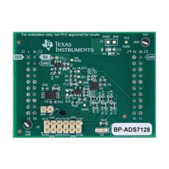
Page 4: Bp-Ads7128Evm Overview
(GPIOs), digital interface, and provide power supply to the BP-ADS7128. Figure 2 shows a BP-ADS7128 overview. Figure 2. BP-ADS7128 Top Level Overview BP-ADS7128 BoosterPack™ Plug-In Module SBAU331 – May 2019 Submit Documentation Feedback Copyright © 2019, Texas Instruments Incorporated... - Page 5 MSP-EXP432E401Y is used to supply 3.3 V to DVDD and to AVDD through a low-dropout (LDO) regulator, the TPS78001, on the BP-ADS7128. There is an onboard option to use an external power supply for DVDD. SBAU331 – May 2019 BP-ADS7128 BoosterPack™ Plug-In Module Submit Documentation Feedback Copyright © 2019, Texas Instruments Incorporated...
-
Page 6: Bp-Ads7128 Evm Initial Setup
Firefox™ or Chrome™ and the TI Cloud Agent Application. Figure 3. Browser Extension and TI Cloud Agent Installation BP-ADS7128 BoosterPack™ Plug-In Module SBAU331 – May 2019 Submit Documentation Feedback Copyright © 2019, Texas Instruments Incorporated... -
Page 7: Msp432E401Y Launchpad™ 5V-Otg Jumper
1. On the MSP432E401Y LaunchPad™, remove jumper JP6 from its default position and place this jumper on the JP1 jumper, as shown in Figure 4, at location 5V-OTG. Figure 4. MSP432E401Y LaunchPad™ 5V-OTG Jumper SBAU331 – May 2019 BP-ADS7128 BoosterPack™ Plug-In Module Submit Documentation Feedback Copyright © 2019, Texas Instruments Incorporated... -
Page 8: Launchpad™ Debug Port
File menu option. This selection automatically recognizes the MSP432E401Y LaunchPad™ and FLASH program, see Figure 7, to communicate with the BP-ADS7128. Figure 6. UNIFLASH Programming Set-Up BP-ADS7128 BoosterPack™ Plug-In Module SBAU331 – May 2019 Submit Documentation Feedback Copyright © 2019, Texas Instruments Incorporated... -
Page 9: Flash Programming Launchpad
4. After programming and verification is successful, as shown in Figure 8, disconnect the USB from the MSP-EXP432E401Y debug port. Figure 8. Successful FLASH Program SBAU331 – May 2019 BP-ADS7128 BoosterPack™ Plug-In Module Submit Documentation Feedback Copyright © 2019, Texas Instruments Incorporated... -
Page 10: Bp-Ads7128 Stacked On The Msp432E401Y Launchpad
2. Connect the MSP-EXP432E401Y micro USB data port to an available USB port on the PC. Figure 9 shows the assembled BP-ADS7128 and MSP-EXP432E401Y configuration. Figure 9. BP-ADS7128 Stacked on the MSP432E401Y LaunchPad™ BP-ADS7128 BoosterPack™ Plug-In Module SBAU331 – May 2019 Submit Documentation Feedback Copyright © 2019, Texas Instruments Incorporated... -
Page 11: Ads7128 Gui Landing Page
GUI, there is an option to connect and disconnect the hardware from the GUI. Figure 10. ADS7128 GUI Landing Page SBAU331 – May 2019 BP-ADS7128 BoosterPack™ Plug-In Module Submit Documentation Feedback Copyright © 2019, Texas Instruments Incorporated... -
Page 12: Ads7128 Device Configuration Tab
ADC channels as analog input channels. TI recommends enabling this option to then disable the preferred ADC channels and configure the selected channels based on user preference. BP-ADS7128 BoosterPack™ Plug-In Module SBAU331 – May 2019 Submit Documentation Feedback Copyright © 2019, Texas Instruments Incorporated... -
Page 13: Channel Configuration Page, Input Channel Tab
Any digital input channel can be selected to trigger the ALERT pin when the selected state change occurs. Figure 12. Channel Configuration Page, Input Channel Tab SBAU331 – May 2019 BP-ADS7128 BoosterPack™ Plug-In Module Submit Documentation Feedback Copyright © 2019, Texas Instruments Incorporated... -
Page 14: Channel Configuration Page, Output Channels Tab
The device powers up in manual mode and can be configured into any of the functional modes by writing the configuration registers for the desired mode. BP-ADS7128 BoosterPack™ Plug-In Module SBAU331 – May 2019 Submit Documentation Feedback Copyright © 2019, Texas Instruments Incorporated... -
Page 15: Sampling Mode Configuration
The programmable blanking time can be disabled or enabled. Figure 15. Zero-Cross Detection Page SBAU331 – May 2019 BP-ADS7128 BoosterPack™ Plug-In Module Submit Documentation Feedback Copyright © 2019, Texas Instruments Incorporated... -
Page 16: Averager And Statistics Page
The statistic function can also be enabled or disable within this page. Figure 16. Averager and Statistics Page BP-ADS7128 BoosterPack™ Plug-In Module SBAU331 – May 2019 Submit Documentation Feedback Copyright © 2019, Texas Instruments Incorporated... -
Page 17: Ads7128 Rms Page
Based on the number of samples selected, the RMS is calculated using the final formula shown. Figure 17. ADS7128 RMS Page SBAU331 – May 2019 BP-ADS7128 BoosterPack™ Plug-In Module Submit Documentation Feedback Copyright © 2019, Texas Instruments Incorporated... -
Page 18: Ads7128 Data Capture Tab
Digital I/O: The enabled digital channels, input or output, are displayed in this page Section 3.3.5 for more information on capturing data. Figure 18. ADS7128 Data Capture Tab BP-ADS7128 BoosterPack™ Plug-In Module SBAU331 – May 2019 Submit Documentation Feedback Copyright © 2019, Texas Instruments Incorporated... -
Page 19: Ads7128 Register Map Page
When making changes, the bit being changed is highlighted in yellow. Figure 19. ADS7128 Register Map Page SBAU331 – May 2019 BP-ADS7128 BoosterPack™ Plug-In Module Submit Documentation Feedback Copyright © 2019, Texas Instruments Incorporated... -
Page 20: Data Capture Conversion Results
Figure 20. Data Capture Conversion Results BP-ADS7128 BoosterPack™ Plug-In Module SBAU331 – May 2019 Submit Documentation Feedback Copyright © 2019, Texas Instruments Incorporated... -
Page 21: Time Domain Channel Selection
Hysteresis (if configured), is also displayed within this graph as dashed red lines. Figure 22. Time Domain Display With Threshold and Hysteresis SBAU331 – May 2019 BP-ADS7128 BoosterPack™ Plug-In Module Submit Documentation Feedback Copyright © 2019, Texas Instruments Incorporated... -
Page 22: Histogram Graph Display With Threshold And Hysteresis
The high and low threshold levels and the configured hysteresis are also displayed in the histogram graph. Figure 23. Histogram Graph Display With Threshold and Hysteresis BP-ADS7128 BoosterPack™ Plug-In Module SBAU331 – May 2019 Submit Documentation Feedback Copyright © 2019, Texas Instruments Incorporated... -
Page 23: Alarm Triggered
ALARM section where the corresponding image to the threshold crossed, high or low, turns red when triggered. The alarm can be cleared by clicking on the red icon. Figure 24. Alarm Triggered SBAU331 – May 2019 BP-ADS7128 BoosterPack™ Plug-In Module Submit Documentation Feedback Copyright © 2019, Texas Instruments Incorporated... -
Page 24: Input Signal-Conditioning Block On The Bp-Ads7128
The board has a provision to bypass the operational amplifier (U4) based on the signal conditioning requirement. In order to bypass this block, remove the R25 0-Ω resistor and populate R10. See Section 5.3 for more details. BP-ADS7128 BoosterPack™ Plug-In Module SBAU331 – May 2019 Submit Documentation Feedback Copyright © 2019, Texas Instruments Incorporated... -
Page 25: Bill Of Materials, Printed Circuit Board Layout, And Schematics
RTE0016C_WF (WQFN-16) I2C BUS EEPROM (2-Wire), TSSOP-B8 BR24G32FVT-3AGE2 Texas Instruments 10-MHz, RRIO, CMOS Operational Amplifier for Cost-Sensitive Systems, TLV9061IDBVR Texas Instruments DBV0005A (SOT-23-5) SBAU331 – May 2019 BP-ADS7128 BoosterPack™ Plug-In Module Submit Documentation Feedback Copyright © 2019, Texas Instruments Incorporated... -
Page 26: Bp_Ads7128 Pcb Top Overlay
Bill of Materials, Printed Circuit Board Layout, and Schematics www.ti.com PCB Layout Figure Figure Figure 28, and Figure 29 illustrate the EVM PCB layout. Figure 26. BP_ADS7128 PCB Top Overlay BP-ADS7128 BoosterPack™ Plug-In Module SBAU331 – May 2019 Submit Documentation Feedback Copyright © 2019, Texas Instruments Incorporated... -
Page 27: Bp-Ads7128 Top Layer Copper And Silkscreen
Bill of Materials, Printed Circuit Board Layout, and Schematics www.ti.com Figure 27. BP-ADS7128 Top Layer Copper and Silkscreen SBAU331 – May 2019 BP-ADS7128 BoosterPack™ Plug-In Module Submit Documentation Feedback Copyright © 2019, Texas Instruments Incorporated... -
Page 28: Bp-Ads7128 Bottom Layer Copper And Silkscreen
Bill of Materials, Printed Circuit Board Layout, and Schematics www.ti.com Figure 28. BP-ADS7128 Bottom Layer Copper and Silkscreen BP-ADS7128 BoosterPack™ Plug-In Module SBAU331 – May 2019 Submit Documentation Feedback Copyright © 2019, Texas Instruments Incorporated... - Page 29 Bill of Materials, Printed Circuit Board Layout, and Schematics www.ti.com Figure 29. BP-ADS7128 Power Plane Layer Schematics Figure 30 illustrates the ADS7128 BoosterPack™ schematics. SBAU331 – May 2019 BP-ADS7128 BoosterPack™ Plug-In Module Submit Documentation Feedback Copyright © 2019, Texas Instruments Incorporated...
- Page 30 Bill of Materials, Printed Circuit Board Layout, and Schematics www.ti.com Figure 30. ADS7128 BoosterPack™ Schematic Diagram BP-ADS7128 BoosterPack™ Plug-In Module SBAU331 – May 2019 Submit Documentation Feedback Copyright © 2019, Texas Instruments Incorporated...
- Page 31 TI products. TI’s provision of these resources does not expand or otherwise alter TI’s applicable warranties or warranty disclaimers for TI products. Mailing Address: Texas Instruments, Post Office Box 655303, Dallas, Texas 75265 Copyright © 2019, Texas Instruments Incorporated...
Need help?
Do you have a question about the BoosterPack BP-ADS7128 and is the answer not in the manual?
Questions and answers