Table of Contents
Advertisement
Quick Links
ADS5296, 4-Channel 200-MSPS, and 8-Channel 80-MSPS,
Analog-to-Digital Converter Evaluation Module
This user's guide gives a general overview of the ADS5296 evaluation module (EVM) and provides a
general description of the features and functions to be considered while using this module. This manual is
applicable to the ADS5296 analog-to-digital converters (ADC). The ADS5296 EVM provides a platform for
evaluating the ADC under various signal, clock, reference, and ADC output formats.
1
2
2.1
2.2
3
3.1
3.2
3.3
4
4.1
4.2
4.3
4.4
5
5.1
5.2
5.3
5.4
5.5
6
7
8
1
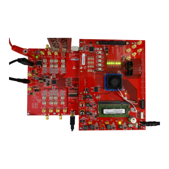
Evaluation Setup
2
HSDCpro Install (a)
3
HSDCpro Install (b)
4
HSDCpro Install (c)
5
HSDCpro Install (d)
6
HSDCpro Install (e)
7
HSDCpro Install (f)
8
HSDCpro Install (g)
9
HSDCpro Install (h)
10
HSDCpro Install (i)
11
ADS5296 GUI Install (a)
12
ADS5296 GUI Install (b)
13
ADS5296 GUI Install (c)
SLAU491 - May 2013
Submit Documentation Feedback
...........................................................................................
..................................................................................................
................................................................................
............................................................................................
...................................................................................................
...........................................................................
................................................................................
...................................................................................................
...............................................................................................
.....................................................................................................
..................................................................................................
...................................................................................
................................................................................................
..............................................................................................
..........................................................................................
....................................................................................................
List of Figures
............................................................................................................
.........................................................................................................
.........................................................................................................
.........................................................................................................
.........................................................................................................
.........................................................................................................
........................................................................................................
.......................................................................................................
.......................................................................................................
........................................................................................................
..................................................................................................
..................................................................................................
..................................................................................................
ADS5296, 4-Channel 200-MSPS, and 8-Channel 80-MSPS, Analog-to-Digital
Copyright © 2013, Texas Instruments Incorporated
Contents
.....................................................................
.........................................................................
....................................................................
................................................
......................................................
User's Guide
SLAU491 - May 2013
..........................
Converter Evaluation Module
4
5
5
11
18
18
19
21
24
24
29
34
45
50
52
53
57
59
61
67
76
78
4
5
6
7
8
9
10
10
11
11
12
13
14
1
Advertisement
Table of Contents

Related Manuals for Texas Instruments ADS5296


Summary of Contents for Texas Instruments ADS5296
-
Page 1: Table Of Contents
ADS5296, 4-Channel 200-MSPS, and 8-Channel 80-MSPS, Analog-to-Digital Converter Evaluation Module This user’s guide gives a general overview of the ADS5296 evaluation module (EVM) and provides a general description of the features and functions to be considered while using this module. This manual is applicable to the ADS5296 analog-to-digital converters (ADC). - Page 2 ADS5296 GUI Install (g) ..................TSW1400 and ADS5296 Setup ................. ADS5296 EVM Default Header Configuration ..........ADS5296 EVM Octal Non-Interleaving Mode Analog Input SMAs ............ADS5296 EVM Quad Interleaving Mode Analog Input SMAs ....................TSW1400 GUI Setup (a) ....................TSW1400 GUI Setup (b) ....................
- Page 3 ..................ADS5296 Schematic, Sheet 8 of 9 ..................ADS5296 Schematic, Sheet 9 of 9 ............ADS5296 EVM Top Layer Assembly Drawing – Top View ..........ADS5296 EVM Bottom Layer Assembly Drawing – Bottom View ....................ADS5296 EVM Top Side ...................
-
Page 4: Quick View Of Evaluation Setup
Power Supply: A single +5-V supply powers the ADS5296 EVM through connectors located at J1 and J2. The supply for the ADS5296 device is derived from this +5 V supply. The power supply must be able to source up to 1.5 A. The TSW1400 EVM is powered through an AC adaptor provided with its EVM kit. -
Page 5: Gui Software Installation
GUI Software Installation The ADS5296 EVM and the TSW1400 EVM both require software installations. The following two sections explain where to find and how to install the software properly. Ensure that no USB connections are made to the EVMs until after the installations are complete. - Page 6 GUI Software Installation www.ti.com Figure 3. HSDCpro Install (b) • Read the License Agreement from Texas Instruments and select I accept the License Agreement and press the Next button as shown in Figure ADS5296, 4-Channel 200-MSPS, and 8-Channel 80-MSPS, Analog-to-Digital SLAU491 –...
- Page 7 Read the License Agreement from National Instruments and select I accept the License Agreement and press the Next button as in Figure SLAU491 – May 2013 ADS5296, 4-Channel 200-MSPS, and 8-Channel 80-MSPS, Analog-to-Digital Converter Evaluation Module Submit Documentation Feedback Copyright © 2013, Texas Instruments Incorporated...
- Page 8 GUI Software Installation www.ti.com Figure 5. HSDCpro Install (d) • Press the Next button as shown in Figure ADS5296, 4-Channel 200-MSPS, and 8-Channel 80-MSPS, Analog-to-Digital SLAU491 – May 2013 Converter Evaluation Module Submit Documentation Feedback Copyright © 2013, Texas Instruments Incorporated...
- Page 9 Figure 6. HSDCpro Install (e) • The window shown in Figure 7 should appear, indicating that installation is in progress. SLAU491 – May 2013 ADS5296, 4-Channel 200-MSPS, and 8-Channel 80-MSPS, Analog-to-Digital Converter Evaluation Module Submit Documentation Feedback Copyright © 2013, Texas Instruments Incorporated...
- Page 10 Figure 8. HSDCpro Install (g) • The window in Figure 9 appears briefly to complete the process. ADS5296, 4-Channel 200-MSPS, and 8-Channel 80-MSPS, Analog-to-Digital SLAU491 – May 2013 Converter Evaluation Module Submit Documentation Feedback Copyright © 2013, Texas Instruments Incorporated...
-
Page 11: Ads5296 Evm Gui Installation
ADS5295_96 during the installation exist. From the Texas Instruments website, www.ti.com, search for ADS5296 EVM. Clicking on the hyperlink in the table will lead to another link titled ADS5295 and ADS5296 GUI Installer, v2.1 (Rev. B). Click on this link to download and save the zipped file (slac547b.zip). - Page 12 • Set the destination directories for the ADS5295_96 GUI installation or leave as default and press the Next button as shown in Figure ADS5296, 4-Channel 200-MSPS, and 8-Channel 80-MSPS, Analog-to-Digital SLAU491 – May 2013 Converter Evaluation Module Submit Documentation Feedback...
- Page 13 GUI Software Installation www.ti.com Figure 12. ADS5296 GUI Install (b) • Read the License Agreement from Texas Instruments and select the I accept the License Agreement button and then press the Next button as shown in Figure SLAU491 – May 2013...
- Page 14 Read the License Agreement from National Instruments and select the I accept the License Agreement button and then press the Next button as shown in Figure ADS5296, 4-Channel 200-MSPS, and 8-Channel 80-MSPS, Analog-to-Digital SLAU491 – May 2013 Converter Evaluation Module Submit Documentation Feedback Copyright ©...
-
Page 15: Ads5296 Gui Install (D)
Figure 14. ADS5296 GUI Install (d) • To begin the installation, press the Next button as shown in Figure SLAU491 – May 2013 ADS5296, 4-Channel 200-MSPS, and 8-Channel 80-MSPS, Analog-to-Digital Converter Evaluation Module Submit Documentation Feedback Copyright © 2013, Texas Instruments Incorporated... -
Page 16: Ads5296 Gui Install (E)
Figure 15. ADS5296 GUI Install (e) • The window shown in Figure 16 should appear showing that installation is in progress. ADS5296, 4-Channel 200-MSPS, and 8-Channel 80-MSPS, Analog-to-Digital SLAU491 – May 2013 Converter Evaluation Module Submit Documentation Feedback Copyright © 2013, Texas Instruments Incorporated... -
Page 17: Ads5296 Gui Install (F)
• Upon complete of installation, the window in Figure 17 appears. Press the Finish button to continue. SLAU491 – May 2013 ADS5296, 4-Channel 200-MSPS, and 8-Channel 80-MSPS, Analog-to-Digital Converter Evaluation Module Submit Documentation Feedback Copyright © 2013, Texas Instruments Incorporated... -
Page 18: Hardware And Evm Setup For Testing Ads5296
ADS5296 EVM and the TSW1400 EVM can be performed using a RAMP function generated within the ADS5296 device in lieu of the signal source listed in item 7 below. Also, an on-board 80-MHz crystal oscillator (XTAL) can provide the ADC sampling clock in lieu of the signal source listed in item 6 below. -
Page 19: Ads5296 Evm Header Configuration
Figure 18. TSW1400 and ADS5296 Setup 1. Mate the TSW1400 EVM at connector J3 to the ADS5296 EVM at connector J8 through the high speed ADC interface connector. 2. Connect the DC +5-V output of the provided AC-to-DC power supply to J12 (+5V_IN) of the TSW1400 EVM and the input of the power supply cable to a 110–230 VAC source. -
Page 20: Ads5296 Evm Header Configuration
Hardware and EVM Setup for Testing ADS5296 www.ti.com Table 1. ADS5296 EVM Header Configuration Jumper Default Config Pin 1 Pin 3 Circuit Description Silkscreen Silkscreen short pins 1-2 1.8V_AVDD +3.3V Power Supply Power Supply for DUT: ALWAYS 1.8V_AVDD short pins 2-3 CDC_3.3V... -
Page 21: Ads5296 Evm 0-Ω Jumper Configuration
The ADS5296 can be used an Octal-channel non-interleaving ADC or as a Quad-channel interleaving ADC. The ADS5296 EVM is delivered in a configuration that allows testing both modes without any changes required by the user, except through the software GUI. -
Page 22: Ads5296 Evm Octal Non-Interleaving Mode Analog Input Smas
Hardware and EVM Setup for Testing ADS5296 www.ti.com The ADS5296 EVM has eight SMAs vertically mounted on the topside of the board corresponding to eight analog input channels labeled CHx_XFMR, where x = 1 to 8, as shown in colored boxes of... -
Page 23: Ads5296 Evm Quad Interleaving Mode Analog Input Smas
R346, R348, R368, and R370, respectively. When an input signal is provided SMA J27, CH1_AMP(1,2), a switch internal to the ADS5296, selects whether ADC channel 1 or ADC channel 2 is sampled. The selection depends on the state of GUI control ODD_EVEN_SEL or on the position of header JP2. -
Page 24: Testing Ads5296 Evm
Capturing a Sinusoidal Input in Quad Interleaving Mode Only the minimal software GUI settings required to achieve the above tests will be described in this section. For a detailed explanation of the ADS5296 software GUI and all its features, please see Section 5. - Page 25 2. Select a device by clicking on the Blue arrow in the upper left corner of the HSDCpro GUI. Scroll down and select ADS5296 as shown in Figure SLAU491 – May 2013 ADS5296, 4-Channel 200-MSPS, and 8-Channel 80-MSPS, Analog-to-Digital Converter Evaluation Module Submit Documentation Feedback Copyright © 2013, Texas Instruments Incorporated...
- Page 26 Figure 27 will appear. Figure 27. TSW1400 GUI Setup (f) Once loaded, the plug-in ADS5296 GUI will appear as a new tab within the HSDCpro GUI as shown in Figure ADS5296, 4-Channel 200-MSPS, and 8-Channel 80-MSPS, Analog-to-Digital SLAU491 – May 2013...
-
Page 27: Ads5296 Plug-In Gui Setup (A)
Figure 28. ADS5296 Plug-in GUI Setup (a) 3. Click on the tab ADS5296 GUI to view the software GUI for the ADS5296. The GUI consists of two tabs: Read Me First and High Level Test as shown in Figure SLAU491 –... -
Page 28: Ads5296 Plug-In Gui Setup (B)
Testing ADS5296 EVM www.ti.com Figure 29. ADS5296 Plug-in GUI Setup (b) Clicking on the High Level Test tab shows four sub-tabs: Top Level, Test Pattern, Digital Signal Processing, and Channel Filter as shown in Figure ADS5296, 4-Channel 200-MSPS, and 8-Channel 80-MSPS, Analog-to-Digital SLAU491 –... -
Page 29: Capturing A Ramp Test Pattern
+5-V power supply current drop from ~850 mA to ~563 mA. If the DC current is approximately 600 mA with both power down boxes unchecked, it indicates that the ADS5296 is not receiving the sampling clock. Please ensure that the 3-pin headers are configured as described in Section 3.2. -
Page 30: Ads5296 Gui Setup For Ramp Test
Testing ADS5296 EVM www.ti.com Figure 31. ADS5296 GUI Setup for RAMP Test 2. Perform the following steps highlighted in Figure (a) Press the ADC tab in HSDCpro (b) Change the plot type from Real FFT to Codes (c) Enter 80M in the field labeled ADC Output Data Rate... -
Page 31: Hsdcpro Gui Setup For Ramp Test
Figure 32. HSDCpro GUI Setup for RAMP Test 3. The saw tooth waveform should be captured and displayed as in Figure SLAU491 – May 2013 ADS5296, 4-Channel 200-MSPS, and 8-Channel 80-MSPS, Analog-to-Digital Converter Evaluation Module Submit Documentation Feedback Copyright © 2013, Texas Instruments Incorporated... -
Page 32: Ramp Capture
8 channels and confirm that a saw tooth waveform has been captured. Also confirm, in the menu to the left side, that the min code is 0 and the max code is 4095, corresponding to a 12-bit ADC. ADS5296, 4-Channel 200-MSPS, and 8-Channel 80-MSPS, Analog-to-Digital SLAU491 – May 2013... -
Page 33: Ramp Capture By Channel
35, is recommended to ensure that the RAMP waveform increments 1 ADC code for each subsequent sample. SLAU491 – May 2013 ADS5296, 4-Channel 200-MSPS, and 8-Channel 80-MSPS, Analog-to-Digital Converter Evaluation Module Submit Documentation Feedback Copyright © 2013, Texas Instruments Incorporated... -
Page 34: Capturing Sinusoidal Input In Octal Non-Interleaving Mode
Capturing Sinusoidal Input in Octal Non-Interleaving Mode This section describes the necessary steps to reconfigure the EVM and test setup for capturing a sinusoidal input with the ADS5296 in octal non-interleaving mode. 1. The RAMP test described in Section 4.2 was performed using an 80-MHz on-board crystal oscillator (XTAL) for the sampling clock. -
Page 35: Jumper J35 And J38 Positions For Enabled Xtal (Default)
Testing ADS5296 EVM www.ti.com Figure 36. Jumper J35 and J38 positions for Enabled XTAL (default) SLAU491 – May 2013 ADS5296, 4-Channel 200-MSPS, and 8-Channel 80-MSPS, Analog-to-Digital Converter Evaluation Module Submit Documentation Feedback Copyright © 2013, Texas Instruments Incorporated... -
Page 36: Jumper J35 And J38 Positions For Disabled Xtal
This is achieved connecting the two via a BNC cable. One instrument will provide 10- MHz output while the other instrument will receive 10-MHz input. ADS5296, 4-Channel 200-MSPS, and 8-Channel 80-MSPS, Analog-to-Digital SLAU491 – May 2013 Converter Evaluation Module Submit Documentation Feedback Copyright ©... -
Page 37: Octal Non-Interleaving Mode Hardware Setup
Testing ADS5296 EVM www.ti.com Figure 38. Octal Non-interleaving Mode Hardware Setup 3. Click on ADS5296 GUI tab and ensure that the TEST_PATT field is set to None, as shown in Figure SLAU491 – May 2013 ADS5296, 4-Channel 200-MSPS, and 8-Channel 80-MSPS, Analog-to-Digital... -
Page 38: Ads5296 Gui Setup For Octal Non-Interleaving Mode
Testing ADS5296 EVM www.ti.com Figure 39. ADS5296 GUI Setup for Octal Non-Interleaving Mode 4. Click on the ADC tab and perform the following steps as illustrated in Figure (a) In the box labeled ADC Input Target Frequency input 10M (b) In the drop down menus set Real FFT, Channel 5/8, Rectangular... -
Page 39: Hsdcpro Gui Setup For Octal Non-Interleaving Mode (B)
In the example shown here, the input level should be changed from 15.0 dBm to 15.1 dBm and then a capture retaken. SLAU491 – May 2013 ADS5296, 4-Channel 200-MSPS, and 8-Channel 80-MSPS, Analog-to-Digital Converter Evaluation Module Submit Documentation Feedback... - Page 40 Figure 41. Octal Non-Interleaving Mode Capture 1 6. After re-capturing, the Fund. value is now closer to –1.0 dBFs as shown in Figure ADS5296, 4-Channel 200-MSPS, and 8-Channel 80-MSPS, Analog-to-Digital SLAU491 – May 2013 Converter Evaluation Module Submit Documentation Feedback...
- Page 41 10-MHz input signal. A 4.5 dB difference in the computed SNR is observed and is attributed solely to the integrity of the input signal, specifically the close-in phase noise. SLAU491 – May 2013 ADS5296, 4-Channel 200-MSPS, and 8-Channel 80-MSPS, Analog-to-Digital Converter Evaluation Module Submit Documentation Feedback...
- Page 42 A software filter can be used to remove the contribution of phase noise using the HSDCpro menu Test Options => Frequency Bins as shown in Figure ADS5296, 4-Channel 200-MSPS, and 8-Channel 80-MSPS, Analog-to-Digital SLAU491 – May 2013 Converter Evaluation Module Submit Documentation Feedback Copyright ©...
- Page 43 Figure 44. HSDCpro Software Filtering Change the default values from 0 to 500 as shown in Figure SLAU491 – May 2013 ADS5296, 4-Channel 200-MSPS, and 8-Channel 80-MSPS, Analog-to-Digital Converter Evaluation Module Submit Documentation Feedback Copyright © 2013, Texas Instruments Incorporated...
- Page 44 The SNR is now very close to the Software Filtering Menu SNR shown in Figure 43 using a superior instrument. ADS5296, 4-Channel 200-MSPS, and 8-Channel 80-MSPS, Analog-to-Digital SLAU491 – May 2013 Converter Evaluation Module Submit Documentation Feedback Copyright © 2013, Texas Instruments Incorporated...
-
Page 45: Capturing Sinusoidal Input In Quad Interleaving Mode
Capturing Sinusoidal Input in Quad Interleaving Mode This section describes the necessary steps to reconfigure the EVM and test setup for capturing a sinusoidal input with the ADS5296 in quad interleaving mode. 1. Setup the EVM as shown in Figure 47... - Page 46 2. From the ADS5296 GUI, Top Level tab, make the following changes as shown in Figure 48. With this configuration the ADS5296 will be sampling channel 1 since the ODD_EVEN_SEL is set to ODD in the software GUI. (a) Change EN_BIT_SER to 10-bits...
- Page 47 Figure 48. Quad-Interleaving Mode GUI Setup Figure 49 shows that the Fund. value is ~0.8 dB low. SLAU491 – May 2013 ADS5296, 4-Channel 200-MSPS, and 8-Channel 80-MSPS, Analog-to-Digital Converter Evaluation Module Submit Documentation Feedback Copyright © 2013, Texas Instruments Incorporated...
- Page 48 Figure 49. Quad-Interleaving Mode Capture 1 Increasing the output power from the signal generator by +0.8 dB and re-capturing results in Figure ADS5296, 4-Channel 200-MSPS, and 8-Channel 80-MSPS, Analog-to-Digital SLAU491 – May 2013 Converter Evaluation Module Submit Documentation Feedback...
- Page 49 HSDCpro GUI auto-calculates the location of this spur in the menu Test Options → Notch Frequency Bins and allows for removal this bin from the plot if desired as shown in Figure SLAU491 – May 2013 ADS5296, 4-Channel 200-MSPS, and 8-Channel 80-MSPS, Analog-to-Digital Converter Evaluation Module Submit Documentation Feedback Copyright © 2013, Texas Instruments Incorporated...
-
Page 50: Ads5296 Gui In Detail
Filter. After launching HSDCpro, the ADS5296 GUI can be invoked in two ways: normal mode or simulation mode. Simulation mode is used in the event that no ADS5296 EVM is available. When this is the case, the message shown in Figure 52 appears shortly after choosing the ADS5296 device in HSDCpro. - Page 51 The user is given the choice to Continue in Simulation or Stop & Close. If Continue in Simulation is selected the ADS5296 GUI will install and all controls will “appear” to function as normal including the DIGITAL WAVEFORM GRAPH-WRITE which shows what is being written to the serial interface. When in...
-
Page 52: Read Me First Tab
55, there are nine sequences pre-defined in this folder corresponding to the nine OPERATING MODES OF ADS5296 shown in the table at the bottom of the tab. The table includes the maximum sampling clock speed supported for each mode. Ensure that the clock source is within this limit for a particular mode. -
Page 53: Top Level Tab
POWERDOWN MODES, CUSTOM WRITE/READ and DEVICE PIN CONTROL. In the right border of this tab is a section called DIGITAL WAVEFORM GRAPH-WRITE. SLAU491 – May 2013 ADS5296, 4-Channel 200-MSPS, and 8-Channel 80-MSPS, Analog-to-Digital Converter Evaluation Module Submit Documentation Feedback Copyright © 2013, Texas Instruments Incorporated... - Page 54 ADC. The button to the right of this menu, and seen throughout the GUI, is an info button and displays relevant information from the datasheet. ADS5296, 4-Channel 200-MSPS, and 8-Channel 80-MSPS, Analog-to-Digital SLAU491 – May 2013...
- Page 55 When the info button next the EN_SER_BIT control is selected with 12-bits selected the information shown in Figure 59 is presented. SLAU491 – May 2013 ADS5296, 4-Channel 200-MSPS, and 8-Channel 80-MSPS, Analog-to-Digital Converter Evaluation Module Submit Documentation Feedback Copyright © 2013, Texas Instruments Incorporated...
- Page 56 The button EN_HIGH_ADDR is required to enable the EN_EXT_REF button below it. This dependency represents the implementation in the design itself. The ADS5296 device supports both internal and external reference mode to set the full-scale of the ADC. The EN_INTERLEAVE button is used to enable and disable the interleaving mode, thus, switching the device between a quad channel ADC and an octal ADC, respectively.
-
Page 57: Test Pattern Tab
The CUSTOM WRITE/READ section of the Top Level tab allows for custom writing to the serial interface of the ADS5296 as well as reading back register values. When a valid register address and value is provided the corresponding control will automatically update to reflect the current state of the device. In... -
Page 58: Prbs Section Enabled
The TEST PATTERN MODES section contains commonly used test patterns under the TEST_PATT drop- down menu as shown in Figure 64. All of these patterns are generated internal to the ADS5296 device and provided on all channels simultaneously. ADS5296, 4-Channel 200-MSPS, and 8-Channel 80-MSPS, Analog-to-Digital SLAU491 –... -
Page 59: Digital Signal Processing Tab
CHANNEL_GAIN, LOW FREQUENCY NOISE SUPPRESSION, SWAP ANALOG INPUTS, and INPUT/OUTPUT MAPPING. Figure 65. Digital Signal Processing Tab SLAU491 – May 2013 ADS5296, 4-Channel 200-MSPS, and 8-Channel 80-MSPS, Analog-to-Digital Converter Evaluation Module Submit Documentation Feedback Copyright © 2013, Texas Instruments Incorporated... -
Page 60: Channel Averaging Info Button
Not shown in the table are the two other options appearing the GUI drop-down menus, ZERO and ADC CHx, which represents the actual design implementation.) Figure 67. Channel Averaging Info Button ADS5296, 4-Channel 200-MSPS, and 8-Channel 80-MSPS, Analog-to-Digital SLAU491 – May 2013 Converter Evaluation Module Submit Documentation Feedback Copyright ©... -
Page 61: Channel Filter Tab
As shown in Figure 70, the controls have interdependencies, reflecting the actual silicon implementation. SLAU491 – May 2013 ADS5296, 4-Channel 200-MSPS, and 8-Channel 80-MSPS, Analog-to-Digital Converter Evaluation Module Submit Documentation Feedback Copyright © 2013, Texas Instruments Incorporated... - Page 62 Figure 70. Channel Filter Tab Checking the EN_DIG_FILTER box causes the USE_FILTER control to become un-greyed and enabled for all eight channels as shown in Figure ADS5296, 4-Channel 200-MSPS, and 8-Channel 80-MSPS, Analog-to-Digital SLAU491 – May 2013 Converter Evaluation Module Submit Documentation Feedback...
-
Page 63: Dig_Filter
To invoke this block the USE_FILTER box must be checked, thus, enabling all controls associated with the digital and decimation filters as shown in Figure SLAU491 – May 2013 ADS5296, 4-Channel 200-MSPS, and 8-Channel 80-MSPS, Analog-to-Digital Converter Evaluation Module Submit Documentation Feedback Copyright © 2013, Texas Instruments Incorporated... -
Page 64: Channel 1 Digital Filter Enabled
75. In addition, the graphs of the pre-stored filters are replaced with the twelve registers that hold the twelve, 12-bit, signed coefficients for one custom filter. ADS5296, 4-Channel 200-MSPS, and 8-Channel 80-MSPS, Analog-to-Digital SLAU491 – May 2013 Converter Evaluation Module Submit Documentation Feedback Copyright ©... -
Page 65: Channel 1 Custom Digital Filter Enabled
77, can be used to save the currently displayed channel’s custom coefficients to a file or all channels’ custom coefficients to a file. SLAU491 – May 2013 ADS5296, 4-Channel 200-MSPS, and 8-Channel 80-MSPS, Analog-to-Digital Converter Evaluation Module Submit Documentation Feedback... -
Page 66: Save/Load Custom Filter Coeffs On Channel Filter Tab
Figure 78. Only those channels whose USE_FILTER bit are enabled are active, and thus, available for viewing. Figure 78. View Filter Coeffs ADS5296, 4-Channel 200-MSPS, and 8-Channel 80-MSPS, Analog-to-Digital SLAU491 – May 2013 Converter Evaluation Module Submit Documentation Feedback Copyright © 2013, Texas Instruments Incorporated... -
Page 67: Ads5296 Evm Schematics
OUT1N OUT8P J8B_111_ADCRESET 10K Ohm J8B_113_SDOUT J8B_115_CSZ J8B_117_SDATA J8B_119_SCLK Figure 79. ADS5296 Schematic, Sheet 1 of 9 SLAU491 – May 2013 ADS5296, 4-Channel 200-MSPS, and 8-Channel 80-MSPS, Analog-to-Digital Converter Evaluation Module Submit Documentation Feedback Copyright © 2013, Texas Instruments Incorporated... -
Page 68: Ads5296 Schematic, Sheet 2 Of
0 ohm R188 R183 0 ohm 0 ohm EP_GND CDCLVP1102 Figure 80. ADS5296 Schematic, Sheet 2 of 9 ADS5296, 4-Channel 200-MSPS, and 8-Channel 80-MSPS, Analog-to-Digital SLAU491 – May 2013 Converter Evaluation Module Submit Documentation Feedback Copyright © 2013, Texas Instruments Incorporated... -
Page 69: Ads5296 Schematic, Sheet 3 Of
0 ohm 0 ohm 10 ohm 10 ohm 0.1uF 0.1uF Figure 81. ADS5296 Schematic, Sheet 3 of 9 SLAU491 – May 2013 ADS5296, 4-Channel 200-MSPS, and 8-Channel 80-MSPS, Analog-to-Digital Converter Evaluation Module Submit Documentation Feedback Copyright © 2013, Texas Instruments Incorporated... -
Page 70: Ads5296 Schematic, Sheet 4 Of
0Ohm IN6_P IN8_P 10 ohm 10 ohm 0.1uF 0.1uF Figure 82. ADS5296 Schematic, Sheet 4 of 9 ADS5296, 4-Channel 200-MSPS, and 8-Channel 80-MSPS, Analog-to-Digital SLAU491 – May 2013 Converter Evaluation Module Submit Documentation Feedback Copyright © 2013, Texas Instruments Incorporated... -
Page 71: Ads5296 Schematic, Sheet 5 Of
24.9 Ohm C193 C192 R310 0.1uF 0.1uF 0 ohm Figure 83. ADS5296 Schematic, Sheet 5 of 9 SLAU491 – May 2013 ADS5296, 4-Channel 200-MSPS, and 8-Channel 80-MSPS, Analog-to-Digital Converter Evaluation Module Submit Documentation Feedback Copyright © 2013, Texas Instruments Incorporated... -
Page 72: Ads5296 Schematic, Sheet 6 Of
250 ohm C221 0.1uF C220 R354 0.1uF 0 ohm Figure 84. ADS5296 Schematic, Sheet 6 of 9 ADS5296, 4-Channel 200-MSPS, and 8-Channel 80-MSPS, Analog-to-Digital SLAU491 – May 2013 Converter Evaluation Module Submit Documentation Feedback Copyright © 2013, Texas Instruments Incorporated... -
Page 73: Ads5296 Schematic, Sheet 7 Of
R108 0 ohm 5.1 ohm 0 ohm U31D 0.1uF Figure 85. ADS5296 Schematic, Sheet 7 of 9 SLAU491 – May 2013 ADS5296, 4-Channel 200-MSPS, and 8-Channel 80-MSPS, Analog-to-Digital Converter Evaluation Module Submit Documentation Feedback Copyright © 2013, Texas Instruments Incorporated... -
Page 74: Ads5296 Schematic, Sheet 8 Of
56.2K Ohm 10UF CDC_3.3V RESET 10UF OUT1 0.1uF 10UF Figure 86. ADS5296 Schematic, Sheet 8 of 9 ADS5296, 4-Channel 200-MSPS, and 8-Channel 80-MSPS, Analog-to-Digital SLAU491 – May 2013 Converter Evaluation Module Submit Documentation Feedback Copyright © 2013, Texas Instruments Incorporated... -
Page 75: Ads5296 Schematic, Sheet 9 Of
TP35 0Ohm 0Ohm TP20 DEFAULT: SHORT 1 & 2 Figure 87. ADS5296 Schematic, Sheet 9 of 9 SLAU491 – May 2013 ADS5296, 4-Channel 200-MSPS, and 8-Channel 80-MSPS, Analog-to-Digital Converter Evaluation Module Submit Documentation Feedback Copyright © 2013, Texas Instruments Incorporated... -
Page 76: Ads5296 Evm Bill Of Materials
ADS5296 EVM Bill of Materials www.ti.com ADS5296 EVM Bill of Materials Table 2. ADS5296 EVM Bill of Materials Reference Designator Value Manufacturer Part Number Description C1, C3, C5, C25, C29, C42, C102, C230 10UF TAJB106K016RNJ CAP TANT 10UF 16V 10% 1210 C10, C11, C12, C18, C20, C26, C27, C28, C30, C41, C43, C44, C45, C46, C49, C50, C59, 0.1uF... -
Page 77: Ads5296 Evm Bill Of Materials
ADS5296 EVM Bill of Materials www.ti.com Table 2. ADS5296 EVM Bill of Materials (continued) Reference Designator Value Manufacturer Part Number Description R100, R106 5.1 ohm VISHAY CRCW06035R10FKEA RES 5.10 OHM 1/10W 1% 0603 SMD R101, R107 1K OHM TYCO ELECTRONICS CRG0603F1K0 RES 1.00K OHM 1/10W 1% 0603... -
Page 78: Ads5296 Evm Layout
Figure 88 through Figure 93 illustrate the PCB layouts for the EVM. Figure 88. ADS5296 EVM Top Layer Assembly Drawing – Top View ADS5296, 4-Channel 200-MSPS, and 8-Channel 80-MSPS, Analog-to-Digital SLAU491 – May 2013 Converter Evaluation Module Submit Documentation Feedback... -
Page 79: Ads5296 Evm Bottom Layer Assembly Drawing - Bottom View
ADS5296 EVM Layout www.ti.com Figure 89. ADS5296 EVM Bottom Layer Assembly Drawing – Bottom View SLAU491 – May 2013 ADS5296, 4-Channel 200-MSPS, and 8-Channel 80-MSPS, Analog-to-Digital Converter Evaluation Module Submit Documentation Feedback Copyright © 2013, Texas Instruments Incorporated... -
Page 80: Ads5296 Evm Top Side
ADS5296 EVM Layout www.ti.com Figure 90. ADS5296 EVM Top Side ADS5296, 4-Channel 200-MSPS, and 8-Channel 80-MSPS, Analog-to-Digital SLAU491 – May 2013 Converter Evaluation Module Submit Documentation Feedback Copyright © 2013, Texas Instruments Incorporated... -
Page 81: Ads5296 Evm Ground Plane
ADS5296 EVM Layout www.ti.com Figure 91. ADS5296 EVM Ground Plane SLAU491 – May 2013 ADS5296, 4-Channel 200-MSPS, and 8-Channel 80-MSPS, Analog-to-Digital Converter Evaluation Module Submit Documentation Feedback Copyright © 2013, Texas Instruments Incorporated... -
Page 82: Ads5296 Evm Signal Plane
ADS5296 EVM Layout www.ti.com Figure 92. ADS5296 EVM Signal Plane ADS5296, 4-Channel 200-MSPS, and 8-Channel 80-MSPS, Analog-to-Digital SLAU491 – May 2013 Converter Evaluation Module Submit Documentation Feedback Copyright © 2013, Texas Instruments Incorporated... -
Page 83: Ads5296 Evm Bottom Side
ADS5296 EVM Layout www.ti.com Figure 93. ADS5296 EVM Bottom Side SLAU491 – May 2013 ADS5296, 4-Channel 200-MSPS, and 8-Channel 80-MSPS, Analog-to-Digital Converter Evaluation Module Submit Documentation Feedback Copyright © 2013, Texas Instruments Incorporated... - Page 84 IMPORTANT NOTICE Texas Instruments Incorporated and its subsidiaries (TI) reserve the right to make corrections, enhancements, improvements and other changes to its semiconductor products and services per JESD46, latest issue, and to discontinue any product or service per JESD48, latest issue.
Need help?
Do you have a question about the ADS5296 and is the answer not in the manual?
Questions and answers