Table of Contents
Advertisement
Quick Links
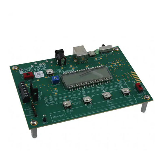
The ADS1131REF and the ADS1231REF are reference designs for delta-sigma analog-to-digital
converters (ADCs). The ADS1131REF contains the
contains the
ADS1231
needed for a weigh-scale digitizer, and are meant as examples of a good design for a basic weigh-scale
system. Each system is also suitable for general evaluation of the respectively installed ADC. Throughout
this document, the term ADS1x31REF is used to refer to the common features and functions for both
systems.
The ADS1x31REF hardware has the following features:
•
ADS1131 ADC for the ADS1131REF and ADS1231 ADC for the ADS1231REF
•
Connections for load cells or other voltage sources
•
Low-side excitation switch on the load cell header connector
•
Ample EMI/RFI suppression between the ADC and rest of design
•
Eight-digit starburst LCD readout
•
USB connection for firmware updates and remote control
•
Designed for very low power consumption
•
Battery (9V) or wall power
Version 1.0.0 of the firmware includes the following features:
•
Weigh-scale mode with two-point calibration
•
Complete configuration of the device
•
Real-time peak-to-peak and RMS noise calculation
•
Autoranging voltage display
•
Noise displayed in volts, codes, and bits
•
Voltage displayed in volts or codes
•
Adjustable averaging mode
•
Raw hexadecimal code display
•
Simple and fast configuration
•
Parameters saved to internal flash memory
•
Computer link
Graphical PC software is also provided for histogram display, datalogging, and device control.
We welcome bug reports and suggestions for additional features; please contact the Texas Instruments
Precision Analog Applications Group.
Hyperterm is a trademark of Microsoft Corporation.
Windows is a registered trademark of Microsoft Corporation.
All other trademarks are the property of their respective owners.
SBAU175A – July 2010 – Revised August 2011
Submit Documentation Feedback
ADS1131REF and ADS1231REF
24-bit device. Both systems contain all the circuitry and user interface elements
Copyright © 2010–2011, Texas Instruments Incorporated
SBAU175A – July 2010 – Revised August 2011
ADS1131
18-bit device, while the ADS1231REF
ADS1131REF and ADS1231REF
User's Guide
1
Advertisement
Table of Contents

Related Manuals for Texas Instruments ADS1131REF


Summary of Contents for Texas Instruments ADS1131REF
- Page 1 Computer link Graphical PC software is also provided for histogram display, datalogging, and device control. We welcome bug reports and suggestions for additional features; please contact the Texas Instruments Precision Analog Applications Group. Hyperterm is a trademark of Microsoft Corporation.
-
Page 2: Table Of Contents
Parameters in Analysis Mode ....................Console Mode Commands ....................Load Cell Header Pinout ..................... Terminal Block Pinout ..................ADS1x31REF Bill of Materials SBAU175A – July 2010 – Revised August 2011 ADS1131REF and ADS1231REF Submit Documentation Feedback Copyright © 2010–2011, Texas Instruments Incorporated... -
Page 3: Getting Started
Scale and Analysis modes have different options in configuration mode: configuration for Scale mode is described in Section 2.4, and configuration for Analysis mode is described in Section 3.4. SBAU175A – July 2010 – Revised August 2011 ADS1131REF and ADS1231REF Submit Documentation Feedback Copyright © 2010–2011, Texas Instruments Incorporated... -
Page 4: 4-Wire Load Cell To Terminal Block
For this configuration, the reference select switch must be in the +5VA position. OUT- EXC+ EXC- SNS- SNS+ OUT+ SIG+ SIG- EXC+ EXC- Figure 2. 4-Wire Load Cell to Terminal Block SBAU175A – July 2010 – Revised August 2011 ADS1131REF and ADS1231REF Submit Documentation Feedback Copyright © 2010–2011, Texas Instruments Incorporated... -
Page 5: 6-Wire Load Cell To Terminal Block
For this configuration, the reference select switch should be in the EXT position for best performance. The +5V position also works, but the device may not perform as well. SBAU175A – July 2010 – Revised August 2011 ADS1131REF and ADS1231REF Submit Documentation Feedback Copyright © 2010–2011, Texas Instruments Incorporated... - Page 6 To avoid performing calibration on each power-up, you can save the calibration settings to flash memory. Section 3.4.1 for details. SBAU175A – July 2010 – Revised August 2011 ADS1131REF and ADS1231REF Submit Documentation Feedback Copyright © 2010–2011, Texas Instruments Incorporated...
-
Page 7: Weigh Scale Mode
SBAU175A – July 2010 – Revised August 2011 ADS1131REF and ADS1231REF Submit Documentation Feedback Copyright © 2010–2011, Texas Instruments Incorporated... -
Page 8: Unit Conversion Factors And Display Formats
When the tare value is to be reset, the display reads TARE OFF Tare is also reset following a calibration. SBAU175A – July 2010 – Revised August 2011 ADS1131REF and ADS1231REF Submit Documentation Feedback Copyright © 2010–2011, Texas Instruments Incorporated... -
Page 9: Parameters In Configuration Mode
Calibration mass and unit Save parameters SAVE? — Save parameters; see text Version number V1.0.0 — Firmware version number display SBAU175A – July 2010 – Revised August 2011 ADS1131REF and ADS1231REF Submit Documentation Feedback Copyright © 2010–2011, Texas Instruments Incorporated... - Page 10 The ADS1x31REF cannot detect the frequency of the ADS1231 master clock, so it cannot display the actual data rate of the ADS1231 device. SBAU175A – July 2010 – Revised August 2011 ADS1131REF and ADS1231REF Submit Documentation Feedback Copyright © 2010–2011, Texas Instruments Incorporated...
-
Page 11: Analysis Mode
SPD=FAST SPD=SLOW for further information. If any of these parameters are changed during a multisample measurement, the measurement is restarted. SBAU175A – July 2010 – Revised August 2011 ADS1131REF and ADS1231REF Submit Documentation Feedback Copyright © 2010–2011, Texas Instruments Incorporated... -
Page 12: Voltage Display Ranges
(ENOB). Volts are calculated as in raw mode; ENOB is calculated in the same way as in RMS mode. SBAU175A – July 2010 – Revised August 2011 ADS1131REF and ADS1231REF Submit Documentation Feedback Copyright © 2010–2011, Texas Instruments Incorporated... -
Page 13: Parameters In Analysis Mode
This parameter does not affect the actual voltage reference used. If it is incorrect, voltage calculations will be wrong. The voltage reference is typically the +5V rail; the default value for this parameter is 5.0V. SBAU175A – July 2010 – Revised August 2011 ADS1131REF and ADS1231REF Submit Documentation Feedback Copyright © 2010–2011, Texas Instruments Incorporated... -
Page 14: Using The Pc Software
The ADS1x31REF software is distributed in an installer program called (the version number in the file name may differ), distributed on the ADS1x3x-setup-withLVRT-1.3.0.exe CD-ROM or available from Texas Instruments. To install the software, execute this program. The program guides you through the installation process. Note the following points: •... -
Page 15: Ads1231Ref Pc Software Display
Figure 6 shows the board found as the ADS1231REF. If the ADS1131REF is connected, the title shows ADS1131REF. Figure 6. ADS1231REF PC Software Display Although this procedure is conceptually simple, it may not go as smoothly as expected. The following process ensures that the board is found correctly. -
Page 16: Ads1X31Ref Average Data
The strip chart display shows both the full precision result of the averages and the integer version, as illustrated in Figure Strip Chart Histogram Figure 7. ADS1x31REF Average Data SBAU175A – July 2010 – Revised August 2011 ADS1131REF and ADS1231REF Submit Documentation Feedback Copyright © 2010–2011, Texas Instruments Incorporated... - Page 17 The selected file is not opened or created until recording begins. If an error occurs at that time, recording stops and a message displays in the status box. SBAU175A – July 2010 – Revised August 2011 ADS1131REF and ADS1231REF Submit Documentation Feedback Copyright © 2010–2011, Texas Instruments Incorporated...
-
Page 18: Serial Console
Setting up the terminal program is beyond the scope of this document; see the specific terminal program documentation for details. To locate the serial port, try higher port numbers first. When the board first starts, it outputs the following message: ADS1131REF 1.0.0 (c)2010 Texas Instruments 1131> for the ADS1131, or : ADS1231REF 1.0.0 (c)2010 Texas Instruments 1231>... -
Page 19: Console Mode Commands
Note that the actual data rate depends on the frequency of the device clock. 5.2.3 V—Show Version Displays a message containing the firmware version and copyright notice. SBAU175A – July 2010 – Revised August 2011 ADS1131REF and ADS1231REF Submit Documentation Feedback Copyright © 2010–2011, Texas Instruments Incorporated... -
Page 20: Hardware
MSP430F449 FILTERING UART LOAD CELL USB-SERIAL POWER CONNECTORS INTERFACE SUPPL Y +3.3V USB CONNECTOR Figure 8. ADS1x31REF Hardware Block Diagram SBAU175A – July 2010 – Revised August 2011 ADS1131REF and ADS1231REF Submit Documentation Feedback Copyright © 2010–2011, Texas Instruments Incorporated... -
Page 21: Load Cell Header Pinout
Input for negative load cell output EXCSNS– Negative sense; connected to external negative reference input EXC– Negative excitation; connected to ground through installed ADS device SBAU175A – July 2010 – Revised August 2011 ADS1131REF and ADS1231REF Submit Documentation Feedback Copyright © 2010–2011, Texas Instruments Incorporated... -
Page 22: Terminal Block Pinout
Section 6.6. The USB interface consists of USB-to-serial converter U4, a Texas Instruments TUSB3410. This device incorporates a USB interface module, a microcontroller, and a 16550-type UART. Driver software is available that causes the device to appear as a serial port on the host PC. -
Page 23: Appendix A Schematic And Layout
Samtec TSW-106-07-G-S J7, J8 1 X 2 Header Samtec TSW-102-07-G-S 3.5mm PCB Terminal Block, 4 position On Shore ED555/4DS Technology SBAU175A – July 2010 – Revised August 2011 Schematic and Layout Submit Documentation Feedback Copyright © 2010–2011, Texas Instruments Incorporated... - Page 24 1/4" x .75 hex 4-40 Brass Threaded Keystone 1656A Standoff Electronics Phillips Machine Screw, 1/2" 4-40 Building Fasteners PMSSS 440 0050 PH Shorting Block Samtec SNT-100-BK-G-H SBAU175A – July 2010 – Revised August 2011 Schematic and Layout Submit Documentation Feedback Copyright © 2010–2011, Texas Instruments Incorporated...
-
Page 25: Ads1X31Ref Pcb-Top Side
PCB Layout www.ti.com PCB Layout Figure 9. ADS1x31REF PCB—Top Side Figure 10. ADS1x31REF PCB—Layer 1 SBAU175A – July 2010 – Revised August 2011 Schematic and Layout Submit Documentation Feedback Copyright © 2010–2011, Texas Instruments Incorporated... -
Page 26: Ads1X31Ref Pcb-Layer 2
PCB Layout www.ti.com Figure 11. ADS1x31REF PCB—Layer 2 Figure 12. ADS1x31REF PCB—Bottom Side SBAU175A – July 2010 – Revised August 2011 Schematic and Layout Submit Documentation Feedback Copyright © 2010–2011, Texas Instruments Incorporated... -
Page 27: Ads1X31Ref Schematic-Adc
OST_ED555/2DS ENABLE NR/ADJUST 10uF CUI-STACK PJ-102BH 10uF TPS76350DBV 0.01uF +3.3VD +5VA +3.3VD FB/SENSE 10uF RESET TPS77133DGK Figure 13. ADS1x31REF Schematic—ADC SBAU175A – July 2010 – Revised August 2011 Schematic and Layout Submit Documentation Feedback Copyright © 2010–2011, Texas Instruments Incorporated... -
Page 28: Ads1X31Ref Schematic-Usb
USB5V ESW_EG4208 USB RESET USB5V USB3.3V USB SLAVE CONN FB/SENSE MUR_NFM21PC105F1C3D 4.7uF 10uF RESET TPS77133DGK GREEN Figure 15. ADS1x31REF Schematic—USB SBAU175A – July 2010 – Revised August 2011 Schematic and Layout Submit Documentation Feedback Copyright © 2010–2011, Texas Instruments Incorporated... -
Page 29: Revision History
Deleted Offset Calibration section from Command Reference section NOTE: Page numbers for previous revisions may differ from page numbers in the current version. SBAU175A – July 2010 – Revised August 2011 Revision History Submit Documentation Feedback Copyright © 2010–2011, Texas Instruments Incorporated... - Page 30 Evaluation Board/Kit Important Notice Texas Instruments (TI) provides the enclosed product(s) under the following conditions: This evaluation board/kit is intended for use for ENGINEERING DEVELOPMENT, DEMONSTRATION, OR EVALUATION PURPOSES ONLY and is not considered by TI to be a finished end-product fit for general consumer use. Persons handling the product(s) must have electronics training and observe good engineering practice standards.
- Page 31 IMPORTANT NOTICE Texas Instruments Incorporated and its subsidiaries (TI) reserve the right to make corrections, modifications, enhancements, improvements, and other changes to its products and services at any time and to discontinue any product or service without notice. Customers should obtain the latest relevant information before placing orders and should verify that such information is current and complete.
- Page 32 Mouser Electronics Authorized Distributor Click to View Pricing, Inventory, Delivery & Lifecycle Information: Texas Instruments ADS1131REF...
Need help?
Do you have a question about the ADS1131REF and is the answer not in the manual?
Questions and answers