Table of Contents
Advertisement
Quick Links
www.ti.com
EVM User's Guide: ADS9227EVM
ADS9227 Evaluation Module
Description
The ADS9227EVM is a platform for evaluating the
performance of the ADS9227. The ADS9227 is a
2-channel, 16-bit resolution, 5-MSPS per channel
successive approximation register (SAR) analog-to-
digital converters (ADC). An integrated ADC driver
simplifies external signal-chain that can be optimized
for low-power and high-precision.
Get Started
1. Order
ADS9227EVM
controller
on ti.com.
2. Visit the
ADS9227EVM tool folder
the ADS92xx EVM GUI.
Features
•
ADS9227EVM has the hardware required for
diagnostic testing and accurate performance
evaluation of the ADS9227 ADC.
SBAU439 – JANUARY 2024
Submit Document Feedback
and
TSWDC155EVM
to download
ADS9227 Evaluation Module
Copyright © 2024 Texas Instruments Incorporated
•
The TSWDC155EVM controller (sold separately)
provides all necessary digital I/O signals
and power rails required for operating the
ADS9227EVM.
•
Easy-to-use evaluation GUI for Microsoft
Windows
®
10, 64-bit operating systems requires
the TSWDC155EVM (sold separately) for
operation.
•
The included software suite features graphical
tools for data capture, histogram analysis, spectral
analysis, and linearity measurements.
Applications
•
Power analyzers
•
Source measurement units (SMU)
•
Marine equipment
•
Servo drive position feedback
•
DC power supplies, AC sources, electronic loads
Description
®
ADS9227 Evaluation Module
1
Advertisement
Table of Contents

Related Manuals for Texas Instruments ADS9227EVM


Summary of Contents for Texas Instruments ADS9227EVM
- Page 1 • The TSWDC155EVM controller (sold separately) Description provides all necessary digital I/O signals The ADS9227EVM is a platform for evaluating the and power rails required for operating the performance of the ADS9227. The ADS9227 is a ADS9227EVM. 2-channel, 16-bit resolution, 5-MSPS per channel •...
-
Page 2: Kit Contents
EVM are synonymous with the ADS9227EVM. 1.2 Kit Contents The ADS9227EVM includes a standard FMC connector on the bottom of the PCB. The FMC connector can be used to mate with standard FPGA kits, including the TSWDC155EVM (sold separately). -
Page 3: Device Information
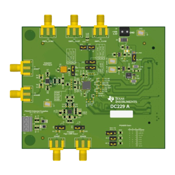
The ADS9227EVM presents two unique signal chain proposals for the user to evaluate: a high-bandwidth, fully-differential circuit that supports input frequencies up to 1MHz and a low-bandwidth, high-CMRR circuit with programmable gain that supports input frequencies up to 300kHz. - Page 4 Hardware www.ti.com Figure 2-1. THS4551 Fully-Differential Circuit for ADC A Figure 2-2. OPA320 Circuit to Buffer the ADS9227 VCMOUT Voltage ADS9227 Evaluation Module SBAU439 – JANUARY 2024 Submit Document Feedback Copyright © 2024 Texas Instruments Incorporated...
- Page 5 PGA855 and to protect the ADS9227 inputs from overdrive. Table 2-1. PGA855 Gain Settings A2 (JP8) A1 (JP9) A0 (JP10) Gain (V/V) 0.125 0.25 Figure 2-3. PGA855, High-CMRR Circuit for ADC B SBAU439 – JANUARY 2024 ADS9227 Evaluation Module Submit Document Feedback Copyright © 2024 Texas Instruments Incorporated...
-
Page 6: Voltage Reference
REFIO pin as an input and apply an external reference voltage to the pin. The ADS9227EVM include a provision for evaluating the REF7040 reference IC. The REF70xx family of high precision series voltage references offers the industry’s lowest noise (0.23ppm ), very low temperature drift coefficient (2ppm/°C), and high accuracy (±0.025%). -
Page 7: Power Supplies
The USB 3.0 port configuration for the PC is unknown. To switch to the external power configuration on the ADS9227EVM, move the jumper on J18 to the EXT_PWR position and use the J17 terminal block to provide the required 5.2-V to 5.5-V supply. To switch to the external power configuration on TSWDC155EVM, move the jumper on J2 to the 5 V (external) position and use the J10 terminal block or barrel jack connector to provide the required 5-V supply. -
Page 8: Digital Interface Connections
2.3 Digital Interface and Clock Inputs This section details the digital interface connections and clocking options for the ADS9227EVM. 2.3.1 Digital Interface Connections The ADS9227 uses both SPI and LVDS type interfaces. The SPI is a CMOS interface that is used to configure the internal device registers and consists of SCLK, SDI, SDO, CS, and SPI_EN. - Page 9 Hardware 2.3.2 Clock Select The ADS9227EVM offers the following options for providing the conversion clock to the ADS9227: a CMOS clock from the TSWDC155EVM, a CMOS clock from an external source, and an LVDS clock from external source. Table 2-2...
- Page 10 Section 2.2.1. 2. Physically connect J1 of the TSWDC155EVM to J27 of the ADS9227EVM. This component is the digital communications and power signal connection in default configuration. 3. Set jumper J18 to the FMC_PWR position so the TSWDC155EVM provides power. Otherwise, set J18 to EXT_PWR and connect an external 5.2-V to 5.5-V supply on screw terminal connection J17.
- Page 11 3.1 ADS9227EVM Software Reference 3.1.1 ADS9227EVM-GUI Software Installation This section details the installation and operation of the ADS9227EVM software graphical user interfaces (GUI). These software require the TSWDC155EVM (sold separately) controller to operate. The first step to installing the software (as shown in...
- Page 12 Software www.ti.com Figure 3-2. Software Installation - Part 2 ADS9227 Evaluation Module SBAU439 – JANUARY 2024 Submit Document Feedback Copyright © 2024 Texas Instruments Incorporated...
-
Page 13: Usb Driver Installation
6. Click on Have Disk in the pop-up window and navigate to: a. C:\Program Files\Texas Instruments\ADS92xx\bin\proj_lib\Sparrow\Bootloader Figure 3-3. Open Device Manager Figure 3-4. Update Driver With Device Manager SBAU439 – JANUARY 2024 ADS9227 Evaluation Module Submit Document Feedback Copyright © 2024 Texas Instruments Incorporated... - Page 14 Status message. For the Power Up and Program FPGA buttons, some status LEDs on the hardware illuminate. After all four buttons are pressed, the power on the ADS9227EVM is on and the ADS9227 device registers are configured. Press the bu o ns circled below.
- Page 15 FFT 4. Press “Start results. Capture” to collect data 3. Select Hanning type FFT window Figure 3-6. Initial Required Setup on the Capture Tab SBAU439 – JANUARY 2024 ADS9227 Evaluation Module Submit Document Feedback Copyright © 2024 Texas Instruments Incorporated...
- Page 16 3.1.5 Using the INL/DNL Tool The INL/DNL tool measures the linearity of the of the ADS9227EVM by applying a full-scale, low-distortion sinusoidal input signal. The accuracy improves if the number of hits per code is increased at the cost of extra test time.
- Page 17 To save the raw ADC output values, use the Capture tab. Figure 3-8. Using the Histogram Tab SBAU439 – JANUARY 2024 ADS9227 Evaluation Module Submit Document Feedback Copyright © 2024 Texas Instruments Incorporated...
- Page 18 SPI_EN SPI_EN DCLKP FCLKP RESETn RESET PWDNn PWDN Thermal_Pad ADS9227RHAT DCLKM FCLKM REFIO OUTF OUTS 0.1µF 10uF REF7040QFKHT Figure 4-1. ADS9227 Device Connections Schematic ADS9227 Evaluation Module SBAU439 – JANUARY 2024 Submit Document Feedback Copyright © 2024 Texas Instruments Incorporated...
- Page 19 PGA850RGT PBKG INN_B C20 39pF 51pF FDA_INN_B 100V AINM_B PGA855 Altium Symbol 60.4 0 R18 AINBM VMAMP INP_ext_B 10µF 100nF Figure 4-2. Input Connections SBAU439 – JANUARY 2024 ADS9227 Evaluation Module Submit Document Feedback Copyright © 2024 Texas Instruments Incorporated...
- Page 20 10uF 210k PGA855 External Supplies VS- ≥ -18V, VS+ ≤ +18V VMAMP VPAMP 5.11 5.11 MMSZ4705T1G MMSZ4705T1G Figure 4-3. Power Connections and Regulators Schematic ADS9227 Evaluation Module SBAU439 – JANUARY 2024 Submit Document Feedback Copyright © 2024 Texas Instruments Incorporated...
- Page 21 DOUTP_B DOUTM_B DCLKOUT FPGA_SMPL_CLKP FPGA_SMPL_CLKM SPI_EN 3P3VAUX SCLK 3P3V FPGA_SMPL_SYNC 3P3V 3P3V VADJ VADJ ASP-134488-01 ASP-134488-01 ASP-134488-01 ASP-134488-01 ASP-134488-01 Figure 4-4. Digital Connector Schematic SBAU439 – JANUARY 2024 ADS9227 Evaluation Module Submit Document Feedback Copyright © 2024 Texas Instruments Incorporated...
-
Page 22: Pcb Layout
Hardware Design Files www.ti.com 4.2 PCB Layout The figures below show the PCB layer plots for the ADS9227EVM. Figure 4-5. Top Overlay Figure 4-6. Top Layer Figure 4-7. GND Layer Figure 4-8. Power Layer ADS9227 Evaluation Module SBAU439 – JANUARY 2024 Submit Document Feedback Copyright ©... - Page 23 Hardware Design Files Figure 4-9. Bottom Layer Figure 4-10. Bottom Overlay SBAU439 – JANUARY 2024 ADS9227 Evaluation Module Submit Document Feedback Copyright © 2024 Texas Instruments Incorporated...
- Page 24 Hardware Design Files www.ti.com 4.3 Bill of Materials (BOM) Table 4-1 lists the ADS9227EVM bill of materials. Table 4-1. ADS9227EVM Bill of Materials Designator Quantity Value Description Package Reference Part Number Manufacturer C1, C2 CAP, CERM, 1uF, 25V, +/- 10%, X7R,...
- Page 25 Hardware Design Files Table 4-1. ADS9227EVM Bill of Materials (continued) Designator Quantity Value Description Package Reference Part Number Manufacturer C40, C41, C43, C44 CAP, CERM, 1 uF, 16 V, +/- 10%, X7R, C1608X7R1C105K080AC 0603 C45, C46 10uF CAP, CERM, 10 uF, 16 V, +/- 10%, X7R,...
- Page 26 Hardware Design Files www.ti.com Table 4-1. ADS9227EVM Bill of Materials (continued) Designator Quantity Value Description Package Reference Part Number Manufacturer R21, R22, R23, R24 49.9 RES, 49.9, 1%, 0.063 W, AEC-Q200 CRCW040249R9FKED Vishay-Dale Grade 0, 0402 RES, 33, 5%, 0.063 W, AEC-Q200 Grade...
- Page 27 Hardware Design Files Table 4-1. ADS9227EVM Bill of Materials (continued) Designator Quantity Value Description Package Reference Part Number Manufacturer Precision, 20 MHz, 0.9 pA Ib, RRIO, DBV0005A OPA320AIDBVT Texas Instruments CMOS Operational Amplifier, 1.8 to 5.5 V, -40 to 125 degC, 5-pin SOT23 (DBV5), Green (RoHS &...
-
Page 28: Related Documentation
® are registered trademarks of Microsoft Corporation. All trademarks are the property of their respective owners. 6 Related Documentation The following related documents are available for download through the Texas Instruments web site at www.ti.com. Table 6-1. Related Documentation Device... - Page 29 STANDARD TERMS FOR EVALUATION MODULES Delivery: TI delivers TI evaluation boards, kits, or modules, including any accompanying demonstration software, components, and/or documentation which may be provided together or separately (collectively, an “EVM” or “EVMs”) to the User (“User”) in accordance with the terms set forth herein.
- Page 30 www.ti.com Regulatory Notices: 3.1 United States 3.1.1 Notice applicable to EVMs not FCC-Approved: FCC NOTICE: This kit is designed to allow product developers to evaluate electronic components, circuitry, or software associated with the kit to determine whether to incorporate such items in a finished product and software developers to write software applications for use with the end product.
- Page 31 www.ti.com Concernant les EVMs avec antennes détachables Conformément à la réglementation d'Industrie Canada, le présent émetteur radio peut fonctionner avec une antenne d'un type et d'un gain maximal (ou inférieur) approuvé pour l'émetteur par Industrie Canada. Dans le but de réduire les risques de brouillage radioélectrique à...
- Page 32 www.ti.com EVM Use Restrictions and Warnings: 4.1 EVMS ARE NOT FOR USE IN FUNCTIONAL SAFETY AND/OR SAFETY CRITICAL EVALUATIONS, INCLUDING BUT NOT LIMITED TO EVALUATIONS OF LIFE SUPPORT APPLICATIONS. 4.2 User must read and apply the user guide and other available documentation provided by TI regarding the EVM prior to handling or using the EVM, including without limitation any warning or restriction notices.
- Page 33 Notwithstanding the foregoing, any judgment may be enforced in any United States or foreign court, and TI may seek injunctive relief in any United States or foreign court. Mailing Address: Texas Instruments, Post Office Box 655303, Dallas, Texas 75265 Copyright © 2023, Texas Instruments Incorporated...
-
Page 34: Important Notice
TI products. TI’s provision of these resources does not expand or otherwise alter TI’s applicable warranties or warranty disclaimers for TI products. TI objects to and rejects any additional or different terms you may have proposed. IMPORTANT NOTICE Mailing Address: Texas Instruments, Post Office Box 655303, Dallas, Texas 75265 Copyright © 2024, Texas Instruments Incorporated...
Need help?
Do you have a question about the ADS9227EVM and is the answer not in the manual?
Questions and answers