Table of Contents
Advertisement
Quick Links
This user's guide describes the characteristics, operation, and use of the ADS1x7xEVM-PDK. These
evaluation module kits (EVM-PDK) are an evaluation system for the ADS1278, a 24-bit, 8 channel, delta-
sigma analog-to-digital converter (ADC), the ADS1178, a 16-bit version of the ADS1278 and the
and ADS1174, which are 4 channel versions of the ADS1278 and ADS1178, respectively. The EVM-PDK
allows evaluation of all aspects of the ADS1x7x devices.
This document includes an EVM QuickStart, hardware and software details, bill of materials, and
schematic.
The following related documents are available through the Texas Instruments web site at
http://www.ti.com.
Device
ADS1278
ADS1274
ADS1178
ADS1174
REF5025
OPA2350
SBAU197A – February 2012 – Revised January 2016
Submit Documentation Feedback
ADS1x7xEVM-PDK
Table 1. EVM-Compatible Device Data Sheets
Literature Number
SBAS367
SBAS367
SBAS373
SBAS373
SBOS410
SBOS099
Copyright © 2012–2016, Texas Instruments Incorporated
SBAU197A – February 2012 – Revised January 2016
ADS1x7xEVM-PDK
Device
Literature Number
OPA1632
SBOS286
SN74LVC2G157
SCES207
TPS73018
SBVS054
TPS65131
SLVS493
PCA9535
SCPS129
User's Guide
ADS1274
1
ADS1x7xEVM-PDK
Advertisement
Table of Contents

Related Manuals for Texas Instruments ADS1x7xEVM-PDK


Summary of Contents for Texas Instruments ADS1x7xEVM-PDK
- Page 1 ADS1x7xEVM-PDK ADS1x7xEVM-PDK This user's guide describes the characteristics, operation, and use of the ADS1x7xEVM-PDK. These evaluation module kits (EVM-PDK) are an evaluation system for the ADS1278, a 24-bit, 8 channel, delta- sigma analog-to-digital converter (ADC), the ADS1178, a 16-bit version of the ADS1278 and the ADS1274 and ADS1174, which are 4 channel versions of the ADS1278 and ADS1178, respectively.
-
Page 2: Table Of Contents
................... J5 Configuration: Power-Supply Input ................... ADS1x7xEVM Bill of Materials Trademarks ADCPro is a trademark of Texas Instruments. C is a trademark of NXP Semiconductors, Inc. ADS1x7xEVM-PDK SBAU197A – February 2012 – Revised January 2016 Submit Documentation Feedback Copyright © 2012–2016, Texas Instruments Incorporated... -
Page 3: Evm Overview
EVM and the term evaluation module are synonymous with the ADS1178EVM/ADS1278EVM/ADS1174EVM/ADS1274EVM. For clarity of reading, this manual will refer only to the ADS1278EVM or ADS1x7xEVM-PDK, but operation of the EVM and kit for the ADS1178/ADS1274/ASD1174 is identical, unless otherwise noted. -
Page 4: Quick Start
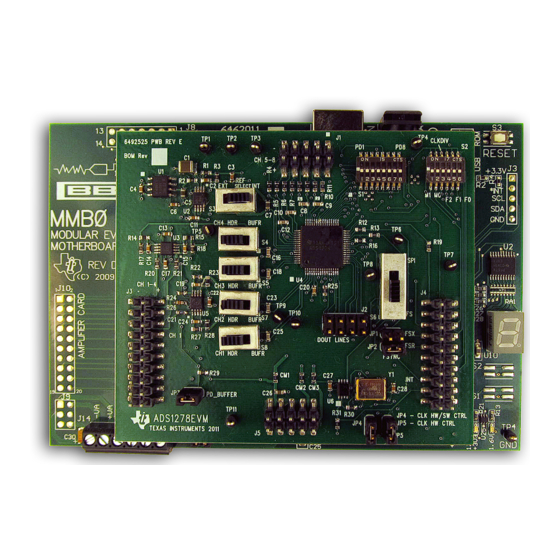
[1-2], [4-5], [7-8], [10-11] Jumpers installed to select FS serial interface format Channel 2 header connected to converter (not Header connected to converter (Left) buffered) ADS1x7xEVM-PDK SBAU197A – February 2012 – Revised January 2016 Submit Documentation Feedback Copyright © 2012–2016, Texas Instruments Incorporated... - Page 5 External clock source selected (invalid since using Short software control) ADS1x7xEVM-PDK Operation To prepare to evaluate the ADS1278 with the ADS1x7xEVM-PDK, complete the following steps: 1. Verify the jumpers on the ADS1x7xEVM are as shown in Figure 1 (note that these settings are the factory-configured settings for the EVM).
-
Page 6: Quick Reference
REF5025 or a external reference voltage that is connected to the reference pins of J3 (J3.18 = REFN and J3.20 = REFP). ADS1x7xEVM-PDK SBAU197A – February 2012 – Revised January 2016 Submit Documentation Feedback Copyright © 2012–2016, Texas Instruments Incorporated... -
Page 7: Using The Ads1178Evm-Pdk/Ads1278Evm-Pdk Plug-In Adcpro
The ADS1278 can acquire data from one to eight channels simultaneously. The Channel Enable tab (as shown in Figure 2) provides the control to power on or off each channel. SBAU197A – February 2012 – Revised January 2016 ADS1x7xEVM-PDK Submit Documentation Feedback Copyright © 2012–2016, Texas Instruments Incorporated... -
Page 8: Channel Enable
Disabled turn all the selector switches either ON or OFF. Settings Tab The Settings tab allows for the selection of the various clock frequencies, operating mode, data format, and other settings. ADS1x7xEVM-PDK SBAU197A – February 2012 – Revised January 2016 Submit Documentation Feedback Copyright © 2012–2016, Texas Instruments Incorporated... -
Page 9: Clock Settings And Mode
The maximum clock frequency is shown for the different converter options in Table SBAU197A – February 2012 – Revised January 2016 ADS1x7xEVM-PDK Submit Documentation Feedback Copyright © 2012–2016, Texas Instruments Incorporated... -
Page 10: Operating Modes: Clock Frequency
The About tab provides information on the EVM hardware and software versions. Plug-in Version is software version of ADCPro plug-in. Firmware Version is firmware version loaded and running on the processor. ADS1x7xEVM-PDK SBAU197A – February 2012 – Revised January 2016 Submit Documentation Feedback Copyright © 2012–2016, Texas Instruments Incorporated... - Page 11 Only one of FSYNC/DRDY signals should be connected at a time (JP1 or JP2). Channels 4-8 only available for ADS1278 and ADS1178. SBAU197A – February 2012 – Revised January 2016 ADS1x7xEVM-PDK Submit Documentation Feedback Copyright © 2012–2016, Texas Instruments Incorporated...
-
Page 12: Jumper And Switch Descriptions
For use in the ADS1x7xEVM-PDK, the state of these pins is controlled by software, using the I C port expanders (U7 and U8) on the EVM. When using the EVM with the EVM-PDK, the DIP switches S1 and S2 must all be switched down (toward the center of the board). -
Page 13: J3: Primary Analog Interface Pinout
DSP or micro controller interface board, such as the MMB0 if purchased as part of the ADS1278EVM- PDK, the 5-6K Interface HPA-MCUInterface boards which are available from Texas Instruments. For a list of compatible interface and/or accessory boards for the EVM or the ADS1278, see the relevant product folder on the TI web site. 5.5.1... -
Page 14: J4, Serial Interface Header
Pin 1 is top left-hand corner, located next to reference designator. DOUT1 buffered through a D flip-flop. See Section 5.5.3.1 below. ADS1x7xEVM-PDK SBAU197A – February 2012 – Revised January 2016 Submit Documentation Feedback Copyright © 2012–2016, Texas Instruments Incorporated... -
Page 15: J2, Doutx Header
In TDM mode, the data from all eight channels can be observed on the DOUT1 pin of the converter. The DOUT1 signal is used by the ADS1x7xEVM-PDK to read back and display all the channels. The digital data output pin on the digital interface header J4 is connected to DOUT1 signal via a D flip-flop. The D flip-flop provides a half cycle delay in order to align the data correctly to reach the higher speeds of the device. - Page 16 Resistor, Chip, 1/10W, 5% Rohm MCR03EZPJ473 Switch, SMD Low Profile 08 Position 218-8LPST These parts are not installed for ADS1274 and ADS1174 ADS1x7xEVM-PDK SBAU197A – February 2012 – Revised January 2016 Submit Documentation Feedback Copyright © 2012–2016, Texas Instruments Incorporated...
-
Page 17: Ads1X7Xevm Bill Of Materials
PCB, 3.31 In x 2.88 In x 0.062 In 6492525 Shunt, 100-mil, Black 929950-00 SHUNT JUMPER Samtec 2SN-BK-G Installed for ADS1278EVM-PDK. For other EVM-PDKs, the appropriate device will be installed. SBAU197A – February 2012 – Revised January 2016 ADS1x7xEVM-PDK Submit Documentation Feedback Copyright © 2012–2016, Texas Instruments Incorporated... - Page 18 NOTE: Page numbers for previous revisions may differ from page numbers in the current version. Changes from Original (February 2012) to A Revision ....................Page ......................• Changed step 4 of Section 2.2 Revision History SBAU197A – February 2012 – Revised January 2016 Submit Documentation Feedback Copyright © 2012–2016, Texas Instruments Incorporated...
- Page 19 0.1u 470k DGND AGND AGND CM2 0 DGND DVDD_26 DGND IOVDD CM3 0 TP11 IOVDD_22_23 Texas Instruments JP4 JP5 Setting CM1-3 are available for current monitoring AGND OFF ON Hardware External DGND Title ADS1278EVM OFF OFF Hardware Internal ON x...
- Page 20 [1,2] AVDD [1,2] REFP U2-A OUTA 0.1u 1 DNC 2 VIN 100u 3 TEMP VOUT 4 GND TRIM AGND [1,2,3] Texas Instruments Title ADS1278EVM Size Number <Number> 07APR11 G Hupp Date Drawn by G Hupp ads1278evm.sch Engineer Filename Sheet 2/9/2012...
- Page 21 ANP1 0.1u 1.5n 0.1u 0.1u ANN1 1.5n AGND AGND AGND ANP3 ANN3 ANN4 ANP4 ANN4 ANP4 REFN_HDR[1] REFP_HDR[1] AGND BRD_ANLG_IN Texas Instruments Title ADS1278EVM Size Number <Number> 07APR11 G Hupp Date Drawn by G Hupp ads1278evm.sch Engineer Filename Sheet 2/9/2012...
- Page 22 0.1u DGND IOVDD 0.1u DGND 1 A0 DGND 2 A1 DGND 3 A2 DGND 4 VSS DGND DGND DGND DGND Texas Instruments Title ADS1278EVM Size Number <Number> 07APR11 G Hupp Date Drawn by G Hupp ads1278evm.sch Engineer Filename Sheet 2/9/2012...
- Page 23 STANDARD TERMS FOR EVALUATION MODULES Delivery: TI delivers TI evaluation boards, kits, or modules, including any accompanying demonstration software, components, and/or documentation which may be provided together or separately (collectively, an “EVM” or “EVMs”) to the User (“User”) in accordance with the terms set forth herein.
- Page 24 FCC Interference Statement for Class B EVM devices NOTE: This equipment has been tested and found to comply with the limits for a Class B digital device, pursuant to part 15 of the FCC Rules. These limits are designed to provide reasonable protection against harmful interference in a residential installation.
- Page 25 【無線電波を送信する製品の開発キットをお使いになる際の注意事項】 開発キットの中には技術基準適合証明を受けて いないものがあります。 技術適合証明を受けていないもののご使用に際しては、電波法遵守のため、以下のいずれかの 措置を取っていただく必要がありますのでご注意ください。 1. 電波法施行規則第6条第1項第1号に基づく平成18年3月28日総務省告示第173号で定められた電波暗室等の試験設備でご使用 いただく。 2. 実験局の免許を取得後ご使用いただく。 3. 技術基準適合証明を取得後ご使用いただく。 なお、本製品は、上記の「ご使用にあたっての注意」を譲渡先、移転先に通知しない限り、譲渡、移転できないものとします。 上記を遵守頂けない場合は、電波法の罰則が適用される可能性があることをご留意ください。 日本テキサス・イ ンスツルメンツ株式会社 東京都新宿区西新宿6丁目24番1号 西新宿三井ビル 3.3.3 Notice for EVMs for Power Line Communication: Please see http://www.tij.co.jp/lsds/ti_ja/general/eStore/notice_02.page 電力線搬送波通信についての開発キットをお使いになる際の注意事項については、次のところをご覧ください。http:/ /www.tij.co.jp/lsds/ti_ja/general/eStore/notice_02.page 3.4 European Union 3.4.1 For EVMs subject to EU Directive 2014/30/EU (Electromagnetic Compatibility Directive): This is a class A product intended for use in environments other than domestic environments that are connected to a low-voltage power-supply network that supplies buildings used for domestic purposes.
- Page 26 Notwithstanding the foregoing, any judgment may be enforced in any United States or foreign court, and TI may seek injunctive relief in any United States or foreign court. Mailing Address: Texas Instruments, Post Office Box 655303, Dallas, Texas 75265 Copyright © 2018, Texas Instruments Incorporated...
- Page 27 IMPORTANT NOTICE FOR TI DESIGN INFORMATION AND RESOURCES Texas Instruments Incorporated (‘TI”) technical, application or other design advice, services or information, including, but not limited to, reference designs and materials relating to evaluation modules, (collectively, “TI Resources”) are intended to assist designers who are developing applications that incorporate TI products;...
Need help?
Do you have a question about the ADS1x7xEVM-PDK and is the answer not in the manual?
Questions and answers