Advertisement
Quick Links
Advertisement

Related Manuals for Max-Thrust Ruckus Balsa Pro-Build Series


Summary of Contents for Max-Thrust Ruckus Balsa Pro-Build Series
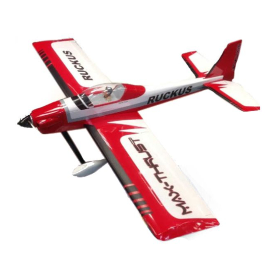
- Page 1 Instruction Manual...
- Page 2 It should not be operated by children without the supervision of a suitably experienced adult. Max-Thrust reserves the right to modify the specification of this model at any time. Safety Precautions 1. Do not attempt to repair or modify this aircraft with non-factory parts.
-
Page 3: Items Required
Items Required Some pictures throughout this manual may be of the prototype model and some details may now have changed. If you have any questions please contact us info@centuryuk.com. Tools: Philips Screwdriver Medium Philips Screwdriver Small Modelling Knife and Spare Blades 3mm Allen Key 2mm Allen Key 30 Minute Epoxy Glue... - Page 4 Building Your IC Ruckus IC Version. Using the 4mm x 25mm Phillips head screws (x4) and washers attached the engine mount to the bulkhead on the front of the model. Install the screws through the mount and make sure the mount is spaced correctly for your engine then test fit the cowl, 2 degrees of side thrust is built in to the model.
- Page 5 Building Your Electric Ruckus Electric Version. Screw the wooden motor mount on using the 4mm x 20mm cap head bolts and washers. Extend the lines on the mount so that you can make sure the motor is centred and drill 3mm holes to suit your motor.
- Page 6 Put the axles on to the alloy landing strut and tighten the 5mm nuts hard against each other. Put both washers on the inside of the leg to clear the wheel spats. When happy put a small drop of cyno on the threads near the nuts to stop them coming loose (or use thread lock).
- Page 7 Locate the push-rods and remove the metal quick-links, you will now be able to push them down the pre installed plastic guide tubes in the fuselage, be careful when the push-rods exit the fuselage use a sharp knife to cut the covering, re-affix the metal quick-links with the 2mm nuts once installed. IC Version.
- Page 8 IC Version. Make up the tank and install in to the fuselage using extra fuel tube to help route through to the engine. The clunk needs to be approx. 70mm long and the vent pipes need to be softly bent up to the top of the tank. Remember to tighten the screw to secure the bung in place in the tank. IC Version Only Remove the canopy by sliding it forward away from the magnets and then lift the back to remove.
- Page 9 IC Version. The On/Off switch is best installed on the non exhaust side of the model above the throttle servo. Photo shows prototype model. IC Version. Now you need to mount the cowl using 3mm x 10mm self tapping screws. Make 4 x 3mm holes in the cowl and 2mm holes around the firewall and self tap the screws in to the wood of the fuselage.
-
Page 10: Tail Feathers
Tail Feathers All of the hinges need to be glued in using slow CA. Start by gluing in the hinges to the tail and fin. The elevator and rudder can be fitted and glued in to place once you have checked the fit and made sure of full movement. - Page 11 Install the tail wheel assembly on to the rudder and glue in place using 30 minute epoxy. Install the control horns on to both the rudder and elevator using the 3x12mm self tapping screws on each. Now is a good time to apply the decals to the model as it is easier to handle. Glue the tail plane assembly into place using a thin coat of 30 minute epoxy making sure that it is in the correct position and square with the fuselage, when set you can glue the rudder assembly in to place and once dry screw the tail wheel bracket in to place using the M3 x 10mm self tapping screws once...
-
Page 12: Wing Assembly
Wing Assembly Remove the servo mounts from the wing halves and install your servos to the plates. If using standard size servos remove the laser perforated part so they fit. Pilot dill the holes you need to suit the servos you are installing. Fit the aileron push rods to the servo horn once the servo is centred and the horn is fitted. - Page 13 The holes for the 4 2x10mm self tapping screws are pre drilled in the servo cover, locate them and use them as a guide to drill 1.5mm holes for the screws to hold the servo hatch/mount in place on the wing.
- Page 14 Designed and Distributed by Century UK LTD. 7 Anchor Business Park Castle Road Sittingbourne KENT MADE IN VIETNAM ME10 3AE United Kingdom 01795 437056...
Need help?
Do you have a question about the Ruckus Balsa Pro-Build Series and is the answer not in the manual?
Questions and answers