Advertisement
Quick Links
Advertisement

Related Manuals for Max-Thrust Double Trouble Balsa Pro-Built Series


Summary of Contents for Max-Thrust Double Trouble Balsa Pro-Built Series
- Page 1 Instruction Manual...
- Page 2 It should not be operated by children without the supervision of a suitably experienced adult. Max-Thrust reserves the right to modify the specification of this model at any time. Safety Precautions 1. Do not attempt to repair or modify this aircraft with non-factory parts.
-
Page 3: Items Required
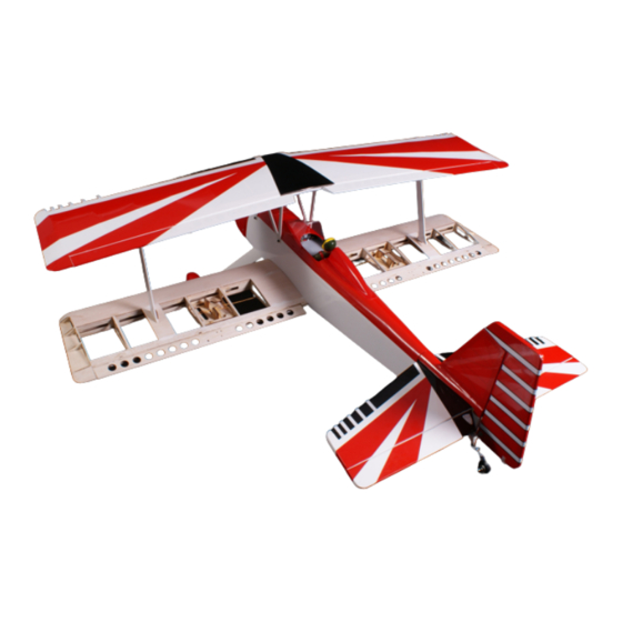
Items Required Some pictures throughout this manual may be of the prototype model and some details may now have changed. If you have any questions please contact us info@centuryuk.com. Tools: Philips Screwdriver Medium Philips Screwdriver Small Modelling Knife and Spare Blades 3mm Allen Key 2mm Allen Key 30 Minute Epoxy Glue... - Page 4 Building Your Double Trouble Start by glueing all of the hinges in place using CA Glue. Medium or Thick Slow set is best. Check for any wrinkles in the covering and using a film iron shrink these back so the film is tight. Install the control horns on to the Ailerons and also the upper and lower aileron connector plates.
- Page 5 Building Your Double Trouble Next is the rudder horn which is made up by using a M3 x 45mm screw, 2 x nylon adaptors, 2 x M3 Nuts and 2 washers. Thread the plastic adaptor to the end of the screw and then run a 3mm nut followed by a washer to just past the middle of the screw.
- Page 6 Building Your Double Trouble Installing the aileron servos. Remove the cover and cut the servo area to fit your choice of servo. Screw the servos in to the covers using the screws supplied with your servos. Make sure you centre the servo and fit the servo control arm.
- Page 7 Building Your Double Trouble Landing gear. Put a wheel on the axle by removing the collet, the collet should be flush with the end of the axle and the wheel should spin freely. Run a nut and then a washer on to the threaded section and place the wheel inside the spat.
- Page 8 Building Your Double Trouble Tail Feathers. First step is to place the tailplane in position and then mark and remove a triangular section of the film from both sides of the tail plane so that the glue can stick to the balsa correctly. Make this slightly smaller on the top to the bottom as the fin fairings are slightly smaller than the tail plane seat on the fuselage.
- Page 9 Building Your Double Trouble Once the tailplane is glued in place you can fit the fin and rudder again using either 5 or 30 minute epoxy. Make sure the lower rudder hinge is located in place before gluing the assembly in place. Offer the tail wheel assembly to the fuselage and mark the screw locations and pilot drill 2mm holes and then fit using the screws provided.
- Page 10 Building Your Double Trouble Make up the rudder pull pull system by fitting a metal quick link on to the brass adaptor with a nut. Put a metal ferrule on to the wire and then take the wire through the eyelet and then back through the ferrule and loop it back through and tuck the end in to the ferrule and crimp the ferrule tight.
- Page 11 Building Your Double Trouble Building Your IC Double Trouble IC Version. Install the T-mounts for the engine to the firewall, We used a OS 46AX with a 12x6 Gemfan prop in the prototype model. There is 3.5 degrees of side thrust built into the mount so the mount make look like it is off centre.
- Page 12 Building Your Electric Double Trouble Building Your Double Trouble Electric Version. Screw the wooden motor mount on using the 4mm x 14mm cap head screws and washers. Centre your motor on the mount and mark the bolt hole locations on the motor mounting plate and then drill these to suit.
- Page 13 Building Your Double Trouble Fit the upper wing supports using the M3 x 12mm Cap Head Screws. Turn the model over and sit it on the wing supports and fin, from here you can now fit the rudder and elevator servos. If you are building the IC version you can now install the throttle servo and switch to the non exhaust side of the model in the pre cut hole.
- Page 14 Building Your Double Trouble Bolt the top wing in to position on the centre struts using the M3 x 12mm cap head bolts and washers, these can be fully tightened at this stage (if you wish you could fit m3 nylock nuts for added security but this will add to the assembly time at the field but a good idea if you are leaving it assembled) Screw the outer wing struts in to place also using M3 x 12mm cap head bolts and washers but do not fully tighten until the bottom wing is in place.
- Page 15 Building Your Double Trouble Next install the lower wing and secure using the M8 Thumb screws, line up the outer wing struts and secure in place with the M3 x 12mm Cap head screws and washers. You can now fully tighten all the bolts for the wing struts.
- Page 16 Building Your Double Trouble The pilot, screen and fairing are optional parts to fit. The screen needs to be cut to suit and we added some red trim to the back of the screen to finish it off. Secure the screen and fairing in place using Zap-A-Dap-A-Goo directly to the film covering.
- Page 17 Building Your Double Trouble Designed and Distributed by Century UK LTD. 7 Anchor Business Park Castle Road Sittingbourne KENT MADE IN VIETNAM ME10 3AE United Kingdom 01795 437056...
Need help?
Do you have a question about the Double Trouble Balsa Pro-Built Series and is the answer not in the manual?
Questions and answers