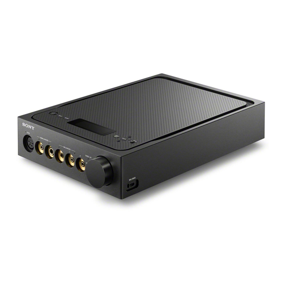
Sony TA-ZH1ES Service Manual
Headphone amplifier
Hide thumbs
Also See for TA-ZH1ES:
- Operating instructions manual (100 pages) ,
- Operating instructions manual (45 pages)
Table of Contents
Advertisement
SERVICE MANUAL
Ver. 1.0 2016.10
Note:
Be sure to keep your PC used for service and
checking of this unit always updated with the
latest version of your anti-virus software.
In case a virus affected unit was found during
service, contact your Service Headquarters.
Section for headphone amplifier
PHONES (headphones) section
Rated power output
BALANCED: 1,200 mW + 1,200 mW (32 Ω,
THD 1%)
Frequency characteristics
BALANCED: 4 Hz - 80 kHz (-3 dB, D.C.PHASE
LINEARIZER OFF)
Playing frequency range
BALANCED: 4 Hz - 200 kHz (D.C.PHASE
LINEARIZER OFF)
Supported impedance
Area
Supported impedance
U.S.A. and
12 Ω - 600 Ω
Canada
Other countries
8 Ω - 600 Ω
Input section
USB-B section
Supported format
PCM 2ch: 44.1/48/88.2/96/176.4/192/352.8/
384/705.6/768 kHz (16/24/32 bit)
DSD 2ch: 2.8/5.6/11.2/22.4 MHz (1 bit)
9-896-334-01
2016J33-1
Sony Video & Sound Products Inc.
©
2016.10
SPECIFICATIONS
WALKMAN port (for WALKMAN®/Xperia™
connection) section
Supported format
PCM 2ch: 44.1/48/88.2/96/176.4/192/352.8/
384 kHz (16/24/32 bit)
DSD 2ch: 2.8/5.6/11.2 MHz (1 bit)
COAX (coaxial) IN section
Input impedance
75 Ω
Supported format
PCM 2ch: 32/44.1/48/88.2/96/176.4/192 kHz
(16/24 bit)
OPT (optical) IN section
Supported format
PCM 2ch: 32/44.1/48/88.2/96 kHz (16/24 bit)
LINE IN L/R section
Maximum input voltage
2 Vrms
Input impedance
50 kΩ
Pre-out section
PRE OUT L/R section
Output voltage
2 Vrms (Fixed)
Output impedance
100 Ω
TA-ZH1ES
Australian Model
General
Power requirements
Area
Power requirements
U.S.A., Canada
120 V, 50/60 Hz
and Taiwan
Other countries
220 V - 240 V, 50/60 Hz
Power consumption
35 W
Power consumption (during standby mode)
0.3 W
Dimensions (w/h/d) (including projecting parts)
Approx. 210 mm × 65 mm × 314 mm
(8.27 in × 2.56 in × 12.37 in)
Mass
Approx. 4.4 kg (9.7 lb)
Supplied Accessories
Headphone amplifier
AC power cord (mains lead)
USB cable (USB-A/USB-B)
Digital cable for WALKMAN®
Remote control
R03 (size AAA) batteries
Operating instructions
Precautions/Specifications
Design and specifications are subject to
change without notice.
HEADPHONE AMPLIFIER
US Model
Canadian Model
AEP Model
UK Model
E Model
Chinese Model
On Copyrights
WALKMAN® and WALKMAN® logo are
registered trademarks of Sony
Corporation.
"Xperia" and "Xperia Tablet" are
trademarks of Sony Mobile
Communications AB.
Macintosh and Mac OS are trademarks of
Apple Inc., registered in the U.S. and other
countries.
Windows, the Windows logo, and
Windows Media are either registered
trademarks or trademarks of Microsoft
Corporation in the United States and/or
other countries.
This product is protected by certain
intellectual property rights of Microsoft
Corporation. Use or distribution of such
technology outside of this product is
prohibited without a license from
Microsoft or an authorized Microsoft
subsidiary.
The system names and product names
indicated in this manual are generally the
trademarks or registered trademarks of
the manufacturer.
™ and ® marks are omitted in this manual.
Advertisement
Table of Contents

Related Manuals for Sony TA-ZH1ES


Summary of Contents for Sony TA-ZH1ES
- Page 1 DSD 2ch: 2.8/5.6/11.2/22.4 MHz (1 bit) PRE OUT L/R section Operating instructions Output voltage Precautions/Specifications 2 Vrms (Fixed) Design and specifications are subject to Output impedance change without notice. 100 Ω HEADPHONE AMPLIFIER 9-896-334-01 2016J33-1 Sony Video & Sound Products Inc. © 2016.10...
- Page 2 LES DIAGRAMMES SCHÉMATIQUES ET LA LISTE DES PIÈCES SONT CRITIQUES POUR LA SÉCURITÉ DE FONC- TIONNEMENT. NE REMPLACER CES COMPOSANTS QUE PAR DES PIÈCES SONY DONT LES NUMÉROS SONT DON- NÉS DANS CE MANUEL OU DANS LES SUPPLÉMENTS PUBLIÉS PAR SONY.
-
Page 3: Table Of Contents
TA-ZH1ES TABLE OF CONTENTS SERVICING NOTES 5-7. Printed Wiring Board - DIGITAL Board (Side B) - ..41 ..........5-8. Schematic Diagram - DIGITAL Board (1/10) - ....42 5-9. Schematic Diagram - DIGITAL Board (2/10) - ....43 DISASSEMBLY 5-10. -
Page 4: Servicing Notes
TA-ZH1ES SECTION 1 SERVICING NOTES The SERVICING NOTES contains important information for servicing. Be sure to read this section before repairing the unit. UNLEADED SOLDER DESTINATION IDENTIFICATION Boards requiring use of unleaded solder are printed with the lead- Distinguish by Part No. and Destination code of the model number free mark (LF) indicating the solder contains no lead. - Page 5 MUC-S20BL1 Operation checking software: For each operation checks, download the following software from the support website etc. of Sony as necessary, and use them. For details of the method etc. of download and install, refer to the instruction manual. •...
-
Page 6: Disassembly
TA-ZH1ES SECTION 2 DISASSEMBLY • This set can be disassembled in the order shown below. 2-1. DISASSEMBLY FLOW 2-26. SERVICE POSITION (Page 21) 2-2. PLATE (BTM) BLOCK (Page 7) 2-22. POWER SUPPLY BOARD 2-3. CHASSIS BLOCK-1 (Page 18) (Page 7) 2-4. -
Page 7: Plate (Btm) Block
TA-ZH1ES Note: Follow the disassembly procedure in the numerical order given. 2-2. PLATE (BTM) BLOCK 1 eight screws (BVTP3 2 Insert a hex wrench, etc. into a ventilation hole on the plate (BTM) block and lift the plate (BTM) block. -
Page 8: Chassis Block-2
TA-ZH1ES 2-4. CHASSIS BLOCK-2 Note 1: When installing the chassis block, push the cables into chassis block the inside and be careful so that they do not get pinched. bottom side Press. front side Press. frame (wall) block Press. 1 Lift the chassis block in the direction of the arrow... -
Page 9: Top Panel Block, Frame (Wall) Block
TA-ZH1ES 2-5. TOP PANEL BLOCK, FRAME (WALL) BLOCK Push the XLR CONNECTOR board 1 Remove the DISPLAY board cable wire with lug terminal to the inside. from the two wiring stoppers. 2 screw (BVTP3 Push the wire with lug terminal... -
Page 10: Display Board Block
TA-ZH1ES 2-6. DISPLAY BOARD BLOCK Note: Be careful that it does not obstruct the screw hole. screw hole 2 screw guide line 1 cushion (LED) cushion (BVTP3 (LED) 3 wiring stopper 2 six screws (BVTP3 DISPLAY board front side 2 screw... -
Page 11: Usb Micro Board
TA-ZH1ES 2-8. USB MICRO BOARD tallati 8 USB MICRO board micro USB connector Note: When installing the USB MICRO board, hole align the hole and rib. front side hole 7 connector 5 Remove the USB MICRO (CN4203) board block in the direction top side of the arrow. -
Page 12: Vol Board
TA-ZH1ES 2-10. VOL BOARD 3 screw 6 collar (damper) (BVTP3 3 screw collar (damper) (BVTP3 5 bushing (damper) 5 bushing 6 collar (damper) (damper) – – groove 7 VOL board VOL board 4 housing (VOL) 3 screw boss (BVTP3 5 bushing Not deformed. -
Page 13: Jack Board
TA-ZH1ES 2-12. 6.3 JACK BOARD 1 two screws (BVTP2.6 3 6.3 JACK board 2 Draw the jack out of the hole. front side hole bottom side rear side top side 2-13. 3.5 JACK BOARD BLOCK 3 3.5 JACK board block... -
Page 14: Jack Board, Holder (Jack)
TA-ZH1ES 2-14. 3.5 JACK BOARD, HOLDER (JACK) 8 ground (HP-S) 9 holder (jack) holder (jack) Align with 4 Remove the 3.5 JACK board block the corner. in the direction of the arrow. boss front side 7 ground (HP-L) block 2 screw (BVTP2.6... -
Page 15: Ac Inlet (Ac1)-1
TA-ZH1ES 2-16. AC INLET (AC1)-1 • Continued on 2-17 (page 16). Note 1: The color of the AC inlet cable has been changed in the middle 4 Push in between of production. The cable color of the former type is used here. -
Page 16: Ac Inlet (Ac1)-2
TA-ZH1ES 2-17. AC INLET (AC1)-2 front side hole top side – – 2 Draw the AC inlet cable out of the hole. bottom side rear side 1 two screws (BV/ring) (L = 8.0 mm) 3 AC inlet (AC1) 2-18. POWER TRANSFORMER (T001)-1 •... -
Page 17: Power Transformer (T001)-2, Plate (Tr)
TA-ZH1ES 2-19. POWER TRANSFORMER (T001)-2, PLATE (TR) 1 screw 2 wiring stopper (BV3 1 screw (BV3 tio di e tio o t e p te 2 wiring Note: When installing the plate (TR), check that the round 3 power transformer stopper shapes are in the correct orientation. -
Page 18: Usb A Board
TA-ZH1ES 2-21. USB A BOARD 4 Remove the USB A board block in the direction of the arrow. 6 sheet (blind) 5 USB A board cable connector (CN5602) 7 USB A board front side Note: Be careful of the orientation of the text and affix so that the screws are not overlapped. -
Page 19: Digital Board
TA-ZH1ES 2-23. DIGITAL BOARD 4 AC inlet cable connector (CN102) 1 LINE OUT board cable Twist the LPF board connector (CN002) cable three times. DIGITAL board front side bottom side rear side 3 USB A board cable rear side connector (CN600) -
Page 20: Line In Board, Line Out Board, Lpf Board
TA-ZH1ES 2-24. LINE IN BOARD, LINE OUT BOARD, LPF BOARD 8 Draw the LINE OUT board 4 AC inlet cable cable out of the slit. 1 LINE OUT board cable connector (CN102) Note 1: Take care not to damage connector (CN002) the connector and cable. -
Page 21: Dsp Board
TA-ZH1ES 2-25. DSP BOARD 1 three screws 1 screw (BV3 (BV3 2 wiring stopper 5 DSP board CN3002 4 sheet (DSP) front side DIGITAL board bottom side rear side 3 connector (CN605) 2-26. SERVICE POSITION Note: Insert an insulation board, etc. here so that the metal part of the chassis block and the frame (wall) block do not touch. -
Page 22: Test Mode
TA-ZH1ES SECTION 3 TEST MODE • Each operation buttons (top view) SOFTWARE VERSION CHECK It can be check the each software version. button [ENTER] button button Procedure: [INPUT] button Display window 1. Press the [ ] button to turn the power on. - Page 23 TA-ZH1ES USB MEMORY ACCESS CHECK SHIPMENT SETTING MODE It can be check, whether USB memory is a normally accessed. It can return the main unit to the factory shipment state. Note 1: Prepare the USB memory with access lamp. Procedure: Procedure: 1.
-
Page 24: Troubleshooting
TA-ZH1ES SECTION 4 TROUBLESHOOTING 1. Power does not turn on Power does not turn on. The condition does not change even after reconnecting the Complete when turned on. POWER SUPPLY board to the DIGITAL board. The condition does not change even after connecting the Complete to after replacing the POWER SUPPLY board to new POWER SUPPLY board to the DIGITAL board. - Page 25 TA-ZH1ES 2. Sound is not outputted from the headphone Sound is not outputted from the headphone. The headphone plug is inserted all the way (with detection switch of the Insert the headphone plug all the way. headphone plug). The condition does not change even...
- Page 26 TA-ZH1ES – From page 25 – No sound from UNBALANCED-2 (J5050 on the 6.3 JACK board). The connection cable of the connector (CN004) that is Re-insert or repair the connection cable. connected from the 6.3 JACK board to the DIGITAL board is not removed nor broken.
- Page 27 TA-ZH1ES – From page 26 – No sound from BALANCED-2 (J5002, J5003 on the 3.5 JACK board). The connection cable that connects the connector (CN5002) Re-insert or repair the connection cable. on the 3.5 JACK board and the connector (CN010) on the DIGITAL board is not removed nor broken.
- Page 28 TA-ZH1ES 3. Handling fl ow for each input signal 3-1. No sound from WALKMAN (micro USB) input In advance to check the following two points. • The WALKMAN connected are target device. • The digital cable for WALKMAN is correctly inserted all the way.
- Page 29 TA-ZH1ES 3-2. No sound from USB-B input In advance to check the following two points. • If connecting the PC (personal computer) of the Windows OS, the correct USB terminal driver is installed to the PC (personal computer). • This unit is connected to the PC (personal computer) with a USB cable.
- Page 30 TA-ZH1ES 3-3. No sound from COAX IN and OPT IN input In advance to check the following two points. • Using sound source of the support sampling frequencies of up to 192 kHz for COAX IN, and up to 96 kHz for OPT IN.
- Page 31 TA-ZH1ES 3-4. No sound (or low sound) from LINE IN input In advance to check the following a point. • Connected to PS-HX500 (record player) through the EQ amplifi er. (An RIAA curve correction amplifi er that phono amplifi er or EQ amplifi er etc. is required even for playback of regular records) No sound (or low sound) from LINE IN input.
- Page 32 TA-ZH1ES 4. The WALKMAN does not charge The WALKMAN does not charge. The condition does not change even after connecting the new Replace the POWER SUPPLY board POWER SUPPLY board to the to new board. DIGITAL board. The toggle portion of the detection...
- Page 33 TA-ZH1ES 5. The protection feature is activated (“PROTECTOR” appears) 7. Other The protection feature is activated The GAIN switch does not work: (“PROTECTOR” appears). • Check if the switch (S4001) on the DISPLAY board is broken. • Check if there is a problem with the connection cable that con- nects the connector (CN4002) on the DISPLAY board and the connector (CN604) on the DIGITAL board.
-
Page 34: Diagrams
TA-ZH1ES SECTION 5 DIAGRAMS 5-1. BLOCK DIAGRAM - INPUT Section - DIGITAL AUDIO INTERFACE RECEIVER, SAMPLE RATE A/D CONVERTER CONVERTER FPGA IC402 IC405 IC700 (1/3) WAVE J400 SHAPER RXIN6 DATAOUT 16 9 SDTI SDTO H1 IO/DIFFIO_L13N COAX IN IC401 BCKOUT 14... -
Page 35: Block Diagram - Dsp Section
TA-ZH1ES 5-2. BLOCK DIAGRAM - DSP Section - SYSTEM CONTROLLER FPGA DSP1 DSP2 IC601 (2/5) IC700 (2/3) IC3001 IC3000 SIGNAL PATH FPGA EPCQ MOSI 130 D1 IO/DIFFIO_L5N/DATA1_ASDO IO/DIFFIO_R35N Y22 42 DAI_P19 DAI_P15 62 42 DAI_P19 : AUDIO (DIGITAL) D2 IO/DIFFIO_L5P... -
Page 36: Block Diagram - Amp Section
TA-ZH1ES 5-3. BLOCK DIAGRAM - AMP Section - FPGA RECLOCK GATE DRIVE HPOUT_LP, HPOUT_RP, IC700 (3/3) IC800 IC808 HPOUT_LP_HYB_OUT, HPOUT_RP_HYB_OUT BOOSTER HPOUT_LP >002B IO/DIFFIO_B10N AB7 MUTING Q801 IC804 IO/DIFFIO_B6P AB6 (Page 37) BOOSTER Q800 RECLOCK GATE DRIVE IC801 IC809 HPOUT_RP... -
Page 37: Block Diagram - Output Section
TA-ZH1ES 5-4. BLOCK DIAGRAM - OUTPUT Section - HPOUT_LP, HPOUT_RP, HP_L35_DET HPOUT_LP_HYB_OUT, HPOUT_RP_HYB_OUT J5002 HPOUT_LP SWITCHING >002B PH003 (Page 36) BALANCED HP_R35_DET ( 3.5) HPOUT_RP SWITCHING PH007 J5003 RY006 HP_44_DET J5200 BALANCED ( 4.4) RY007 HPOUT_LP_HYB_OUT SWITCHING PH006 SWITCHING SWITCHING... -
Page 38: Block Diagram - Panel/Power Supply Section
TA-ZH1ES 5-5. BLOCK DIAGRAM - PANEL/POWER SUPPLY Section - OLED1 SYSTEM CONTROLLER OLED DISPLAY IC601 (5/5) SDIN 39 ELW2101AC SDIN SCLK 40 ELW2101AC SCLK 41 ELW2101AC CSB 42 ELW2101AC DC RSTB 38 ELW2101AC RSTB REMOTE CONTROL DIGITAL RECEIVER 93 SIRCS... - Page 39 TA-ZH1ES THIS NOTE IS COMMON FOR PRINTED WIRING BOARDS AND SCHEMATIC DIAGRAMS. • Circuit Boards Location (In addition to this, the necessary note is printed in each block.) DIGITAL board LINE IN board For Printed Wiring Boards. For Schematic Diagrams.
-
Page 40: Printed Wiring Board - Digital Board (Side A)
TA-ZH1ES 5-6. PRINTED WIRING BOARD - DIGITAL Board (Side A) - • See page 39 for Circuit Boards Location. • : Uses unleaded solder. DSP BOARD (Page 54) >04P CN3002 DIGITAL BOARD (SIDE A) RY001, 002, 004, 006, 007, 901... -
Page 41: Printed Wiring Board - Digital Board (Side B)
TA-ZH1ES 5-7. PRINTED WIRING BOARD - DIGITAL Board (Side B) - • See page 39 for Circuit Boards Location. • : Uses unleaded solder. DIGITAL BOARD (SIDE B) C338 317 REG BOARD (Page 64) R309 >17P CN351 C855 JL425 JL602... -
Page 42: Schematic Diagram - Digital Board (1/10)
TA-ZH1ES 5-8. SCHEMATIC DIAGRAM - DIGITAL Board (1/10) - • See page 65 for Waveforms. • See page 68 for IC Block Diagrams. DIGITAL BOARD (1/10) >101S DIGITAL TMS320_I2C_SCL BOARD CN402 (4/10) TMS320_I2C_SDA (Page 45) JL419 R457 Lch_N ADC-DATA JL420... -
Page 43: Schematic Diagram - Digital Board (2/10)
TA-ZH1ES 5-9. SCHEMATIC DIAGRAM - DIGITAL Board (2/10) - • See page 68 for IC Block Diagrams. • See page 73 for IC Pin Function Description. DIGITAL BOARD (2/10) IC505 SERIAL FLASH IC505 MX25L4006EM1I-12G JL501 JL506 JL502 SO/SIO1 HOLD USB1.8V JL505 >105S... -
Page 44: 5-10. Schematic Diagram - Digital Board (3/10)
TA-ZH1ES 5-10. SCHEMATIC DIAGRAM - DIGITAL Board (3/10) - • See page 73 for IC Pin Function Description. DIGITAL BOARD (3/10) >109S DIGITAL BOARD (4/10) (Page 45) FB704 JL703 FPGA2.5V >111S FB703 JL700 DIGITAL DSP-FPGA_3.3V JL701 BOARD FPGA1.2V (9/10) JL702... -
Page 45: Schematic Diagram - Digital Board (4/10)
TA-ZH1ES 5-11. SCHEMATIC DIAGRAM - DIGITAL Board (4/10) - • See page 65 for Waveforms. • See page 68 for IC Block Diagrams. • See page 73 for IC Pin Function Description. (Page 52) (Page 48) >04S BOARD DIGITAL BOARD (4/10) (1/2) >117S... -
Page 46: Schematic Diagram - Digital Board (5/10)
TA-ZH1ES 5-12. SCHEMATIC DIAGRAM - DIGITAL Board (5/10) - • See page 65 for Waveforms. • See page 68 for IC Block Diagrams. DIGITAL BOARD (5/10) R876 R879 >120S C845 REG_1.3_14V_L 0.001 REG_12V_L DIGITAL BOARD REG_5V_L 5 6 7 8... -
Page 47: Schematic Diagram - Digital Board (6/10)
TA-ZH1ES 5-13. SCHEMATIC DIAGRAM - DIGITAL Board (6/10) - • See page 68 for IC Block Diagrams. DIGITAL BOARD (6/10) E-VOL-R-OUT >126S E-VOL-L-OUT DIGITAL CL902 BOARD HPOUT_RP_HYB_OUT (7/10) (Page 48) HPOUT_LP_HYB_OUT IC900 BUFFER AMP IC906 IC900 NJM8068G(TE2) R900 R904 R914 1.5k... -
Page 48: Schematic Diagram - Digital Board (7/10)
TA-ZH1ES 5-14. SCHEMATIC DIAGRAM - DIGITAL Board (7/10) - • See page 68 for IC Block Diagrams. DIGITAL BOARD (7/10) E-VOL-L-OUT R023 C017 >126S 220k E-VOL-R-OUT DIGITAL CN002 R021 RY002 HPOUT_RP_HYB_OUT BOARD R024 C018 (6/10) 220k HPOUT_LP_HYB_OUT >07S (Page 47) -
Page 49: Schematic Diagram - Digital Board (8/10)
TA-ZH1ES 5-15. SCHEMATIC DIAGRAM - DIGITAL Board (8/10) - • See page 68 for IC Block Diagrams. DIGITAL BOARD (8/10) IC307 +15V REGULATOR IC307 NJM78M15DL1A-TE1 17.9 14.7 CN301 CL304 C317 C320 C342 C325 C327 C329 UN-REG-IN >14S 2200 0.01 UN-REG-IN... -
Page 50: Schematic Diagram - Digital Board (9/10)
TA-ZH1ES 5-16. SCHEMATIC DIAGRAM - DIGITAL Board (9/10) - • See page 65 for Waveforms. • See page 68 for IC Block Diagrams. (Page 66) POWER >18S SUPPLY DIGITAL BOARD (9/10) BOARD CN2011 CN210 Q200 HN1B01FU POWER CONTROL USB5.2V USB5.2V R202 USB5.2V... -
Page 51: Schematic Diagram - Digital Board (10/10)
TA-ZH1ES 5-17. SCHEMATIC DIAGRAM - DIGITAL Board (10/10) - • See page 68 for IC Block Diagrams. T001 MAIN POWER TRANSFORMER >16S DIGITAL BOARD (8/10) CN300 (Page 49) NOT REPLACEABLE: BUILT IN TRANSFORMER (CHASSIS) DIGITAL BOARD (10/10) CN101 C115 Q100... -
Page 52: Schematic Diagram - Dsp Board (1/2)
TA-ZH1ES 5-18. SCHEMATIC DIAGRAM - DSP Board (1/2) - • See page 65 for Waveforms. • See page 73 for IC Pin Function Description. DSP BOARD (1/2) R3079 C3052 R3092 ET3004 C3053 C3067 C3032 C3033 C3035 C3042 C3039 (CHASSIS) 0.001... -
Page 53: Schematic Diagram - Dsp Board (2/2)
TA-ZH1ES 5-19. SCHEMATIC DIAGRAM - DSP Board (2/2) - • See page 65 for Waveforms. • See page 73 for IC Pin Function Description. DSP BOARD (2/2) >201S BOARD (1/2) C3006 (Page 52) C3007 C3009 C3013 C3002 C3016 C3000 R3015... -
Page 54: Printed Wiring Board - Dsp Board
TA-ZH1ES 5-20. PRINTED WIRING BOARD - DSP Board - 5-21. PRINTED WIRING BOARD - LPF Board - • See page 39 for Circuit Boards Location. • : Uses unleaded solder. • See page 39 for Circuit Boards Location. • : Uses unleaded solder. -
Page 55: Schematic Diagram - Lpf Board
TA-ZH1ES 5-22. SCHEMATIC DIAGRAM - LPF Board - • See page 68 for IC Block Diagrams. LPF BOARD R5413 5.6k IC5403 LOW-PASS FILTER IC5403 IC5401 NJM2746E(TE2) R5412 LINE AMP, CENTER VOLTAGE GENERATOR C5410 0 IC5401 NJM2746E(TE2) [4.1] [4.9] [4.9] [4.1]... -
Page 56: Printed Wiring Boards - Line/Usb Section
TA-ZH1ES 5-23. PRINTED WIRING BOARDS - LINE/USB Section - • See page 39 for Circuit Boards Location. • : Uses unleaded solder. LINE IN BOARD LINE IN BOARD USB MICRO BOARD (COMPONENT SIDE) (CONDUCTOR SIDE) (SIDE A) CN4203 C4201 ET4201... -
Page 57: Schematic Diagram - Line/Usb Section
TA-ZH1ES 5-24. SCHEMATIC DIAGRAM - LINE/USB Section - LINE IN BOARD USB MICRO BOARD S4201 WALKMAN CL5104 DETECT J5101 CL5106 C4201 ET4201 0.01 LINE IN CL5101 C5100 R5100 CN5101 C4206 C4202 100p 4.7p CL5100 (CHASSIS) CN4203 >21S C4204 SHELD_GND BOARD... -
Page 58: Printed Wiring Board - 3.5 Jack Board
TA-ZH1ES 5-25. PRINTED WIRING BOARD - 3.5 JACK Board - • See page 39 for Circuit Boards Location. • : Uses unleaded solder. 3.5 JACK BOARD (COMPONENT SIDE) C5020 C5005 ET5002 D5004 D5003 D5011 (CHASSIS) DSD RE. D5005 - 5011... -
Page 59: Schematic Diagram - 3.5 Jack Board
TA-ZH1ES 5-26. SCHEMATIC DIAGRAM - 3.5 JACK Board - 3.5 JACK BOARD R5009 D5009 4.7k SCMP13WBC8W1FU XLR4 CN5001 3.5L– C5017 2200p >11S 3.5L+ 3.5R– DIGITAL R5008 D5008 BOARD 3.5R+ 4.7k SCMP13WBC8W1FU (7/10) C5004 C5001 UNBALANCED 0.001 2200p CN003 3.5SW (Page 48) ( 3.5) -
Page 60: Printed Wiring Boards - Volume/Jack Section
TA-ZH1ES 5-27. PRINTED WIRING BOARDS - VOLUME/JACK Section - • See page 39 for Circuit Boards Location. • : Uses unleaded solder. 4.4 JACK BOARD (CONDUCTOR SIDE) J5200 BALANCED VOL BOARD VOL BOARD 4.4 JACK BOARD (COMPONENT SIDE) (CONDUCTOR SIDE) -
Page 61: Schematic Diagram - Volume/Jack Section
TA-ZH1ES 5-28. SCHEMATIC DIAGRAM - VOLUME/JACK Section - VOL BOARD 4.4 JACK BOARD CN5200 C5203 ET5200 0.001 R4255 R4256 CL5202 4.4L+ C5202 0.01 (CHASSIS) CL5201 >10S 4.4L– CN4252 C5205 4.4GND 0.01 C4255 C4256 >24S CL5204 DIGITAL 0.0033 0.0033 4.4R– BOARD... -
Page 62: Printed Wiring Board - Display Board
TA-ZH1ES 5-29. PRINTED WIRING BOARD - DISPLAY Board - • See page 39 for Circuit Boards Location. • : Uses unleaded solder. DISPLAY BOARD (COMPONENT SIDE) S4005 S4008 S4004 MENU/ D4007 R4027 C4027 D4007 - 4009 S4002 - 4008 ENTER... -
Page 63: Schematic Diagram - Display Board
TA-ZH1ES 5-30. SCHEMATIC DIAGRAM - DISPLAY Board - • See page 68 for IC Block Diagrams. DISPLAY BOARD ET4001 D4009 D4008 D4007 SL-194S-WS-SD-T SL-194S-WS-SD-T SL-194S-WS-SD-T (CHASSIS) D4007 - 4009 CN4004 C4033 C4031 C4030 2200p 2200p 2200p JL4039 IC4002 JL4038 SDIN... -
Page 64: Printed Wiring Boards - Regulator Section
TA-ZH1ES 5-31. PRINTED WIRING BOARDS - REGULATOR Section - 5-32. SCHEMATIC DIAGRAM - REGULATOR Section - • See page 39 for Circuit Boards Location. • : Uses unleaded solder. 317 REG BOARD 317 REG BOARD 317 REG BOARD (COMPONENT SIDE) - Page 65 TA-ZH1ES • Waveforms – DIGITAL Board – – DSP Board – Note: Different period by fs of the input signal. Please refer to the table below. IC402 qf (BCKOUT) IC406 wg (BICK/DCLK) IC3002 2 IC3001 y; (DAI_P17) Input signal: PCM...
-
Page 66: Schematic Diagram - Power Supply Board
TA-ZH1ES 5-33. SCHEMATIC DIAGRAM - POWER SUPPLY Board - • See page 68 for IC Block Diagrams. POWER SUPPLY BOARD IC2009 (Page 50) DIGITAL ET2008 >18S BOARD GND_3 +5.2V REGULATOR JL2005 (9/10) IC2009 VOUT CN210 BA00DD0WHFP-TR CN2011 ET2007 (CHASSIS) R2050... -
Page 67: Printed Wiring Board - Power Supply Board
TA-ZH1ES 5-34. PRINTED WIRING BOARD - POWER SUPPLY Board - • See page 39 for Circuit Boards Location. • : Uses unleaded solder. (Page 41) POWER SUPPLY BOARD (SIDE A) DIGITAL BOARD >18P CN210 IC2003 R2034 C2057 C2052 C2043 C2061... - Page 68 TA-ZH1ES • IC Block Diagrams – DIGITAL Board – IC001, 002 74VHC595FT IC101 STR3A253D S/OCP 1 VCC 2 STARTUP D/ST D/ST UNDERVOLTAGE OVER VOLTAGE THERMAL REGULATOR VREG D/ST LOCKOUT PROTECTION SHUT DOWN D/ST SHIFT REGISTER GND 3 PWM OSC LATCH...
- Page 69 TA-ZH1ES IC402 LC89075WA-H 62 61 60 59 58 57 56 RXIN5 RXIN6 RXIN7 RXIN8 MUX 15:3 GROUP: C S/PDIF GROUP: D LPF 1 DIGITAL INTERFACE RECEIVER PGND 2 MASTER CLOCK MCKIN 3 BIT CLOCK BCKIN 4 LR CLOCK or DSD...
- Page 70 TA-ZH1ES IC406 AK5552 NC 1 VREFL1 2 VOLTAGE REFERENCE VREFH1 3 DELTA-SIGMA DECIMATION HIGH-PASS MODULATOR FILTER FILTER SERIAL OUTPUT INTERFACE AIN2N 4 DELTA-SIGMA DECIMATION HIGH-PASS MODULATOR FILTER FILTER AIN2P 5 AVDD 6 SD/PMOD AVSS 7 SLOW/DCKB CKS3/CAD1 TESTIN1 8 CONTROLLER...
- Page 71 TA-ZH1ES IC800 - 803 TC74VCX574FT (EL) IC808, 809 UCC27211DRMR UVLO 8 LO 7 VSS UVLO 6 LI LEVEL SHIFT 5 HI IC810, 811 BDE1000G-TR CTRL 1 VREF GND 2 – TEMP VTEMP 3 IREF SENSOR IC902 MUSES72320 – LPF Board –...
- Page 72 TA-ZH1ES IC2005 MM3464A50NRE IC2006, 2010 S-13A1A00-U5T1U3 IC2011 MM3464A25NRE VOUT VDD 1 OVERCURRENT GND 2 PROTECTION CIRCUIT THERMAL SHUTDOWN CIRCUIT VOUT CURRENT LIMIT VADJ 1 VOLTAGE – REFERENCE REFERENCE INRUSH CURRENT VOLTAGE CIRCUIT LIMIT CIRCUIT CE 3 BIAS VSS 2 ON/OFF...
- Page 73 TA-ZH1ES • IC Pin Function Description DIGITAL BOARD IC506 TMS320C6748EZWT3 (USB CONTROLLER) Pin No. Pin Name Description GP0[15], GP0[11], GP0[10], GP0[7], GP2[2], GP3[4], GP3[2], GP4[9], GP2[4], GP4[6], A1 to A18 Not used GP4[4], GP5[14], GP5[8], GP5[4], GP2[9], GP2[5], GP3[14], GP2[0]...
- Page 74 TA-ZH1ES Pin No. Pin Name Description GP1[2], GP1[3], F16 to F19 Not used GP2[15], GP1[0] GP8[15], GP8[14], G1 to G4 Not used GP8[12], GP8[8] DVDD3318_A Power supply terminal (+3.3V) DVDD18 Power supply terminal (+1.8V) G7, G8 CVDD Power supply terminal (+1.2V) DVDD3318_B Power supply terminal (+3.3V)
- Page 75 TA-ZH1ES Pin No. Pin Name Description SATA_RXP SATA receive data (positive) input terminal Not used SATA_RXN SATA receive data (negative) input terminal Not used SATA_VSS Ground terminal DVDD3318_C Power supply terminal (+3.3V) Ground terminal DVDD18 Power supply terminal (+1.8V) L7 to L11...
- Page 76 TA-ZH1ES Pin No. Pin Name Description USB1_DP Two-way USB data (+) bus terminal Not used R1 to R3 GP7[4], GP7[5], GP7[6] Not used DVDD3318_C Power supply terminal (+3.3V) GP6[0] Working status signal output to the system controller “L”: working, “H”: Boot processing...
- Page 77 TA-ZH1ES Pin No. Pin Name Description DDR_CLKP Clock signal (positive) output terminal Not used DDR_RAS Row address strobe signal output terminal Not used W10 to DDR_D[15], DDR_D[7], Two-way data bus terminal Not used DDR_D[6] DDR_DQM[0] Data mask signal output terminal...
- Page 78 TA-ZH1ES DIGITAL BOARD IC601 S6E2G38H0AGV20000 (SYSTEM CONTROLLER) Pin No. Pin Name Description Power supply terminal (+3.3V) 2 to 4 Not used WM OVER DET Over current detection signal input from the VBUS switch for USB micro “L”: over current USB ID CONT Power on/off control signal output to the VBUS switch for USB micro “H”: power on...
- Page 79 TA-ZH1ES Pin No. Pin Name Description ADSP RESET Reset signal output to the DSP1 and DSP2 “L”: reset DPOT CLK Serial data transfer clock signal output to the digital potentiometer DPOT SDI Serial data output to the digital potentiometer DPOT CS...
- Page 80 TA-ZH1ES Pin No. Pin Name Description XLR DET Not used Ground terminal Power supply terminal (+3.3V) TRSTX JTAG test reset signal input terminal Not used JTAG test clock signal input terminal Not used JTAG test data input terminal Not used...
- Page 81 TA-ZH1ES DIGITAL BOARD IC700 EP4CE55U19I7N (FPGA) Pin No. Pin Name Description Ground terminal VCCIO8 Power supply terminal (+3.3V) IO/DIFFIO_T5N/ Not used DATA10 IO/DIFFIO_T8N Not used IO/DIFFIO_T11P/ Not used DATA5 IO/DIFFIO_T15N/ DSD data (for R-ch) input from the USB controller PADD19...
- Page 82 TA-ZH1ES Pin No. Pin Name Description IO/RUP4 Not used IO/PLL2_CLKOUTP Not used IO/DIFFIO_R3P/ Not used PADD21 IO/DIFFIO_R3N/ Not used PADD22 IO/DIFFIO_L4N Not used IO/DIFFIO_L4P Not used IO/DIFFIO_T3N Not used IO/DIFFIO_T3P/ Not used DATA12 Ground terminal IO/DIFFIO_T9N/ Not used DATA7 IO/DIFFIO_T13P/...
- Page 83 TA-ZH1ES Pin No. Pin Name Description IO/PLL3_CLKOUTN Not used IO/DIFFIO_T4P Not used IO/DIFFIO_T12P Not used IO/DIFFIO_T14N Not used IO/DIFFIO_T22P Not used IO/DIFFIO_T23N/ Not used PADD13 E12, E13 Not used IO/DIFFIO_T28N/ Not used PADD3 IO/DIFFIO_T33P Not used IO/DIFFIO_T42P Not used VCCD_PLL2 Power supply terminal (+1.2V)
- Page 84 TA-ZH1ES Pin No. Pin Name Description IO/DIFFIO_R1P Not used IO/DIFFIO_R5N/ Not used PADD23 VCCIO6 Power supply terminal (+3.3V) Ground terminal CLK4/DIFFCLK_2P Not used CLK5/DIFFCLK_2N Not used IO/DIFFIO_L13N PCM data input from the sample rate converter IO/DIFFIO_L13P Not used IO/DIFFIO_L7N Not used...
- Page 85 TA-ZH1ES Pin No. Pin Name Description IO/DIFFIO_R13P Not used IO/VREFB6N1 Not used MSEL3 Not used IO/DIFFIO_R16P/ Not used CLKUSR IO/DIFFIO_R16N/ Not used NCEO JTAG test mode selection signal input terminal Not used JTAG test clock signal input terminal Not used...
- Page 86 TA-ZH1ES Pin No. Pin Name Description IO/DIFFIO_R21N Not used IO/DIFFIO_R21P Not used IO/DIFFIO_R22P Not used IO/DIFFIO_R22N Not used IO/DIFFIO_R20P/ Not used DEV_CLRN IO/DIFFIO_R20N/ Digital audio data input from the DSP1 DEV_OE IO/DIFFIO_L20N Test terminal Not used IO/DIFFIO_L20P Test terminal Not used...
- Page 87 TA-ZH1ES Pin No. Pin Name Description IO/DIFFIO_B36P Not used IO/DIFFIO_B36N Not used IO/PLL4_CLKOUTP Not used IO/RUP3 Not used IO/RDN3 Not used IO/DIFFIO_R31P Not used IO/DIFFIO_R31N Not used CLK6/DIFFCLK_3P Not used CLK7/DIFFCLK_3N Not used IO/DIFFIO_L24N Test terminal Not used IO/DIFFIO_L24P Test terminal...
- Page 88 TA-ZH1ES Pin No. Pin Name Description Not used VCCIO3 Power supply terminal (+3.3V) IO/DIFFIO_B20P Not used W11, VCCIO3, VCCIO4 Power supply terminal (+3.3V) IO/DIFFIO_B26P Not used IO/DIFFIO_B31N Not used IO/DIFFIO_B35P Not used VCCIO4 Power supply terminal (+3.3V) IO/DIFFIO_B38P Not used VCCIO4 Power supply terminal (+3.3V)
- Page 89 TA-ZH1ES Pin No. Pin Name Description VCCIO3 Power supply terminal (+3.3V) IO/PLL1_CLKOUTN Not used IO/VREFB3N1 Not used IO/DIFFIO_B6N Not used IO/DIFFIO_B6P Analog audio data (L-ch: positive) (DAMP) output to the reclock IC IO/DIFFIO_B10N Analog audio data (L-ch: negative) (DAMP) output to the reclock IC...
- Page 90 TA-ZH1ES DSP BOARD IC3000 ADSP-21488KSWZ-3A1 (DSP2) Pin No. Pin Name Description VDD_INT Power supply terminal (+1.1V) (for core) Core instruction rate to CLKIN (pin 12) ratio selection signal input terminal CLK_CFG1 Fixed at “H” in this unit BOOT_CFG0 Boot mode selection signal input terminal Fixed at “L”...
- Page 91 TA-ZH1ES Pin No. Pin Name Description 78, 79 VDD_INT Power supply terminal (+1.1V) (for core) LED drive signal output terminal for indicator FLAG1 “H”: LED on (blinking at the time of normal: LRCK in sync) FLAG2 Flag output to the system controller...
- Page 92 TA-ZH1ES DSP BOARD IC3001 ADSP-21488KSWZ-3A1 (DSP1) Pin No. Pin Name Description VDD_INT Power supply terminal (+1.1V) (for core) Core instruction rate to CLKIN (pin 12) ratio selection signal input terminal CLK_CFG1 Fixed at “H” in this unit BOOT_CFG0 Boot mode selection signal input terminal Fixed at “L”...
- Page 93 TA-ZH1ES Pin No. Pin Name Description THD_M Thermal diode cathode output terminal Not used THD_P Thermal diode anode input terminal Not used VDD_THD Not used 72 to 76 VDD_INT Power supply terminal (+1.1V) (for core) FLAG0 Interrupt request signal output to the DAI_P11 (pin 65)
-
Page 94: Exploded Views
TA-ZH1ES SECTION 6 EXPLODED VIEWS Note: • -XX and -X mean standardized parts, so • The mechanical parts with no reference The components identifi ed by mark 0 they may have some difference from the number in the exploded views are not sup- or dotted line with mark 0 are critical for original one. -
Page 95: Chassis Section
TA-ZH1ES 6-2. CHASSIS SECTION case section top panel section not supplied power transformer section Ref. No. Part No. Description Remark Ref. No. Part No. Description Remark 4-564-785-11 CUSHION (CZ2-A) 7-685-646-79 SCREW +BVTP 3X8 TYPE2 IT-3 1-481-528-11 FILTER, CLAMP (FERRITE CORE) -
Page 96: Top Panel Section
TA-ZH1ES 6-3. TOP PANEL SECTION bottom side not supplied supplied not supplied not supplied OLED1 rear side front side top side Ref. No. Part No. Description Remark Ref. No. Part No. Description Remark 4-594-283-01 BUTTON (POWER) ( 1 ) 4-594-287-01... -
Page 97: Case Section
TA-ZH1ES 6-4. CASE SECTION bottom side not supplied not supplied not supplied supplied not supplied not supplied front side not supplied not supplied not supplied not supplied 155 155 not supplied rear side top side Ref. No. Part No. Description Remark Ref. -
Page 98: Power Transformer Section
TA-ZH1ES 6-5. POWER TRANSFORMER SECTION not supplied T001 not supplied supplied (US, CND models only) not supplied Note: This parts has been deleted in the middle of production. not supplied not supplied (7818 REG board) supplied DIGITAL board section not supplied... -
Page 99: Digital Board Section
TA-ZH1ES 6-6. DIGITAL BOARD SECTION not supplied (CEL, CH) not supplied F101 not supplied not supplied – Rear view – not supplied not supplied not supplied not supplied not supplied back panel section not supplied Note: The part number of the AC inlet (Ref. No. AC1) has been changed in the middle of production, and the color of the cable has changed. -
Page 100: Back Panel Section
TA-ZH1ES 6-7. BACK PANEL SECTION not supplied (LPF board) not supplied – Rear view – not supplied not supplied not supplied not supplied #1 #1 not supplied supplied not supplied not supplied Ref. No. Part No. Description Remark Ref. No. -
Page 101: Electrical Parts List
TA-ZH1ES SECTION 7 3.5 JACK 317 REG 4.4 JACK ELECTRICAL PARTS LIST 6.3 JACK 7818 REG Note: • Due to standardization, replacements in • COILS When indicating parts by reference num- the parts list may be different from the uH: μH ber, please include the board name. - Page 102 TA-ZH1ES 7918 REG DIGITAL Ref. No. Part No. Description Remark Ref. No. Part No. Description Remark 7918 REG BOARD * D800 6-502-947-01 DIODE RB751CS-40T2R ************** * D801 6-502-947-01 DIODE RB751CS-40T2R < CONNECTOR > * D802 6-502-947-01 DIODE RB751CS-40T2R * D803...
- Page 103 TA-ZH1ES DIGITAL DISPLAY Ref. No. Part No. Description Remark Ref. No. Part No. Description Remark IC804 6-722-277-01 IC 74VHCT08AFT Q901 8-729-013-26 TRANSISTOR HN1C03FU-TE85R IC805 6-722-277-01 IC 74VHCT08AFT Q902 8-729-013-26 TRANSISTOR HN1C03FU-TE85R IC806 6-723-115-01 IC TC74HCU04AFT (EL) IC807 6-715-041-01 IC TC7SZ125FU, RSOYJ <...
- Page 104 TA-ZH1ES DISPLAY LINE IN LINE OUT POWER SUPPLY USB A Ref. No. Part No. Description Remark Ref. No. Part No. Description Remark Q4002 6-552-910-01 TRANSISTOR DTC023JEBTL A-2125-391-A LINE OUT BOARD, COMPLETE Q4003 6-552-910-01 TRANSISTOR DTC023JEBTL ************************ Q4007 6-551-622-01 TRANSISTOR 2SC6026MFV (TL3S <...
- Page 105 TA-ZH1ES USB A USB MICRO XLR CONNECTOR Ref. No. Part No. Description Remark Ref. No. Part No. Description Remark CN5602 1-573-768-21 PIN, CONNECTOR (1.5 mm) (SMD) 5P MISCELLANEOUS ************************************************************* ************** A-2125-389-A USB MICRO BOARD, COMPLETE 0 AC1 1-843-998-21 AC INLET (cable color: Orange/White)
- Page 106 TA-ZH1ES Ref. No. Part No. Description Remark ACCESSORIES For the customers in the UK, Ireland, ************ Malta, Cyprus, Singapore, and Malaysia: 4-598-254-11 MANUAL, INSTRUCTION (ENGLISH, TRADITIONAL CHINESE, FRENCH) Use the AC power cord (A). For safety reasons, the AC power cord (B) is not...
- Page 107 TA-ZH1ES MEMO...
- Page 108 TA-ZH1ES REVISION HISTORY Ver. Date Description of Revision 2016.10 How to search for a contact point of signal lines or the like in DIAGRAMS SECTION If a contact point of a BLOCK DIAGRAM, PRINTED WIRING BOARD or SCHEMATIC DIAGRAM is shown in a different page, use the PDF fi...
Need help?
Do you have a question about the TA-ZH1ES and is the answer not in the manual?
Questions and answers