Table of Contents
Advertisement
SERVICE MANUAL
Ver. 1.3 2008.09
• TA-SA100WR is the surround amplifi er section
in WAHT-SA1 etc.
• EZW-RT10 or EZW-T100 is necessary to check
S-AIR communication.
AUDIO POWER SPECIFICATIONS
for the US model
POWER OUTPUT AND TOTAL
HARMONIC DISTORTION:
Amplifier section
US model:
Surround mode (reference) RMS output power
Other models:
Stereo mode (rated)
Surround mode (reference) RMS output power
* Depending on the source, there may be no
sound output.
Rated impedance:
Sony Corporation
9-887-986-04
2008I05-1
Audio&Video Business Group
©
2008.09
Published by Sony Techno Create Corporation
TA-SA100WR
SPECIFICATIONS
General
Power requirements:
North American and
Mexican models:
Taiwan model:
With 3 ohm loads,
Latin American model:
both channels
driven, from 120 -
Korean model:
20,000 Hz; rated 50
Thai model:
watts per channel
Other models:
minimum RMS
power, with no
Power consumption
more than 0.7 %
Dimensions (approx.)
total harmonic
distortion from 250
milliwatts to rated
output.
: 143W (per
channel at 3 ohms,
1 kHz, 10 % THD)
80 W + 80 W (at
Mass (approx.)
3 ohms, 1 kHz, 1 %
THD)
: 143 W (per
channel at 3 ohms,
Design and specifications are subject to change
1 kHz, 10 % THD)
without notice.
"S-AIR" and its logo are trademarks of Sony
Corporation.
3 - 16 Ω
US Model
Canadian Model
AEP Model
UK Model
E Model
Australian Model
120 V AC, 60 Hz
120 V AC, 50/60 Hz
110 V – 240 V AC,
50/60 Hz
220 V AC, 60 Hz
220 V AC, 50/60 Hz
220 V – 240 V AC,
50/60 Hz
On: 50 W
85 mm × 100 mm ×
330 mm
3
(3
/
in × 4 in ×
8
13 in) (w/h/d) (incl.
EZW-RT10)
85 mm × 100 mm ×
345 mm
3
(3
/
in × 4 in ×
8
5
13
/
in) (w/h/d)
8
incl. speaker cord
cover and speaker
cord holder
1.7 kg (3 lb 12 oz)
incl. speaker cord
cover and speaker
cord holder
SURROUND AMPLIFIER
Advertisement
Table of Contents

Related Manuals for Sony TA-SA100WR


Summary of Contents for Sony TA-SA100WR
- Page 1 US Model Canadian Model Ver. 1.3 2008.09 AEP Model UK Model E Model Australian Model • TA-SA100WR is the surround amplifi er section in WAHT-SA1 etc. • EZW-RT10 or EZW-T100 is necessary to check S-AIR communication. SPECIFICATIONS General AUDIO POWER SPECIFICATIONS...
-
Page 2: Table Of Contents
THESE COMPONENTS WITH SONY PARTS PAR DES PIÈCES SONY DONT LES NUMÉROS SONT DON- WHOSE PART NUMBERS APPEAR AS SHOWN IN THIS NÉS DANS CE MANUEL OU DANS LES SUPPLÉMENTS MANUAL OR IN SUPPLEMENTS PUBLISHED BY SONY. PUBLIÉS PAR SONY. - Page 3 TA-SA100WR SECTION 1 SERVICING NOTES UNLEADED SOLDER SUFFIX-11/SUFFIX-12 DISCRIMINATION OF AMP BOARD Boards requiring use of unleaded solder are printed with the lead- – AMP Board (Component Side) – free mark (LF) indicating the solder contains no lead. (Caution: Some printed circuit boards may not come printed with...
- Page 4 TA-SA100WR Ver. 1.2 AMP BOARD SERVICE POSITON MODE SW board POWER board JOINT board AMP board SP TERM board CAPACITOR DISCHARGE 800 Ω/2W C906 or C919 In checking the POWER board, make a capacitor discharge of C906 or C919 for electric shock prevention.
- Page 5 TA-SA100WR HARNESS SETTING power cord holder (P-cord) sheet (power-top) clamp...
-
Page 6: General
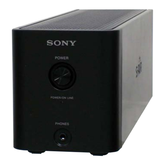
TA-SA100WR SECTION 2 This section is extracted GENERAL from instruction manual. Index to Parts Surround amplifier Front panel Rear panel EZW-RT POWER S-AIR ID SPEAKER POWER/ON LINE PAIRING PHONES SURROUND SELECTOR SURROUND SURROUND BACK A PHONES jack B POWER button (ON/OFF) -
Page 7: Disassembly
TA-SA100WR SECTION 3 DISASSEMBLY • This set can be disassembled in the order shown below. 3-1. DISASSEMBLY FLOW 3-2. COVER (CORD) (Page 7) 3-3. CASE (Page 8) 3-4. SHIELD (TOP), POWER CORD (Page 8) 3-5. POWER SW BOARD, PANEL BOARD, FRONT PANEL BLOCK 3-6. -
Page 8: Shield (Top), Power Cord
TA-SA100WR 3-3. CASE case four claws four claws screw (BVTT3 × 6) screw (BVTT3 × 6) 3-4. SHIELD (TOP), POWER CORD two screws (BV3) two screws (BV3) four screws (BV3) two screws (BV3) two screws (BV3) shield (top) cord bushing... -
Page 9: Power Sw Board, Panel Board, Front Panel Block
TA-SA100WR 3-5. POWER SW BOARD, PANEL BOARD, FRONT PANEL BLOCK 3-7. POWER BLOCK shield (front) two screws four screws (BV3) connector (BVTP2.6) (CN301) POWER SW board PANEL board two screws (BV3) power block bracket (button) spring (button) button (power) two connectors... -
Page 10: Diagrams
TA-SA100WR SECTION 4 DIAGRAMS 4-1. BLOCK DIAGRAM STREAM PROCESSOR IC300 • SIGNAL PATH : AUDIO DIND_DOUTB DATA TB300 POWER DRIVER SPEAKER IC100 LRCK LRCK 36 XFSIIN 6 PWM_A 28 – 30 (–) OUTL1 OUT_A D-FLIP-FLOP OUTL2 14 PWM_B OUT_B 25 – 27... - Page 11 TA-SA100WR Ver. 1.2 THIS NOTE IS COMMON FOR PRINTED WIRING BOARDS AND SCHEMATIC DIAGRAMS. • Circuit Boards Location (In addition to this, the necessary note is printed in each block.) JOINT board For Printed Wiring Boards. For Schematic Diagrams. Note:...
-
Page 12: Amp Board (Component Side) (Suffi X-11)
TA-SA100WR 4-2. PRINTED WIRING BOARD - AMP Board (Component Side) (Suffi x-11) - • See page 11 for Circuit Boards Location. • : Uses unleaded solder. AMP BOARD (COMPONENT SIDE) JOINT BOARD CN507 (Page 18) IC502 C575 X300 Q580 (11) 1-875-376- •... -
Page 13: Amp Board (Conductor Side) (Suffi X-11)
TA-SA100WR 4-3. PRINTED WIRING BOARD - AMP Board (Conductor Side) (Suffi x-11) - • See page 11 for Circuit Boards Location. • : Uses unleaded solder. POWER BOARD (Page 20) AMP BOARD (CONDUCTOR SIDE) CN904 (NC) D352 SP TERM MODE SW... - Page 14 TA-SA100WR 4-4. PRINTED WIRING BOARD - AMP Board (Component Side) (Suffi x-12) - • See page 11 for Circuit Boards Location. • : Uses unleaded solder. AMP BOARD (COMPONENT SIDE) JOINT BOARD CN507 (Page 18) IC502 C575 X300 Q580 (12) 1-875-376- •...
- Page 15 TA-SA100WR 4-5. PRINTED WIRING BOARD - AMP Board (Conductor Side) (Suffi x-12) - • See page 11 for Circuit Boards Location. • : Uses unleaded solder. POWER BOARD (Page 20) AMP BOARD (CONDUCTOR SIDE) CN904 (NC) D352 SP TERM MODE SW...
-
Page 16: Schematic Diagram - Amp Board (1/2)
TA-SA100WR 4-6. SCHEMATIC DIAGRAM - AMP Board (1/2) - • See page 11 for waveforms. • See page 22 for IC Block Diagrams. • See page 24 for IC Pin Function Description. CN500 AMP BOARD (1/2) R528 100 R513 (Suffix-11) - Page 17 TA-SA100WR 4-7. SCHEMATIC DIAGRAM - AMP Board (2/2) - • See page 11 for waveforms. • See page 22 for IC Block Diagrams. AMP BOARD (2/2) R107 R109 R108 100k 100k 100k R207 100k R209 100k R208 100k Q100, 101...
-
Page 18: Printed Wiring Boards - Panel Section
TA-SA100WR Ver. 1.1 4-8. PRINTED WIRING BOARDS - PANEL Section - • See page 11 for Circuit Boards Location. • : Uses unleaded solder. JOINT BOARD (COMPONENT SIDE) JOINT BOARD (CONDUCTOR SIDE) FB540 R602 CN507 CN508 C520 11,12 11,12 R601... -
Page 19: Schematic Diagram - Panel Section
TA-SA100WR 4-9. SCHEMATIC DIAGRAM - PANEL Section - JOINT BOARD SP TERM BOARD CN508 CN302 EZW-RT10 SR(+) CN507 TB300 VCC_3.3V SPEAKERS SR(-) C520 BOARD (2/2) SL(+) CN300 SL(-) (Page 17) GPIO2_ASIC_INT GPIO2 GPIO3_ASIC R601 GPIO1 GPIO0_ASIC R602 RESEN WIRELESS (CHASSIS) -
Page 20: Printed Wiring Boards - Power Section
TA-SA100WR Ver. 1.2 4-10. PRINTED WIRING BOARDS - POWER Section - • See page 11 for Circuit Boards Location. • : Uses unleaded solder. AEP, RU, UK, E3, E15, POWER BOARD E32, EA, SP, KR, TH, AUS FR901 C920 (EXCEPT E32, MX) -
Page 21: Schematic Diagram - Power Section
TA-SA100WR Ver. 1.2 4-11. SCHEMATIC DIAGRAM - POWER Section - • See page 22 for IC Block Diagrams. POWER BOARD ∗ R917,922 33k(US,CND,MX,TW) AEP,RU,UK,E3,E15, F901 E32,EA,SP,KR,TH,AUS 5A/125V(US,CND,MX,TW) PC902 ∗ C902 T3.15AH/250V(AEP,RU,UK,E3,E15,EA,SP,KR,TH,AUS) PS2561AL1-1-V-W 470p 250V(AEP,RU,UK,E3,E15,EA,SP,KR,TH,AUS) D911 T5AH/250V(E32) R917 R922 ISOLATOR 0.001 250V(US,CND,TW) 10EDB60-TA2B5 ∗... - Page 22 TA-SA100WR • IC Block Diagrams – AMP Board – IC100, 200 CXD9883M IC300 CXD9843AR BST_A PVDD_A Over Current Fault GVDD_A PVDD_A /OTW VREG PVDD_A Gate Drive /HIZ_HS_A PGND /HIZ_LS_A Stuck Detect /RESET PGND Protection Logic CLOCK CLOCK Timing PWM_A PGND...
- Page 23 TA-SA100WR Ver. 1.1 IC501 PST3629NR OUT 1 VDD 2 – VREF GND 3 – POWER Board – IC901 STR-W6735N (US, CND, MX, TW), STR-W6765N (AEP, RU, UK, E3, E15, E32, SP, KR, TH, AUS) DRIVE REGULATOR REGULATOR PROTECTION START/STOP & ICONST –...
- Page 24 TA-SA100WR • IC Pin Function Description AMP BOARD IC500 R5F3640DDFAR-128 (SURROUND AMP CONTROLLER) Pin No. Pin Name Description 1 to 3 NO USE Not used SIRCS_IN Sircs signal input terminal (for debug) 5 to 7 NO USE Not used BYTE External data bus input terminal Fixed at "L"...
- Page 25 TA-SA100WR Pin No. Pin Name Description 77, 78 NO USE Not used S-AIR_RESET S-AIR reset signal output to the EZW-RT10 "L": reset NO USE Not used EEP_WP Write protect signal output to the EEPROM "H": protect EEP_SCL Serial clock signal input/output with the EEPROM...
-
Page 26: Exploded Views
TA-SA100WR Ver. 1.2 SECTION 5 EXPLODED VIEWS Note: • -XX and -X mean standardized parts, so • Accessories are given in the last of the The components identifi ed by mark 0 they may have some difference from the electrical parts list. - Page 27 TA-SA100WR Ver. 1.2 5-2. TOP SHEILD SECTION not supplied chassis section front panel section Ref. No. Part No. Description Remark Ref. No. Part No. Description Remark 3-077-331-21 +BV3 (3-CR) 0 52 1-834-978-11 CORD, POWER (US, CND, MX) 0 52 1-769-079-61...
-
Page 28: Front Panel Section
TA-SA100WR Ver. 1.2 5-3. FRONT PANEL SECTION not supplied not supplied (POWER SW board) not supplied not supplied not supplied (PANEL board) Note: The front panel (Ref.No.101) and the power indicator (Ref. No.104) are welded. Please exchange both at the same time when you exchange the front panel or the power indicators. -
Page 29: Chassis Section
TA-SA100WR 5-4. CHASSIS SECTION not supplied not supplied (JOINT board) not supplied not supplied not supplied power section not supplied (LED board) not supplied not supplied not supplied not supplied not supplied Note: If wire (fl at type) is replaced, install it after bending it in the same from as that before replacement. -
Page 30: Power Section
TA-SA100WR Ver. 1.2 5-5. POWER SECTION not supplied not supplied (SP TERM board) not supplied (MODE SW board) (US, CND, E32, MX, TW) supplied F901 not supplied not supplied Ref. No. Part No. Description Remark Ref. No. Part No. Description... -
Page 31: Electrical Parts List
TA-SA100WR Ver. 1.3 SECTION 6 ELECTRICAL PARTS LIST Note: • Due to standardization, replacements in • SEMICONDUCTORS When indicating parts by reference num- the parts list may be different from the In each case, u: μ, for example: ber, please include the board name. - Page 32 TA-SA100WR Ref. No. Part No. Description Remark Ref. No. Part No. Description Remark C433 1-104-658-91 ELECT 100uF IC404 6-712-615-01 IC SI-3120KM-TLS C434 1-162-970-11 CERAMIC CHIP 0.01uF IC500 A-1545-410-A IC R5F3640DDFAR-128 (for SERVICE) C440 1-126-933-11 ELECT 100uF IC501 6-701-680-01 IC PST3629NR...
- Page 33 TA-SA100WR Ref. No. Part No. Description Remark Ref. No. Part No. Description Remark R206 1-216-835-11 METAL CHIP 1/10W R506 1-216-821-11 METAL CHIP 1/10W R207 1-216-845-11 METAL CHIP 100K 1/10W R507 1-216-833-11 METAL CHIP 1/10W R208 1-216-845-11 METAL CHIP 100K 1/10W...
- Page 34 TA-SA100WR Ver. 1.2 JOINT MODE SW PANEL POWER Ref. No. Part No. Description Remark Ref. No. Part No. Description Remark JOINT BOARD < FERRITE BEAD > *********** FB185 1-500-236-22 BEAD, FERRITE (CHIP) (1608) < CAPACITOR > FB285 1-500-236-22 BEAD, FERRITE (CHIP) (1608)
- Page 35 TA-SA100WR Ver. 1.2 POWER Ref. No. Part No. Description Remark Ref. No. Part No. Description Remark C931 1-128-959-21 ELECT 1000uF 0 R905 1-215-902-51 METAL OXIDE C932 1-115-339-11 CERAMIC CHIP 0.1uF (US, CND, MX, TW) 0 R905 1-218-642-51 METAL OXIDE 100K...
- Page 36 TA-SA100WR Ver. 1.2 POWER SW SP TERM Ref. No. Part No. Description Remark POWER SW BOARD **************** < CONNECTOR > 0 CN905 1-695-044-11 PIN, CONNECTOR (3.96mm PITCH) 2P 0 CN906 1-695-044-11 PIN, CONNECTOR (3.96mm PITCH) 2P < SWITCH > 0 S901...
- Page 37 TA-SA100WR MEMO...
- Page 38 TA-SA100WR REVISION HISTORY Checking the version allows you to jump to the revised page. Also, clicking the version at the top of the revised page allows you to jump to the next revised page. Ver. Date Description of Revision 2008.02 2008.04...
Need help?
Do you have a question about the TA-SA100WR and is the answer not in the manual?
Questions and answers