Table of Contents
Advertisement
Quick Links
Advertisement
Table of Contents

Subscribe to Our Youtube Channel
Related Manuals for Enovation Controls MURPHY PowerView


Summary of Contents for Enovation Controls MURPHY PowerView
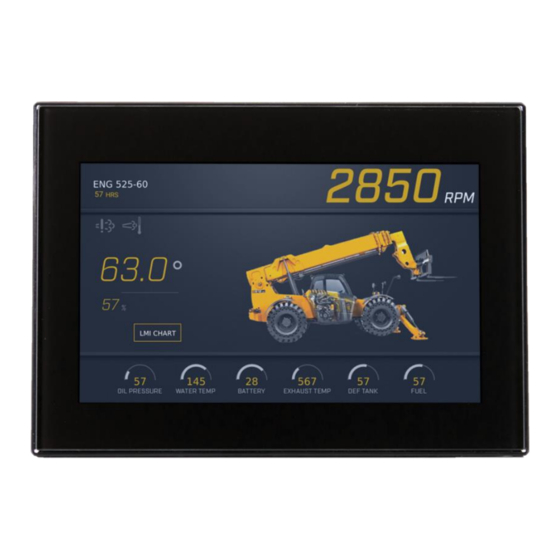
- Page 1 PowerView ® Model PV700 Installation Manual 00-02-1181 2019-10-12 Section 78...
- Page 2 BEFORE BEGINNING INSTALLATION OF THIS MURPHY PRODUCT: Read and follow all installation instructions. Please contact Enovation Controls immediately if you have any questions. This product can expose you to chemicals including lead, which is known to the State of California to cause cancer. For more information,...
-
Page 3: Table Of Contents
Table of Contents Hardware Installation ........................3 Inspecting Package Contents ..................3 Surface-Mounted Installation ..................3 Preparing the Dash ..................... 4 Surface-Mounting the Unit ..................4 Flush-Mounted Installation (Actual Size) ................ 6 Flush-Mounting the Unit ....................7 Available Accessories for the PV700 ................. 7 Pinout Specifications ........................ - Page 4 THIS PAGE INTENTIONALLY LEFT BLANK...
-
Page 5: Hardware Installation
Hardware Installation The following instructions will guide you through installing the PowerView display. Inspecting Package Contents Before attempting to install the product, it is recommended that you ensure all parts are accounted for and inspect each item for damage (which sometimes occurs during shipping). The items included in the box are: •... -
Page 6: Preparing The Dash
Installation Kit – P/N 78051451 includes • Mounting Bracket • Gasket/Panel Seal • Seven #8 washers • Seven 8-32 machine screws • Seven 10-32 nuts 3/8” • Six 10-32 1-3/4” machine screws Tools needed. • Drill with 7/32 in. size bit •... - Page 7 Surface Mount (Actual Size)
-
Page 8: Flush-Mounted Installation (Actual Size)
Flush-Mounted Installation (Actual Size) -
Page 9: Flush-Mounting The Unit
5. Hand-tighten the screws to draw the display tight against the panel. 6. Torque to 3 inch-pounds then tighten locking nuts. Available Accessories for the PV700 The following PV700 accessories are available through Enovation Controls: Part Number Description Order Details... -
Page 10: Pinout Specifications
Pinout Specifications Standard Version Black Connector Digital Input 1 Analog Input 3 + Analog Input 2 + Analog Input 1 + CAN1 Low CAN1 High Battery Ground Analog Input 3 - Analog Input 2 - Mating Connector AMP 770680-1 Analog Input 1 - Digital Input 3 Digital Input 2 Frequency Output 1... - Page 11 Blue Connector Frequency In Video 4 In P Video 3 In P Video 2 in P Video 1 in P Frequency In Return Mating Connector 12V Output AMP 770680-5 Video 4 In N Video 3 in N Video 2 In N Video 1 In N...
- Page 12 Ethernet (M12) Connector Ethernet TX+ Ethernet RX+ Ethernet TX- Ethernet RX- Ethernet Ground M-12, 5-pos, A-coded, Plastic Knurl Connector Only 3Pin D code M12 Connector D12D – S103SN Pigtail Options Radio Antenna (Optional) Aux Input (Optional)
-
Page 13: Configuration Information
Configuration Information Follow these steps to download a custom configuration to the PV700 display: Step Action Turn off the display. Insert the USB drive that contains the new configuration file into the display’s attached USB pigtail. Place a magnet into the notch shown here on the upper middle side of the back of the display: Power the display back on, continually holding the magnet in place. -
Page 14: Specifications
Specifications Computing Processor: Renesas R-Car M2 with Arm Cortex-A15 dual core processor @ 1.5 GHz (32-bit) ® Storage: 8 GB flash memory Ram: 512 MB DDR3-SDRAM Display 7” (178mm) LED backlight LVDS TFT LCD 16-bit color Type: Resolution: WVGA, 800 x 480 pixels Contrast Ratio: 600:1 (typical) Brightness:... -
Page 15: Dimensions
(1) 500 mA Switched Low-side Outputs: (2) Frequency Out (2Hz – 3kHz) (3) Analog 0-5 VDC, 4-20 mA, or resistive, 10-bit resolution Inputs: (5) Discrete digital, active-low, switch to ground, 20mA wetting current (1) Frequency In (0.5Hz – 20kHz) 5V offset, 2VAC to 120VAC Environmental Operating and -40°C to +85°C (-40°F to +185°F)
Need help?
Do you have a question about the MURPHY PowerView and is the answer not in the manual?
Questions and answers