Table of Contents
Advertisement
Quick Links
Advertisement
Table of Contents

Subscribe to Our Youtube Channel
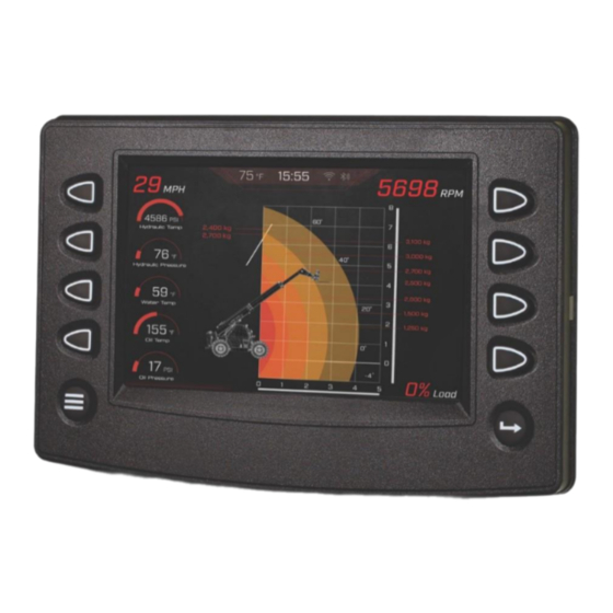
Summary of Contents for Enovation Controls MURPHY PowerView PV780B
- Page 1 ® PowerView Model PV780B Installation Manual 00-02-1019 2023-06-12 Section 78...
- Page 2 The latest version of this manual can be found at enovationcontrols.com. Please read the following information before installing. BEFORE BEGINNING INSTALLATION OF THIS MURPHY PRODUCT: Read and follow all installation instructions. Please contact Enovation Controls immediately if you have any questions.
-
Page 3: Table Of Contents
Table of Contents Hardware Installation ........................5 Inspecting Package Contents ..................... 5 PV780 Bracket for RAM Mount Option ....................7 RAM Mount Options for PV780B ......................7 Wiring Information ........................9 Pin Out Specifications ......................9 Configuration Information ......................11 Wiring Schematics –... - Page 4 THIS PAGE INTENTIONALLY LEFT BLANK...
-
Page 5: Hardware Installation
NOTE: When using the paper template from the manual, if you downloaded this document from the Enovation Controls website, be aware that the pdf file may not automatically print to scale. When submitting the file for print, you will need to select None for Page Scaling. - Page 6 Mounting the Unit 1. Place the back side of the display through the opening in the dash. 2. Use the four screws to line up the unit with the drilled holes. 3. Push the unit through the opening and screws through the drilled holes until the back of the case is flush.
-
Page 7: Pv780 Bracket For Ram Mount Option
PV780 Bracket for RAM Mount Option Part Number Description Order Details Bracket and Screw Kit for PV780B Display Call your regional sales 78001053 (RAM mount not included) office or account manager. RAM™ Mounts The following mount accessories may be used with our Bracket and Screw Kit “78001053”. - Page 8 Bracket Mounting Assembly Mounting with Kit # 78001295 Available Accessories for the PV780B The following PV780B accessories are available through Enovation Controls: Part Number Description Order Details 78090098 Programming Kit, PV780 78051181 Cover, PV780 78001053 Bracket Kit (screws included) 78001055...
-
Page 9: Wiring Information
Wiring Information Pin Out Specifications Right Connector Digital Input 1 Analog Input 3 Analog Input 2 Analog Input 1 CAN1 Low CAN1 High Battery Ground Analog Input 3 Ground Analog Input 2 Ground Analog Input 1 Ground Digital Input 3 Digital Input 2 Frequency Output 1 Ignition Input... - Page 10 Left Connector Video Input 1 Video Input 2 Video Input 3 RS-485 High RS-485 Low No Connect No Connect No Connect Video Input 1 Ground Video Input 2 Ground Video Input 3 Ground No Connect Frequency Input Frequency Return No Connect USB D- USB D+ USB 5V...
-
Page 11: Configuration Information
Ethernet (M12) Connector Ethernet TX+ Ethernet RX+ Ethernet TX- M-12, 5-pos, A-coded, Ethernet RX- Plastic Knurl Connector Only Ethernet Ground NOTE: Ethernet connectivity is optional. Configuration Information Follow these steps to download a custom configuration to the PV780B display: Step Action Ensure that PowerVision is open on your computer. - Page 12 Follow these steps to download a custom configuration using a USB drive: Step Action Create your custom configuration file within PowerVision. Save the file to a USB drive. Connect the USB drive to the USB port on the pigtail or on the USB on-the-go connector provided with the programming kit.
-
Page 13: Wiring Schematics - Right Connector
Wiring Schematics – Right Connector WARNING: Failure to install the unit per the specified wiring diagrams may cause damage to the unit. DO NOT connect power to the video ground. Warranty is void for damage caused by incorrect wiring. Section 78 - 13 - 00-02-1019 2023-06-12... -
Page 14: Wiring Schematics - Left Connector
Wiring Schematics – Left Connector WARNING: Failure to install the unit per the specified wiring diagrams may cause damage to the unit. DO NOT connect power to the video ground. Warranty is void for damage caused by incorrect wiring. Section 78 - 14 - 00-02-1019 2023-06-12... -
Page 15: Specifications
Specifications Computing Main Processor: Renesas R-Car M2, 32-Bit Arm Cortex A15 Processor @ 1.5 GHz ® Operating Sys: Real-time Operating System Storage: 8GB Flash memory for Operating System, Application and Configuration Ram: 512 Mb DDR3-SDRAM Graphics: Renesas graphics processor Displays 7”... -
Page 16: Dimensions
Electrical Operating Volts: 6-36 VDC, Reverse polarity protected 11W @ 12V with Full Backlight Power 13W @ 24V with Full Backlight Consumption: (1) 500 mA Switched Low-side Outputs: (1) Frequency Output (2Hz – 3KHz) (3) Analog 0-5 VDC, 4-20mA, Resistive, 10-bit resolution Inputs: (5) Discrete digital, active high (1) Frequency In (2Hz –... - Page 17 Section 78 - 17 - 00-02-1019 2023-06-12...


Need help?
Do you have a question about the MURPHY PowerView PV780B and is the answer not in the manual?
Questions and answers