Table of Contents
Advertisement
Advertisement
Table of Contents

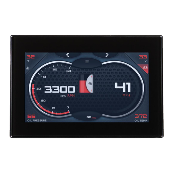
Summary of Contents for Enovation Controls MURPHY PowerView PV500
- Page 1 ® PowerView Model PV500 Installation Manual 00-02-1183 2019-11-21 Section 78...
- Page 2 BEFORE BEGINNING INSTALLATION OF THIS MURPHY PRODUCT: Read and follow all installation instructions. Please contact Enovation Controls immediately if you have any questions. This product can expose you to chemicals including lead, which is known to the State of California to cause cancer. For more information, go to www.P65Warnings.ca.gov.
-
Page 3: Table Of Contents
Table of Contents Hardware Installation ......................... 4 Inspecting Package Contents ..................4 Surface-Mounted Installation ..................4 Preparing the Dash ....................5 Surface-Mounting the Unit ..................7 Flush-Mounted Installation: ..................7 Flush-Mounting the Unit ................... 9 Available Accessories for the PV500 ................9 Pinout Specifications ......................10 Standard Version ....................... - Page 4 THIS PAGE INTENTIONALLY LEFT BLANK Section 78 - iii - 00-02-1183 2019-11-21...
-
Page 6: Hardware Installation
Hardware Installation The following instructions will guide you through installing the PowerView display. Inspecting Package Contents Before attempting to install the product, it is recommended that you ensure all parts are accounted for and inspect each item for damage (which sometimes occurs during shipping). The items included in the box are: ... -
Page 7: Preparing The Dash
Installation Kit – P/N 78051705 includes Mounting Bracket Five 8-32 machine screws Five 10-32 1-3/4” machine screws Five 10-32 3/8”nuts Five #8 washers Tools needed. Drill with 7/32 in. size bit Jigsaw Screw Driver Preparing the Dash Determine the location of the PV500 in the dash. - Page 8 Section 78 - 6 - 00-02-1183 2019-11-21...
-
Page 9: Surface-Mounting The Unit
Surface-Mounting the Unit 1. Place the back side of the display through the opening so the display will sit on the face of the dash. 2. Use the included four long screws and locking nuts from the mounting kit (78051705) to attach the unit to the bracket. - Page 10 Section 78 - 8 - 00-02-1183 2019-11-21...
-
Page 11: Flush-Mounting The Unit
3. Use the included four long screws and four locking nuts from the mounting kit (78051705) to attach the unit to the bracket. 4. Torque to 10 inch-pounds. Available Accessories for the PV500 The following PV500 accessories are available through Enovation Controls: Part Number Description Order Details... -
Page 12: Pinout Specifications
Pinout Specifications Standard Version Section 78 - 10 - 00-02-1183 2019-11-21... -
Page 13: Configuration Information
Configuration Information Follow these steps to download a custom configuration to the PV500 display: Step Action Turn off the display. Insert the USB harness 78000668 into Port A of the display. Then insert a USB drive that contains the new configuration file into the USB connector on that harness. -
Page 14: Specifications
Specifications Computing Main Processor: Renesas RZ/G1E Arm Cortex-A7 Dual core processor @ 1.0 GHz Operating System: QNX® Real-time Operating System Storage: 8 GB Ram: 256 MB Display 5” (108mm [H] x 64.8mm [W]) 24-bit LED backlight LCD Type: Resolution: 800 x 480 pixels Contrast Ratio: 1000:1 (typical) Brightness:... - Page 15 Electrical 6 – 36 VDC, reverse polarity protected. Max current draw @ 12 V: 0.438A Operating Voltage: Min current draw @ 12 V: 0.318A Max current draw @ 24 V: 0.297A Min current draw @ 24 V: 0.202A Outputs: (1) 500 mA Switched Low-side (1) Analog 0-5 VDC, 4-20 mA, or resistive, 10-bit resolution Inputs: (2) Discrete digital, active-high...
-
Page 16: Dimensions
Dimensions Part # 78051705 Mounting Bracket Section 78 - 14 - 00-02-1183 2019-11-21... - Page 17 Section 78 - 15 - 00-02-1183 2019-11-21...


Need help?
Do you have a question about the MURPHY PowerView PV500 and is the answer not in the manual?
Questions and answers