
Related Manuals for Enovation Controls Murphy PowerView PV101-C


Summary of Contents for Enovation Controls Murphy PowerView PV101-C
- Page 1 PowerView Model PV101-C User’s Guide Version 3.2 2013-04-08 00-02-0796 Catalog Section 78...
-
Page 3: Table Of Contents
Table of Contents Introduction ................1 Engine and Transmission Parameters ..............2 Faceplate Features ....................3 Navigation and Keypad Functions ................4 First Time Start Up ..............8 Main Menu Options ..............11 Go to 1-Up Display/Go to 4-Up Display ..............11 DPF Regen* ...................... - Page 4 OEM Menu ................27 MODBUS Setup ....................27 CANBUS Data Rate ....................28 Select Engine ECU ....................29 Set Source Address ....................30 Restore All Defaults ....................30 Clear Machine Hours .................... 30 Set Machine Hours ....................30 Fuel Setpoints ....................... 31 DPF Regen Menu ON/OFF ...................
- Page 5 The latest version of this manual can be found at www.fwmurphy.com. Warranty - A limited warranty on materials and workmanship is given with this Enovation Controls product. A copy of the warranty may be viewed or printed by going to www.fwmurphy.com/warranty...
- Page 6 BEFORE BEGINNING INSTALLATION OF THIS MURPHY PRODUCT: • Disconnect all electrical power to the machine. • Make sure the machine cannot operate during installation. • Follow all safety warnings of the machine manufacturer. • Read and follow all installation instructions.
-
Page 7: Introduction
Introduction Congratulations on purchasing your PowerView display, a multifunction tool that provides a window into the many parameters and service codes of modern electronic engines and transmissions. This guide is intended to help you set up your PowerView display and identify navigation basics and product features. The display’s simple navigation and powerful features allow you to quickly master the product. -
Page 8: Engine And Transmission Parameters
Engine and Transmission Parameters The following are some of the engine and transmission parameters which can be displayed in standard or metric units as well as in English, Spanish, French, Italian or German languages (when applicable, consult engine or transmission manufacturer for SAE J1939 supported parameters): •... -
Page 9: Faceplate Features
Faceplate Features 00-02-0796 - 3 - 2013-04-08... -
Page 10: Navigation And Keypad Functions
Navigation and Keypad Functions The keypad on the PowerView display is a capacitive touch sensing system. There are no mechanical switches to wear or stick. The keys on the keypad perform the following functions: Menu – Enter or exit menu screens. Left Arrow –... - Page 11 Basic Navigation 1. When Menu is pressed, the Main menu items display. 2. Press the Arrow Keys to move the selection bar to other menu items. 00-02-0796 - 5 - 2013-04-08...
- Page 12 3. Certain menus have multiple pages. Scrolling to the top or bottom item on the current page reveals other menu items on additional pages. 00-02-0796 - 6 - 2013-04-08...
- Page 13 When the desired item is highlighted by the cursor, pressing Enter selects that item and displays the corresponding screen. 00-02-0796 - 7 - 2013-04-08...
-
Page 14: First Time Start Up
First Time Start Up When power is first applied to the display, the Murphy logo is displayed. NOTE: Expect a 20-minute warm up for the display at temperatures of C/-20 00-02-0796 - 8 - 2013-04-08... - Page 15 If the Engine ECU is broadcasting a ‘Wait to Start' message, this screen will be shown. Engine manufacturers typically recommend against starting the engine while this message is broadcasted from the ECU. Once the ECU stops broadcasting this message, this screen will no longer be displayed. 00-02-0796 - 9 - 2013-04-08...
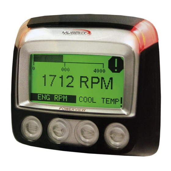
- Page 16 3. Once the engine has started, the single engine parameter is displayed with the engine RPM. Touching the Right Arrow Key displays the coolant temperature. The screen can be changed to other parameters by touching Menu. 00-02-0796 - 10 - 2013-04-08...
-
Page 17: Main Menu Options
Main Menu Options This section describes the features listed on the Main menu of the PowerView. These menu options display whenever you touch Menu. The Arrow Keys allow you to scroll through items. Enter selects the highlighted option. Go to 1-Up Display/Go to 4-Up Display If you want to go to a different display, touch Enter. - Page 18 1. AUTO DPF REGEN – This is the factory default. Select and PowerView sends a CAN message to the ECU to perform DPF Regeneration (regen) automatically whenever needed. 2. REQUEST DPF REGEN – Select this and a second screen, REQUEST DIESEL PARTICULATE FILTER REGEN, displays.
-
Page 19: Selecting A Language
The following ISO symbols indicate regen status. In each case, the symbol displays when the parameter’s lamp status is broadcast from the ECU back to the PowerView. DPF Regen ISO Symbols Icon Description High Exhaust Temperature 64892 3697 (HEST) lamp indicates regeneration in process. -
Page 20: Stored Codes
Stored Codes Select this and PowerView requests and displays stored fault codes from the engine ECU. If the engine does not support this function, a “Timeout ECU Not Responding” message displays. Engine Configuration This allows you to scroll through and view the engine’s configuration data. - Page 21 To select USE DEFAULTS, highlight the option and press Enter. A message indicating “RESTORED TO DEFAULTS” is displayed. 2. Custom Setup – In this option, select the parameters and order in which they will be displayed. The list is long; continue to scroll until you have seen all available parameters.
- Page 22 Continue to scroll and select additional parameters for the CUSTOM 1-UP DISPLAY. Touch Menu at any time to return to the CUSTOM SETUP menu. 3. Automatic Scan – (Default is OFF) Selecting the AUTOMATIC SCAN ON function will cause the 1-up display to scroll through the selected set of parameters one at a time.
-
Page 23: Setup 4-Up Display
Setup 4-Up Display There are two 4-up display screens available. Each option can place parameter data into one of four areas on the screen known as quadrants. ▪ Factory defaults for the first 4-up display include coolant temperature, engine speed, oil pressure, and battery voltage. - Page 24 4. Use the Arrow Keys to switch between the two 4-up displays. 5. To edit a 4-up display, touch Enter while that 4-up displays on screen. 6. Use the Arrow Keys to select which quadrant to edit. 7. Once you select a quadrant, press Enter and you move to a list of parameters.
- Page 25 1 = upper left 3 = upper right quadrant quadrant 2 = lower left 4 = lower right quadrant quadrant 9. Use the Arrow Keys to highlight the new parameter to be placed in the selected quadrant. Touch Enter. 10. Press Menu to return to the SETUP 4-UP CUSTOM SETUP screen.
-
Page 26: Service Reminders
Service Reminders SERVICE REMINDERS permit you to RESET REMINDERS or MODIFY REMINDERS for changing engine oil, air filters, and hydraulic oil or for servicing the engine and/or machine. NOTE: Service Reminders are internal reminders within PowerView. Once a Service Reminder is active, warnings will show SPN 916 and FMI 17. - Page 27 5. If you select Modify Reminders, use the Arrow Keys to highlight the Reminder to modify and touch Enter. 6. The Reminder name appears at top screen. The hour value displays mid-screen and allows you to set the number of hours to elapse before a Reminder prompts. Bottom screen shows Cancel and Save.
-
Page 28: Select Units
Select Units From SELECT UNITS, you may select how information is displayed: ▪ ENGLISH for Imperial units (PSI, °F) ▪ METRIC KPA ▪ METRIC BAR for IS units (kPa, Bar, °C). Backlight Adjustment ADJUST BACKLIGHT – Use the Arrow Keys to brighten or darken the backlight intensity. -
Page 29: Utilities Menu
Utilities Menu UTILITIES is the last item on the Main Menu. The Utilities menu provides troubleshooting features and other information about the PowerView configuration. Gage Data View data for optional connected PVA gages. When Slave Active is enabled, gage data is not available. Remove All Gages Reset the gage memory on the PowerView. -
Page 30: Fault Conversion
Fault Conversion View/Edit the J1939 fault code version. Use the Arrow Keys to move between Versions, and then touch Enter to select a version. NOTE: There are four methods for converting fault codes. The PowerView always looks for J1939-Version However, PowerView can be set to read one of three other J1939 versions, if Version 4 is not used/unavailable. -
Page 31: Analog Input
Analog Input With Analog Input highlighted, press Enter. You can select between two settings: 1) BACKLIGHT DIMMER, this is in factory default upon first use. The unit accepts an optional backlighting dimmer (0-1k Ω potentiometer). 2) FUEL LEVEL, touch Enter to reach SET LOW FUEL LEVEL screen. - Page 32 1) From the Engine Speed Control screen, touch Enter to reach the Speed Control screen. 2) To change the setting of the engine speed via TSC1; use the right Arrow Key to increase or left Arrow key to decrease the throttle setting. 3) Once the target speed is reached, select ENABLE (Enter) to turn ON the TSC1 throttling control.
-
Page 33: Oem Menu
OEM Menu The OEM menu is the last item on the Utilities menu. You must have a password to access the OEM menu. Once in the OEM Menu, select an item by highlighting it and touch Enter to reach additional screens. ENTER PASSWORD screen –... -
Page 34: Canbus Data Rate
1) There are four selections: Use Factory Defaults, Serial Port Setup, Slave Address Setup, and Master Active/Slave Active. You can toggle between Slave Active (which is SCADA/remote Modbus master) and Master Active (which is Auxiliary gages). Highlight your selection and touch Enter. 2) If in Slave Active, select SERIAL PORT SETUP and touch Enter. -
Page 35: Select Engine Ecu
Select Engine ECU Highlight Select Engine ECU and touch Enter. 1) The message “LISTEN TO ECU: ALL” displays as the default setting. This message indicates the PV101 is listening to all devices on the network. 2) To change the setting to a specific address, press the Arrow Keys to scroll through the selections (0- 253, and ALL). -
Page 36: Set Source Address
Set Source Address Allows setting the source claim address for the PowerView on the CAN Network. Options are Auto Claim or 0 to 253. Restore All Defaults PowerView automatically resets after the restore defaults is complete. RESTORING ALL FACTORY DEFAULTS displays when this is selected. -
Page 37: Fuel Setpoints
Fuel Setpoints Highlight and press Enter to select Fuel Setpoints. 1) Press Enter to turn Fuel Setpoints ON or OFF. 2) Choose Set Empty Setpoint, Set Fuel Setpoint, Show Fuel Setpoints, Clear Fuel Setpoints, or choose to set ¼, ½ and ¾ fuel points. Fuel Setpoints must be ON to work with a non-Murphy fuel sender. -
Page 38: Eng Spd Ctrl Menu On/Off
ENG SPD CTRL Menu ON/OFF This option must be ON in the OEM Menu for functionality to be available in the Utilities Menu. Highlight and touch Enter. The Speed Control can be Enabled (ON) or Disabled (OFF). 00-02-0796 - 32 - 2013-04-08... -
Page 39: Faults And Warnings
Faults and Warnings The PowerView provides two means for detecting faults and warnings: visual LEDs on the casing (Amber in the upper left corner, and Red in the upper right corner) and fault indicators on the display. Visual Indication • Amber LED (Warning) •... -
Page 40: Auxiliary Gage Fault
Auxiliary Gage Fault Murphy PVA Gages can be attached to the PowerView. If an auxiliary gage should fail, the 1-up or 4-up display will be replaced with a fault message: GAGE NOT RESPONDING. NOTE: A fault can only be cleared by correcting the cause of the condition (See Troubleshooting in this document). -
Page 41: Derate / Shutdown Codes
Example: Active Fault Code screen Derate / Shutdown Codes When the PowerView receives a severe fault code from an engine control unit the 1-up or 4-up display is replaced with the SHUTDOWN message. 00-02-0796 - 35 - 2013-04-08... -
Page 42: Acknowledging Fault Codes
Acknowledging Fault Codes 1. To acknowledge and hide the fault and return to the 1-up or 4-up display, touch Enter. The display will return to the 1-up or 4-up display, but the display will contain the warning or shutdown icon. 2. -
Page 43: Troubleshooting
Troubleshooting WAIT TO START PREHEATING is displayed The ECU is broadcasting a 'Wait to Start' message. Engine manufacturers typically recommend against starting the engine while the ECU is broadcasting this message. Once the ECU stops broadcasting this message, this screen will no longer be displayed on the PowerView. - Page 44 NO STORED CODES is displayed The PowerView sent a request to the ECU for Stored Fault Code (DM2) information. The ECU responded: There are zero stored codes. NO GAGE DATA is displayed The PowerView has no record of gages connected to the RS485 bus.
- Page 45 DATA ERROR is displayed in place of a parameter value The ECU is sending a message that there is a data error with this parameter. Alternatively, (PV101 only) FUEL LEVEL has been selected for display, ANALOG INPUT has been set to FUEL LEVEL, but no Murphy Fuel Sender has been connected to the analog input.
- Page 46 IMPORTANT! Before returning your PV101 for Warranty, please call our Technical Support team to further trouble- shoot any issues. +1 (918) 317-4100 00-02-0796 - 40 - 2013-04-08...
- Page 47 NOTES 00-02-0796 - 41 - 2013-04-08...
- Page 48 NOTES...
- Page 49 NOTES...
- Page 50 Murphy, the Murphy logo, and PowerView are registered and/or common law trademarks of Enovation Controls, LLC. This document, including textual matter and illustrations, is copyright protected by © Enovation Controls, with all rights reserved. 2013 Enovation Controls, LLC. Other third party product or trade names referenced herein are the property of their respective owners and are used for identification purposes only.
-
Page 51: Additional Contact Information
Additional Contact Information ENOVATION ENOVATION CONTROLS – MURPHY INDUSTRIAL CONTROLS – SAN ANTONIO OFFICE PANEL DIVISION CORPORATE HQ 5757 Farinon Drive 5311 S. 122 East Ave. San Antonio, TX 78249 USA Tulsa, OK 74146 USA 5311 S. 122 East Ave. - Page 52 www.fwmurphy.com/PV101...
Need help?
Do you have a question about the Murphy PowerView PV101-C and is the answer not in the manual?
Questions and answers