Enovation Controls Murphy PowerView PV485 Operation Manual
Hide thumbs
Also See for Murphy PowerView PV485:
- Operation manual (53 pages) ,
- Operation manual (47 pages)

Subscribe to Our Youtube Channel
Related Manuals for Enovation Controls Murphy PowerView PV485


Summary of Contents for Enovation Controls Murphy PowerView PV485
- Page 1 ® PowerView Display Model PV485 Murphy Standard Operations Manual Deleted: 03 Deleted: 25 00-02-1207 2021-06-07 Section 78...
- Page 2 Please read the following information before installing. BEFORE BEGINNING INSTALLATION OF THIS MURPHY PRODUCT: • Read and follow all installation instructions. • Please contact Enovation Controls immediately if you have any questions. Deleted: Revision Date Deleted: 03 Deleted: 25 2021-06-07...
-
Page 4: Table Of Contents
Formatted Formatted Deleted: 33 Deleted: 37 Deleted: 41 Table of Contents Deleted: ¶ Deleted: Table of Contents Error! Bookmark not Introduction..........................Deleted: iii Engine Parameters ......................6 Deleted: ¶ Deleted: Introduction Error! Bookmark not defined.5¶ ... Glossary of Terms and Acronyms ................6 Deleted: 5 Button Assignments... - Page 5 THIS PAGE INTENTIONALLY LEFT BLANK Deleted: 03 Deleted: 25 2021-06-07 00-02-1207...
-
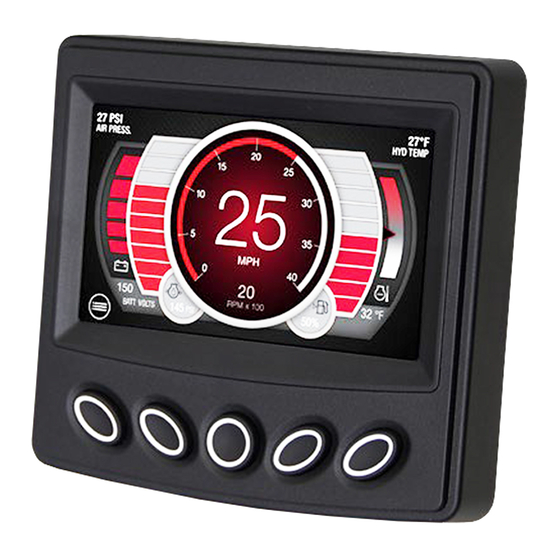
Page 6: Introduction
Introduction The PV485 is a rugged CAN-based controller. This manual explains the functions and display Deleted: describes the display screens screens of the unit, and gives details about the PV485 Murphy Standard Configuration. Engine Parameters The following are some of the 109 possible engine parameters that can be displayed in standard or metric units as well as in English, French, German, Spanish, Italian, Japanese, Chinese, Portuguese, Russian and Czech languages. -
Page 7: Button Assignments
Button Assignments button to determine that button’s function. Deleted: the Review the icon on the screen directly above each These functions change according to the screen that is displayed. In the above screen, Button 1 will provide the Password screen to enter the Main Menu. In other screens, Button 1 will serve a different function. -
Page 8: Button Functions
Button Functions The table below explains the button functions when they appear on the screen. Button Icon Description Go to menu password screen. Throttle or digital gauge value decrease Throttle or digital gauge value increase Start engine Stop engine Next / Enter Go to fault screen Go to preset screen Go to I/O status screen... -
Page 9: Regen Screen
Regen Screen Deleted: Pressing button 2 while Regen (as shown in the image above) is displayed will open the Deleted: the …utton 2 when Regen page, shown below. This provides the user control of engine regeneration and current Deleted: the “…r…gen”…(menu is a DPF status. -
Page 10: Preset Screen
Preset Screen Deleted: changed If Throttle Type is set in the Throttle menu to Preset, the context of main screen button #2 will change to “PRESET” as shown in the next image. Once you press the PRESET button, the preset speed options will appear as shown in the following image. -
Page 11: Alert Icons
Deleted: required Press the corresponding speed button to request the indicated speed, and back button to leave the page. Deleted: screen Alert Icons Deleted: are Red and The Alert Icons at the top of the main page will light up when communicating to the operator. Pay close attention to any Status Icon and its color that may appear. -
Page 12: Popup Message Screen
Status Icon Description Maintenance / Service Required Deleted: Check Engine / Protect Deleted: Parking Brake Engaged Deleted: Transmission Neutral Deleted: Stop engine. Deleted: Popup Message Screen Deleted: the When popup message shown, user must acknowledge pressing button 1 to cancel or button 5 to accept, then the popup message will clear. -
Page 13: Enter Password
Enter Password Step Action Adjust the highlighted number with the – (Button 2) and + (Button 4). Press Button 5 to move to the next number. Repeat steps 1 and 2 to assign all four numbers of the password, then press Button 3 to confirm. -
Page 14: Display Settings
• Display Settings • Engine Settings • System Settings • Advanced Settings • I/O Settings • Throttle Settings • Communication Setup • Diagnostics • Customize Display Interface • Main Screen Gauge Setup • Engine special functions (only available to specific engines) Pressing Button 5 will enter the selected menu area. - Page 15 Deleted: to Pressing button 3 again will clear the Tip screen. Deleted: ¶ Fault Popup Deleted: (message: need to needs¶ Deleted: will This selection allows the enabling or disabling of displaying faults screen pop up. If disabled, a warning icon will appear navigation bar above button 1 or 5 when...
- Page 16 Language Deleted: controls which language appears throughout the This selection selects the displayed language. Available languages include English, French, displaythe… German Spanish, Italian, Japanese, Chinese, Portuguese, Russian or Czech Deleted: ing Units This selection controls how measurements are displayed. Formatted: Centered Measurement Available Selections Formatted Table...
-
Page 17: Engine Settings
Step Action Select Display Settings, then Clock from the Main Menu. The next screen highlights the hour. Adjust this using Buttons 2 and/or 4. To move to the next field, press Button 5. Adjust the minutes. Press Button 5. Select between AM or PM. Press Button 5. (Optional Step) Change between 12HR and 24HR using Buttons 2 or 4. - Page 18 Engine Manufacturer Deleted: exists This selection allows the operator to select the engine manufacturer of the engine which currently includes: Caterpillar, Cummins, Deutz, JCB", Volvo, Perkins, HATZ, Yanmar, Kubota, Deleted: name Doosan, Kohler, John Deere, FPT, Isuzu, PSI, Ford, GM and Scania. By default, the engine Deleted: E...
-
Page 19: System Settings
Show Ash Gauge This selection determines whether the Optional Ash Gauge will be shown or hidden on the home screen. Show Soot Gauge This selection determines whether the Optional Soot Gauge will be shown or hidden on the home screen. Show Regen Progress This selection determines whether the progress during a Regeneration will be shown or hidden on the Regen... - Page 20 Clear Stored ECU Fault Codes Moved down [1]: Display will transmit clear Stored ECU allows the operator to clear stored faults from the engine ECU. This This selection Fault Codes CAN messages to request clear stored. ¶ setting should only be used by a qualified engine technician. All engine manufacturers Moved (insertion) [1] and models may not support this feature.
-
Page 21: Advanced Settings
Export Settings Deleted: either This selection allows exporting of established settings from menu within the display. This Deleted: or prohibits the feature is useful when the saved settings will be used on multiple displays. First ensure all settings are set then export to a USB using the programming kit (78700590), the programming Deleted: with the harness (78090077) or your own harness. - Page 22 ECU Source Address Deleted: a Allows the operator to set the source address to which the ECU will be connected. Deleted: of Normally set to 0, 1 or 2 per SAE J1939 specifications. Factory set to 0. Deleted: being connected to Deleted: This selection will set the ECU source address.
- Page 23 Menu Item Choices/Description Formatted: Indent: Left: 0" Enabled: The display will add the Count calculation to the transmitted TSC1 message. This requirement is common with Stage V engines. Calculate TSC1 Count Formatted Table Disabled: The display will not calculate Count and the Formatted: Indent: Left: 0"...
- Page 24 Moved up [7]: Enabled: display will transmit TSC1 Disabled: display will not transmit TSC1 messages. ¶ Shutdown and Warning TSC1 Independence (Enabled, Disabled)¶ Enabled: allows the user to set a separate source address for TSC1 throttling from the display’s claim address. This should only be done if the service technician knows this to be true.
-
Page 25: Io Settings
IO Settings This menu item controls the parameters for the: • Analog Inputs • Digital Inputs • Analog Outputs • Digital Deleted: and Outputs • Frequency Input Pulse. Analog Inputs Deleted: screen Analog Inputs 1 through 4 will display the following screen when selected: Step... - Page 26 Renaming Analog Inputs For each Analog Input, the option exists to Rename that input. Select Rename Analog Input (#) and the following screen will appear to create a different name. Use the buttons below the arrow keys to move the cursor along the keyboard. Select a letter and then press Button 3 to enter it.
- Page 27 Formatted: Indent: Left: -0.03" Park & Neutral Engine Idle Formatted: Indent: Left: -0.03" Preset Speeds 1, 2, 3 or 4 Formatted: Indent: Left: -0.03" Crank Abort Formatted: Indent: Left: -0.03" Active High Active State Formatted: Indent: Left: -0.03" Active Low Formatted: Font: Bold Analog Outputs Formatted: Indent: Left: -0.03"...
-
Page 28: Throttle Settings
Frequency Input Pulse This option allows the setting of the Frequency Input Pulse. Throttle Settings This menu item controls the parameters for the Throttle: • Throttle Type • Throttle Step • Maximum RPM Moved down [2]: <#>Throttle Method¶ • Idle RPM •... -
Page 29: Communication Setup
Knob Analog input is used as resistive when selected Deleted: Step Throttle Step Deleted: <#>J1939 TSC1 (operator can use this setting to throttle engine manually with display’s push buttons.)¶ This option controls the throttle increase/decrease step size between requested target engine Preset speed (operator can select preconfigured speed with displays’... - Page 30 • CAN termination resistor Modbus Baud Rate Deleted: s This menu item allows the operator to set the baud rate for Modbus communication. Default set to 38400 Kbps Deleted: the 2400 Kbps 4800 Kbps 9600 Kbps 19200 Kbps 38400 Kbps 57600 Kbps 115200 Kbps Modbus Stop Bits...
-
Page 31: Diagnostics
Modbus Slave Address Deleted: h This menu item allows the operator to set the Slave Address for Modbus communication. Deleted: sets Default to 1. Deleted: the CAN Baud Rate Deleted: sets This menu item allows the operator to set the Baud Rate for CAN communication. Default to 250Kbps Deleted: the... - Page 32 IO Status Deleted: multiple This menu item allows you to review the current IO status. It shows the pin number, pin name, Deleted: pages selected function, and status. See example screen below. Deleted: current status Modbus Register Deleted: , This menu item allows you to review all mapped Modbus registers, descriptions and live status.
- Page 33 RX CAN Recorder Deleted: is to make This menu item allows the operator create a received CAN traffic recording file and export Deleted: drive, which can later be used for analysis. The recorder will automatically record traffic for 10 seconds then export the file to USB drive.
-
Page 34: Customize Display Interface
Customize Display Interface Deleted: you This menu item allows the operator to change how the display presents engine information. Deleted: appears and • Main RPM gauge • Screen color • Reset default color • Upload splash image Main RPM Gauge Deleted: page This option... -
Page 35: Main Screen Gauge Setup
Moved (insertion) [4] Press Button 3 (RGBA) to move the highlight to change Red, Green, Blue, or Transparency Deleted: cursor to the color section. (Alpha) of the selected object. Deleted: Notice above, the cursor is around the red scale. Reset Default Color To return the display to its factory default color(s). - Page 36 Deleted: 03 Deleted: 25 2021-06-07 00-02-1207...
- Page 37 Gauge Groups 1 through 3 Deleted: 109 Each Gauge group will contain 4 gauges that will each be chosen from parameters. Formatted Table Accel Ped1 (SPN 91) Load@RPM (SPN 92) Actual Engine Torque (SPN 513) Engine RPM (SPN 190) Oil Level (SPN 98) Coolant Level (SPN 111) Alternator Voltage (SPN 167) System Voltage (SPN 168)
-
Page 38: Engine Manufacturer Specific Functions
Barometric Press (SPN 108) Aux Press (SPN 1387) Air Inlet Press (SPN 106) Hydraulic oil Press (SPN 1762) Fuel Rate (SPN 183) Instant Fuel Economy (SPN 184) Average fuel Economy (SPN 185) Fan Speed (SPN 1639) Vehicle Speed (SPN 84) Current Gear (SPN 523) Select Gear (SPN 524) Torque Lock (SPN 573) - Page 39 CAT or Perkins: Maintenance Reset will reset the Service infomation (SPN916). Deleted: I Alternative Low Idle can be used as a Lower Low Idle for prolonged idling period without Electrical Load or an elevated idle for fast warmup. When used as a Lower Low Idle, Deleted: I special attention is required on the current...
- Page 40 Kubota: Deleted: , Pump Learning is available on engines equipped with the Denso ECU. The display will automaticaly send pump learning settings to the engine ECU. Deleted: O Deleted: nly the Engine Control Mode Description Deleted: system needs to apply the pump learning Formatted: Font: Bold Droop Choosing Droop for Engine Control Mode is like a...
- Page 41 FPT: Formatted: Centered Menu Item Description Formatted: Font: Bold High Idle Speed Useful in working conditions where the application cannot run at a Formatted Table decrease natural engine high-idle speed. Here the operator can change the Formatted: Font: Bold speed setpoint. Low Idle Speed Useful in working conditions where the application cannot run at a increase...
-
Page 42: Wiring Instructions
Wiring Instructions PIN Specifications for AMPSEAL Style Connection Accessories P/N 78-00-0824 – Wiring Harness, Loose leads, 24 inches P/N 78-09-0077 – Programming Harness Deleted: 03 Deleted: 25 2021-06-07 00-02-1207... - Page 43 THIS PAGE INTENTIONALLY LEFT BLANK Deleted: 03 Deleted: 25 2021-06-07 00-02-1207...
- Page 44 THIS PAGE INTENTIONALLY LEFT BLANK Deleted: 03 Deleted: 25 2021-06-07 00-02-1207...
Need help?
Do you have a question about the Murphy PowerView PV485 and is the answer not in the manual?
Questions and answers