Enovation Controls MURPHY PowerView PV485 Operation Manual
Hide thumbs
Also See for MURPHY PowerView PV485:
- Operation manual (45 pages) ,
- Operation manual (53 pages)

Related Manuals for Enovation Controls MURPHY PowerView PV485


Summary of Contents for Enovation Controls MURPHY PowerView PV485
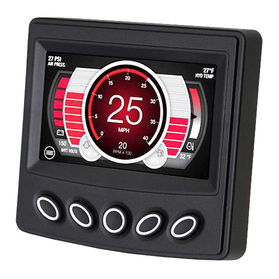
- Page 1 ® PowerView Display Model PV485 Murphy Standard Operations Manual 00-02-1207 2021-06-07 Section 78...
- Page 2 Please read the following information before installing. BEFORE BEGINNING INSTALLATION OF THIS MURPHY PRODUCT: • Read and follow all installation instructions. • Please contact Enovation Controls immediately if you have any questions. Revision Date Details 2022-12.22 Support for version 1.88...
-
Page 4: Table Of Contents
Table of Contents Introduction ............................. 6 Engine Parameters ......................6 Glossary of Terms and Acronyms................... 6 Button Assignments ...................... 7 Home Screen ........................7 Button Functions ......................8 Scrolling 12 Gauges ......................8 Regen Screen ........................9 I/O Status Screen ......................9 Preset Screen ........................ - Page 5 THIS PAGE INTENTIONALLY LEFT BLANK 2021-06-07 00-02-1207...
-
Page 6: Introduction
Introduction The PV485 is a rugged CAN-based controller. This manual explains the functions and display screens of the unit, and gives details about the PV485 Murphy Standard Configuration. Engine Parameters The following are some of the 62 possible engine parameters that can be displayed in standard or metric units as well as in English, French, German, Spanish, Italian languages. -
Page 7: Button Assignments
Button Assignments Review the icon on the screen directly above each button to determine that button’s function. These functions change according to the screen that is displayed. In the above screen, Button 1 will provide the Password screen to enter the Main Menu. In other screens, Button 1 will serve a different function. -
Page 8: Button Functions
Button Functions The table below explains the button functions when they appear on the screen. Button Icon Description Go to menu password screen. Throttle or digital gauge value decrease Throttle or digital gauge value increase Start engine Stop engine Next / Enter Go to fault screen Go to preset screen Go to I/O status screen... -
Page 9: Regen Screen
Regen Screen Pressing button 2 while Regen (as shown in the image above) is displayed will open the Regen page, shown below. This provides the user control of engine regeneration and current DPF status. This same Regeneration page will automatically popup when regeneration is required. A User can press Button 3 (FORCE) to request regeneration or Button 2 (INHIBIT) to prevent/stop regeneration. -
Page 10: Preset Screen
Preset Screen If Throttle Type is set in the Throttle menu to Preset, the context of main screen button #2 will change to “PRESET” as shown in the next image. Once you press the PRESET button, the preset speed options will appear as shown in the following image. -
Page 11: Alert Icons
Press the corresponding speed button to request the indicated speed, and the back button to leave the page. Alert Icons The Alert Icons at the top of the main page will light up when communicating to the operator. Pay close attention to any Status Icon and its color that may appear. Status Icon Description Water in Fuel... -
Page 12: Popup Message Screen
Status Icon Description Check Engine / Protect Parking Brake Engaged Transmission Neutral Stop engine. Air filter Fuel filter Coolant level Coolant temperature Inducement warning (FPT only) Popup Message Screen When a popup message is shown, the user must acknowledge it by pressing button 1 to cancel or button 5 to accept, then the popup message will clear. -
Page 13: Enter Password
• Low (factory password of 1111) • Median (factory password of 5311) • OEM (factory password of 3482) These password selections may be changed within the menu. Enter Password Step Action Adjust the highlighted number with the – (Button 2) and + (Button 4). Press Button 5 to move to the next number. -
Page 14: Display Settings
Pressing buttons 2 and 4 will scroll through these Main menu items, which will be described in the following sections: • Display Settings • Engine Settings • System Settings • Advanced Settings • I/O Settings • Throttle Settings • Communication Setup •... - Page 15 Note that each menu item’s current setting is indicated to the right of the corresponding item. If a Screen Tip is available for the selected menu item, the information symbol will be available on the navigation bar. Pressing Button 3 to view the available Screen Tip for the highlighted Fault popup above will appear as shown below: Pressing button 3 again will clear the Tip screen.
- Page 16 Day Mode Night Mode Brightness This selection controls how dim or bright the screen appears. Language This selection selects the displayed language. Available languages include English, French, German Spanish, Italian, Japanese, Chinese, Portuguese, Russian or Czech Units This selection controls how measurements are displayed. Measurement Available Selections Pressure...
-
Page 17: Engine Settings
Step Action Select Display Settings, then Clock from the Main Menu. The next screen highlights the hour. Adjust this using Buttons 2 and/or 4. To move to the next field, press Button 5. Adjust the minutes. Press Button 5. Select between AM or PM. Press Button 5. (Optional Step) Change between 12HR and 24HR using Buttons 2 or 4. - Page 18 • Engine Start Method • Show Ash Gauge • Show Soot Gauge • Show Regen Progress • Emission Settings Engine Manufacturer This selection allows the operator to select the engine manufacturer of the engine which currently includes: Caterpillar, Cummins, Deutz, JCB", Volvo, Perkins, HATZ, Yanmar, Kubota, Doosan, Kohler, John Deere, FPT, Isuzu, PSI, Ford, GM and Scania.
-
Page 19: System Settings
Disabled Crank is controlled by an external device such as a key. Show Ash Gauge This selection determines whether the Optional Ash Gauge will be shown or hidden on the home screen. Show Soot Gauge This selection determines whether the Optional Soot Gauge will be shown or hidden on the home screen. - Page 20 • Clear Active ECU Fault Codes • Restore Factory Defaults • System Information • Set Service Reminder • Export Settings • Fault shutdown control Clear Stored ECU Fault Codes allows the operator to clear stored faults from the engine ECU. This This selection setting should only be used by a qualified engine technician.
-
Page 21: Advanced Settings
Set Service Reminder This selection provides the ability to set and reset service reminders for the Air Filter, Battery Life, Belt Life, Fuel Filter, Oil Filter, Oil Life and Overhaul. Set the service hours to 0 if you do not wish to use the selected service reminder. Export Settings This selection allows exporting of established settings from the menu within the display. - Page 22 Display Source Address Allows the operator to set the address claim of the display when used on the CANbus. This address is relative to the address from which the ECU requires the TSC1 to be broadcast. Consult your engine manufacturer or dealer to obtain the correct source address the display should utilize to communicate correctly with the engine ECU.
- Page 23 allows the user to set a separate source Enabled: address for TSC1 throttling from the display’s claim address. This should only be done if the service TSC1 Independence technician knows this to be true. TSC1 throttling from the display’s claim Disabled: address allows setting TSC1 throttle to be sent...
- Page 24 (Highest, High, Medium, Low) This field is used as an input to the engine or retarder to SPN 897 Control Priority determine the priority of the Override Control Mode received in the Torque/Speed Control message. 2021-06-07 00-02-1207...
- Page 25 Shutdown and Warning This selection will establish the following settings for Analog Inputs 1-4: Menu Item Choices/Description Setpoint (numeric value), Rule (Greater than Setpoint, Less than Setpoint), Action Delay (numeric value in mS). Analog Inputs Warnings Note: Warning is disabled when the warning Setpoint =0. When the defined Rule condition is true, and Action Delay time outs, a popup message will show.
-
Page 26: Io Settings
Medium/Low Menu Access Control By default all menu items are available to all password access levels (OEM, Medium and Low). An OEM password is required to edit access to the following menu items for Medium and Low password users: • Display Settings •... - Page 27 Step Action Select IO Settings, then Analog Inputs from the Main Menu. Press Button 5 to select and enter. Choose the Analog Input to edit and press Button 5 to enter. On the above-displayed screen, press Button 2 or 4 to scroll through these choices: Disabled, Resistive Digital, 0_5V Digital, Resistive, 4_20mA, 0_5V.
- Page 28 For each Analog Input, the option exists to Rename that input. Select Rename Analog Input (#) and the following screen will appear to create a different name. Use the buttons below the arrow keys to move the cursor along the keyboard. Select a letter and then press Button 3 to enter it.
- Page 29 set to Switch and the switch throttle decrease input is set to any of the digital inputs. Throttle Increase This function will be set automatically if the Throttle Type is set to Switch and the switch throttle increase input is set to any of the digital inputs.
-
Page 30: Throttle Settings
Shutdown Lamp Lamp can set blink timer Common Alarm Lamp can set blink timer Not In Auto Lamp can set blink timer Engine Running Lamp can set blink timer Alt Excitor External relay required, while engine is running the excitor will try every 10 seconds to excite alternator. - Page 31 Throttle Type This option allows the setting of the Throttle designation. Menu Item Description J1939 TSC1 Operator can use this setting to throttle engine manually with display’s push buttons. Operator can select preconfigured speed with displays’ push button Preset speed or inputs as trigger.
-
Page 32: Communication Setup
Knob throttle input Operator can select which input for Knob throttle input. The selected input will be used as resistive input. The default resistance range is set to 0 to 1000ohm, the range can be modified in the I/O settings. When engine started if the knob position not at home (minimum) position, a popup up messages will show to asked operator to return the knob to home position. -
Page 33: Diagnostics
Modbus Stop Bits This menu item allows the operator to set the Stop Bits for Modbus communication. Default set to 1. Modbus Parity This menu item allows the operator to set the Parity for the Modbus communication. Default to None None Even Modbus Slave Address... - Page 34 • IO status • Modbus Register • TX CAN Live Watch • RX CAN Recorder • DM1 Logger • Stored ECU Fault Codes IO Status Please refer to I/O Status Screen (page 10). Modbus Register This menu item allows you to review all mapped Modbus registers, descriptions and live status.
-
Page 35: Customize Display Interface
DM1 Recording This menu item allows the operator to make a DM1 recording file and export it to a USB drive, which can later be used for analysis. Press the start button to begin logging the DM1 messages. To export, first press the STOP button (4) and then press button (5) to save the file to the USB drive. - Page 36 Main RPM Gauge This option allows the operator to set the style of the Main RPM Gauge as a Digital Gauge or a Rotary Gauge. Screen Color This page allows the operator to change the color of various screen elements to align the theme to the intended application’s design language.
-
Page 37: Main Screen Gauge Setup
Reset Default Color To return the display to its factory default color(s). Upload Splash Image To upload a logo that will appear on the display as it boots up, follow these steps: NOTE: To be compatible with the PV485 display, the uploaded image must be 480 x 272 pixels. - Page 38 Accel Ped1 (SPN 91) Load@RPM (SPN 92) Actual Engine Torque (SPN 513) Engine RPM (SPN 190) Oil Level (SPN 98) Coolant Level (SPN 111) Alternator Voltage (SPN 167) System Voltage (SPN 168) Battery Voltage Output Shaft Speed (SPN 191) In Shaft Speed (SPN 161) Throttle Position (SPN 51) Fuel Level (SPN 96) DEF Level (SPN 1761)
-
Page 39: Engine Manufacturer Specific Functions
Fuel Rate (SPN 183) Instant Fuel Economy (SPN 184) Average fuel Economy (SPN 185) Fan Speed (SPN 1639) Vehicle Speed (SPN 84) Current Gear (SPN 523) Select Gear (SPN 524) Torque Lock (SPN 573) Aux IO 1 (SPN 701) Pedal Switch (SPN 558) Requested Gear (SPN 525) Desired Engine Speed (SPN 515) Engine Timing (SPN 1436) - Page 40 Maintenance Reset will reset the Service infomation (SPN916). Alternative Low Idle can be used as a Lower Low Idle for prolonged idling period without Electrical Load or an elevated idle for fast warmup. When used as a Lower Low Idle, special attention is required on the current electrical load to avoid discharging the machine battery.
- Page 41 Kubota: Pump Learning is available on engines equipped with the Denso ECU. The display will automaticaly send pump learning settings to the engine ECU. Engine Control Mode Description Droop Choosing Droop for Engine Control Mode is like a mechanical engine's governor. The engine speed follows “Accelerator Pedal Position [%] (0% - 100%)”.
- Page 42 FPT: Menu Item Description High Idle Speed Useful in working conditions where the application cannot run at a decrease natural engine high-idle speed. Here the operator can change the speed setpoint. Low Idle Speed Useful in working conditions where the application cannot run at a increase natural engine low-idle speed.
- Page 43 • Inactive Engine restored operation • Active • Inactive Disable fuel • Active 2021-06-07 00-02-1207...
-
Page 44: Wiring Instructions
Wiring Instructions PIN Specifications for AMPSEAL Style Connection Accessories P/N 78-00-0824 – Wiring Harness, Loose leads, 24 inches P/N 78-09-0077 – Programming Harness 2021-06-07 00-02-1207... - Page 45 THIS PAGE INTENTIONALLY LEFT BLANK 2021-06-07 00-02-1207...
- Page 46 THIS PAGE INTENTIONALLY LEFT BLANK 2021-06-07 00-02-1207...
Need help?
Do you have a question about the MURPHY PowerView PV485 and is the answer not in the manual?
Questions and answers