
Related Manuals for Pilz PNOZ m EF 1MM


Summary of Contents for Pilz PNOZ m EF 1MM
- Page 1 PNOZ m EF 1MM Configurable, safe small controllers PNOZmulti 2 Operating Manual-1003108-EN-11...
- Page 2 Preface This document is the original document. All rights to this documentation are reserved by Pilz GmbH & Co. KG. Copies may be made for the user's internal purposes. Suggestions and comments for improving this documenta- tion will be gratefully received.
-
Page 3: Table Of Contents
Adapters for encoders ......................Installation ..........................General installation guidelines....................Dimensions in mm ........................Connect the base unit and expansion modules................ Commissioning ........................Wiring............................Pin assignment of Mini-IO socket ..................... Connection of proximity switches ..................... Operating Manual PNOZ m EF 1MM 1003108-EN-11... - Page 4 Safety-related characteristic data for operation with non-safety-related encoder and proxim- ity switch ........................... 9.1.8.1 Permitted sensor types and output signals................56 9.1.8.2 Safety-related architecture......................57 9.1.8.3 Achievable safety level ......................57 9.1.9 Safety-related characteristic data for operation with 2 proximity switches ....... Operating Manual PNOZ m EF 1MM 1003108-EN-11...
- Page 5 Safety characteristic data for operation with 2 proximity switches with reduced diagnostics 9.1.10.1 Permitted sensor types and output signals................59 9.1.10.2 Safety-related architecture......................60 9.1.10.3 Achievable safety level ......................60 Order reference ........................10.1 Product ............................. 10.2 Accessories ..........................Operating Manual PNOZ m EF 1MM 1003108-EN-11...
-
Page 6: Introduction
Introduction Introduction Validity of documentation This documentation is valid for the product PNOZ m EF 1MM from Version 2.2. This operating manual explains the function and operation, describes the installation and provides guidelines on how to connect the product. Using the documentation This document is intended for instruction. - Page 7 Introduction INFORMATION This gives advice on applications and provides information on special fea- tures. Operating Manual PNOZ m EF 1MM 1003108-EN-11...
-
Page 8: Overview
Expansion module PNOZ m EF 1MM Jumper Unit features Application of the product PNOZ m EF 1MM: Expansion module for connection to a base unit from the PNOZmulti 2 system. The product has the following features: Can be configured in the PNOZmulti Configurator... -
Page 9: Front View
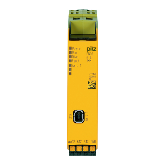
Legend: X4: Connection for proximity switch at axis 1 X12: Mini IO socket for connecting encoder or proximity switch at axis 1. LEDs: – Power – Run – Diag – Fault – Axis 1 Operating Manual PNOZ m EF 1MM 1003108-EN-11... -
Page 10: Safety
Emergency stop equipment Safety circuits in accordance with VDE 0113 Part 1 and EN 60204-1 The product PNOZ m EF 1MM meets the requirements of the standards EN 81-20, EN 81-22 and EN 81-50, harmonised under the Lifts Directive 2014/33/EU, and the require- ments of the standard EN 115-1, harmonised under the Machinery Directive 2006/42/EC. -
Page 11: System Requirements
Are familiar with the basic regulations concerning health and safety / accident prevention, Have read and understood the information provided in this description under "Safety", And have a good knowledge of the generic and specialist standards applicable to the specific application. Operating Manual PNOZ m EF 1MM | 11 1003108-EN-11... -
Page 12: Warranty And Liability
Do not open the housing or make any unauthorised modifications. Please make sure you shut down the supply voltage when performing maintenance work (e.g. exchanging contactors). Operating Manual PNOZ m EF 1MM | 12 1003108-EN-11... -
Page 13: Function Description
Function description Operation The motion monitoring module PNOZ m EF 1MM can monitor one axis. The motion monit- oring module signals the status of the monitored values to the base unit. Depending on the implemented safety circuit, the values may be transferred from the base unit to an output on the control system. - Page 14 : Speed v exceeds the limit value and activates the tolerance range (tolerance time, tol- erance period, tolerance amount) : Tolerance time : Tolerance period Tolerance amount (%): Tolerance amount of limit value in both directions Operating Manual PNOZ m EF 1MM | 14 1003108-EN-11...
-
Page 15: Safe Speed Range Monitoring
Limit value Maximum Speed Limit value Minimum Speed Tolerance amount(%) SSR-M Enable SSR Legend: Enable SSR: – "1": Speed is within the configured range – "0": Speed is outside the configured range Operating Manual PNOZ m EF 1MM | 15 1003108-EN-11... -
Page 16: Safe Direction Monitoring
Depending on the application, serious injury or death may result. Make sure that a tolerance value <24,900,000 increments is configured. From Version 10.0 of the PNOZmulti Configurator, the feasibility of the value will be checked automatically. Operating Manual PNOZ m EF 1MM | 16 1003108-EN-11... -
Page 17: Safe Operating Stop Monitoring
Depending on the application, serious injury or death may result. Make sure that a tolerance value <24,900,000 increments is configured. From Version 10.0 of the PNOZmulti Configurator, the feasibility of the value will be checked automatically. Operating Manual PNOZ m EF 1MM | 17 1003108-EN-11... -
Page 18: Safe Stop 1 Monitoring
Sequence without standstill limit value for automatic STO: Delay Legend Monitoring function SS1-M is activated Delay time elapses, safety function "Safe torque off" (STO) is activated Set delay time for controlled braking of motor Delay Operating Manual PNOZ m EF 1MM | 18 1003108-EN-11... -
Page 19: Safe Stop 2 Monitoring
A maximum of 1 SS2-M element can be configured per axis in the PNOZmulti Configurator. Please note: This monitoring function cannot be used in conjunction with 2 proximity switches because position detection is not possible. Operating Manual PNOZ m EF 1MM | 19 1003108-EN-11... - Page 20 Activation of the monitoring function SS2-M Standstill limit value for automatic SOS reached, monitoring of stop posi- tion (SOS) is activated Delay time elapses Set delay time for controlled braking of motor Delay Operating Manual PNOZ m EF 1MM | 20 1003108-EN-11...
-
Page 21: Safely Limited Acceleration Monitoring (Sla-M)
Monitoring of safely limited acceleration starts, when the trigger threshold is passed, that is, when the start speed changes by the con- figured percentage (V1). When monitoring starts within the maximum trigger time (t1). Operating Manual PNOZ m EF 1MM | 21 1003108-EN-11... -
Page 22: Safely Limited Acceleration Range Monitoring (Sar-M)
Otherwise the functionality is the same as the monitoring function SLA-M. 4 SAR-M elements can be configured per axis in the PNOZmulti Configurator. Operating Manual PNOZ m EF 1MM | 22 1003108-EN-11... -
Page 23: Central Motion Monitoring Functions
If the value of the validation cut-off frequency falls below the configured value, the feasibility check of the sensors will no longer be run. Operating Manual PNOZ m EF 1MM | 23 1003108-EN-11... -
Page 24: System Reaction Time
System reaction time Calculation of the maximum reaction time between an input switching off and a linked out- put in the system switching off is described in the document "PNOZmulti System Expan- sion". Operating Manual PNOZ m EF 1MM | 24 1003108-EN-11... -
Page 25: Proximity Switch
NPN / NPN De-energised Ini 1 energised De-energised Ini 2 energised > 1% of period length NPN / PNP De-energised Ini 1 energised energised Ini 2 De-energised > 1% of period length Operating Manual PNOZ m EF 1MM | 25 1003108-EN-11... -
Page 26: Encoder
The encoders can be connected with or without Z index (0 index). The cables used to connect the encoders must be shielded (see connection diagrams in the chapter entitled "EMC-compliant wiring"). Operating Manual PNOZ m EF 1MM | 26 1003108-EN-11... - Page 27 The maximum frequency of the used encoders must be entered for a complete configura- tion. Pay attention to the values in the technical details. Operating Manual PNOZ m EF 1MM | 27 1003108-EN-11...
-
Page 28: Output Signals
Output signals Sin/Cos (1 Vss) Single ended with reference track (e.g. Hiperface ®) REFSIN +0,5 V REFSIN -0,5 V 2,5 V REFSIN REFCOS +0,5 V REFCOS -0,5 V REFCOS 2,5 V Operating Manual PNOZ m EF 1MM | 28 1003108-EN-11... -
Page 29: Adapters For Encoders
The adapter records the data between the encoder and the drive and makes it available to the PNOZ m EF 1MM via the Mini-IO socket. Pilz supplies complete adapters as well as ready-made cable with Mini-IO connector, which can be used when making your own adapter. The range of products in this area is con- stantly being expanded. -
Page 30: Installation
Electrostatic discharge can damage components. Ensure against discharge before touching the product, e.g. by touching an earthed, conductive sur- face or by wearing an earthed armband. Dimensions in mm 22,5 101,4 (4,11“) (0,88“) Operating Manual PNOZ m EF 1MM | 30 1003108-EN-11... -
Page 31: Connect The Base Unit And Expansion Modules
Please refer to the document "PNOZmulti System Expansion" for details of the number of modules that can be connected to the base unit and the module types. Operating Manual PNOZ m EF 1MM | 31 1003108-EN-11... -
Page 32: Commissioning
If possible, the connections for the various earth potentials (GND, A2 ) should not be con- nected on the PNOZ m EF 1MM but should be connected directly to the GNDs on the connected units. otherwise noise susceptibility may be increased significantly (conductor loops are not permitted). -
Page 33: Connection Of Proximity Switches
– The safety level is reduced. – The cables for connecting the proximity switches must be laid separately. – The supply voltage of the proximity switches must be monitored (e.g. via track S). Operating Manual PNOZ m EF 1MM | 33 1003108-EN-11... -
Page 34: Connection Of An Encoder
– Output frequency – Supply voltage – Operating temperature – Existing interference When calculating the maximum cable length, remember that the length of the adapter cable must also be taken into account. Operating Manual PNOZ m EF 1MM | 34 1003108-EN-11... - Page 35 Use an adapter cable that’s less than 5 m in length. Lay the adapter cable separately from any potential sources of interference, such as drive cables leading to the motor, for ex- ample. Operating Manual PNOZ m EF 1MM | 35 1003108-EN-11...
-
Page 36: Connect Encoder
Connect encoder with Z index Encoder types: TTL single ended Z Index HTL single ended Z Index Please note: Tracks /A, /B and /Z must remain free PNOZ m EF 1MM Encoder Mini-IO Operating Manual PNOZ m EF 1MM | 36 1003108-EN-11... -
Page 37: Connect Encoder Via An Adapter
Connect encoder via an adapter The adapter (see Accessories [ 61]) is connected between the encoder and the drive. The output on the adapter is connected to the Mini-IO socket on the PNOZ m EF 1MM. Encoder Mini-IO PNOZ m EF 1MM... - Page 38 – Hiperface (A,/A,B,/B) + Ini pnp (Z) – Hiperface (A,/A,B,/B) + HTL differential (A as Z) – Hiperface (A,/A,B,/B) + HTL single ended (A as Z) Please note: Track /Z must remain free!! Operating Manual PNOZ m EF 1MM | 38 1003108-EN-11...
-
Page 39: Emc-Compliant Wiring
EMC-compliant wiring for connecting an encoder L1 N L1 N Cabinet Power Power Supply Supply PNOZmulti 2 Encoder Base Module Motion Monitoring Shielded Connection Box PNOZmulti 2 Module Adapter cable DIN-Rail Encoder Operating Manual PNOZ m EF 1MM | 39 1003108-EN-11... - Page 40 To avoid EMC interference we recommend that the shield on the sensor cable is connected to earth at C or E. However, depending on the application, it may be helpful to establish the connection to functional earth at another point (in this case A). Operating Manual PNOZ m EF 1MM | 40 1003108-EN-11...
- Page 41 (in this case A or B). Conductor loops outside the shield must be avoided. If a shielded junction box is not used, the shield must run continuously from the sensor to the evaluation device. Operating Manual PNOZ m EF 1MM | 41 1003108-EN-11...
- Page 42 (in this case A or B). Conductor loops outside the shield must be avoided. If a shielded junction box is not used, the shield must run continuously from the sensor to the evaluation device. Operating Manual PNOZ m EF 1MM | 42 1003108-EN-11...
-
Page 43: Download Modified Project To The Pnozmulti System
Proceed as described in the operating manual for the base unit. NOTICE For the commissioning and after every user program change, you must check whether the safety devices are functioning correctly. Operating Manual PNOZ m EF 1MM | 43 1003108-EN-11... -
Page 44: Operation
Power Diag Fault Axis 1 No supply voltage Expansion module PNOZ m EF 1MM is in a STOP con- dition. Expansion module PNOZ m EF 1MM is running without error, no axis is active. Axis is not yet ready. Axis is configured and is running. -
Page 45: Technical Details
Input's frequency range 0 - 500 kHz Configurable monitoring frequency Without hysteresis 0,1 Hz - 500 kHz Inputs Potential isolation Times Reaction time after limit value is exceeded 1/f_ist + 16 ms Operating Manual PNOZ m EF 1MM | 45 1003108-EN-11... - Page 46 Mechanical data Mounting position horizontally on mounting rail DIN rail Top hat rail 35 x 7,5 EN 50022 Recess width 27 mm Material Bottom Front Connection type Spring-loaded terminal, screw terminal Operating Manual PNOZ m EF 1MM | 46 1003108-EN-11...
-
Page 47: Safety Characteristic Data
A safety function's SIL/PL values are not identical to the SIL/PL values of the units that are used and may be different. We recommend that you use the PAScal software tool to calculate the safety function's SIL/PL values. Operating Manual PNOZ m EF 1MM | 47 1003108-EN-11... -
Page 48: Supplementary Data
PNOZ m EF 1MM. INFORMATION The safety-related characteristic data of the PNOZ m EF 1MM and all other devices that are used must be taken into account when calculating the safety level. We recommend that you use the PAScal software tool to calcu- late the safety function's SIL/PL values. -
Page 49: Safety Functions
Safely limited acceleration monitoring (SLA-M) Safely limited acceleration range monitoring (SAR-M) The safety functions of the PNOZ m EF 1MM are monitoring functions, whereby a safe out- put signal is used to show if defined limit values are exceeded. The reaction function that takes place (e.g. shutting down the drive, activating a mechanical... -
Page 50: Safety-Related Characteristic Data For Operation With Non-Safety-Related Encoder Without Addi
Sin/Cos output signals 1Vss, reference voltage Sin/Cos output signals 1Vss, differential 9.1.3.2 Safety-related architecture To calculate the safety function you will need the following data for the "sensor" subsystem and the subsystem PNOZ m EF 1MM: Sensor Subsystem PNOZ m EF 1MM Category MTTFd... -
Page 51: Safety-Related Characteristic Data For Operation With Non-Safety-Related Encoder With Mech
Sensor Actuator non-safe encoder Logic Diagnostic To calculate the safety function you will need the following data for the "sensor" subsystem and the subsystem "PNOZ m EF 1MM": Sensor Subsystem PNOZ m EF 1MM Category MTTFd Operating mode PFH (1/h) -
Page 52: Achievable Safety Level
If a maximum error variable is exceeded (set/true comparison) the drive controller must switch to a fault condition and stop the drive (drag error detection). The error reaction to drag error detection should be a controlled motor stop. Operating Manual PNOZ m EF 1MM | 52 1003108-EN-11... -
Page 53: Safety-Related Architecture
Logic Diagnostic Drive Control Diagnostic To calculate the safety function you will need the following data for the "sensor" subsystem and the subsystem "PNOZ m EF 1MM": Sensor Subsystem PNOZ m EF 1MM Category MTTFd Operating mode PFH (1/h) -
Page 54: Safety-Related Characteristic Data For Operation With A Safe Encoder
Sensor Actuator safe encoder Logic Diagnostic To calculate the safety function you will need the following data for the "sensor" subsystem and the subsystem "PNOZ m EF 1MM": Sensor Subsystem PNOZ m EF 1MM PFH (1/h) Operating mode PFH (1/h) -
Page 55: Achievable Safety Level
Diagnostic Sin/Cos output signals 1Vss, differential with Z index 9.1.7.2 Safety-related architecture SRP/CS SRP/CS SRP/CS Logic Sensor Logic PNOZ m EF 1MM Sensor Actuator safe encoder with track Z Logic Diagnostic Operating Manual PNOZ m EF 1MM | 55 1003108-EN-11... -
Page 56: Achievable Safety Level
Supplementary data To calculate the safety function you will need the following data for the "sensor" subsystem and the subsystem "PNOZ m EF 1MM": Sensor Subsystem PNOZ m EF 1MM PFH (1/h) Operating mode PFH (1/h) See manufacturer Monitoring 1,35E-09 2 sensors 9.1.7.3... -
Page 57: Safety-Related Architecture
Logic Diagnostic Sensor proximity switch To calculate the safety function you will need the following data for the "sensor" subsystem and the subsystem PNOZ m EF 1MM: Sensor Subsystem PNOZ m EF 1MM Category MTTFd Operating mode PFH (1/h) -
Page 58: Safety-Related Characteristic Data For Operation With 2 Proximity Switches
Permitted sensor types: Inductive proximity switches Permitted output circuits: 9.1.9.2 Safety-related architecture SRP/CS SRP/CS SRP/CS Sensor Logic Logic PNOZ m EF 1MM Sensor Actuator proximity switch Logic Diagnostic Sensor proximity switch Operating Manual PNOZ m EF 1MM | 58 1003108-EN-11... -
Page 59: Achievable Safety Level
Supplementary data To calculate the safety function you will need the following data for the "sensor" subsystem and the subsystem "PNOZ m EF 1MM": Sensor Subsystem PNOZ m EF 1MM Category MTTFd Operating mode PFH (1/h) Manufacturer- 90 % Monitoring... -
Page 60: Safety-Related Architecture
The supply voltage of the proximity switches must be monitored as a measure against sys- temic failure. To calculate the safety function you will need the following data for the "sensor" subsystem and the subsystem "PNOZ m EF 1MM": Sensor Subsystem PNOZ m EF 1MM... -
Page 61: Order Reference
MM A MINI-IO CAB99 1.50 m 772 200 MM A MINI-IO CAB99 2.50 m 772 201 MM A MINI-IO CAB99 5.0 m 772 202 Product type Features Order no. PNOZ msi b4 Box Connection box 773 845 Operating Manual PNOZ m EF 1MM | 61 1003108-EN-11... - Page 62 We are represented internationally. Please refer to our homepage www.pilz.com for further details or contact our headquarters. Headquarters: Pilz GmbH & Co. KG, Felix-Wankel-Straße 2, 73760 Ostfildern, Germany Telephone: +49 711 3409-0, Telefax: +49 711 3409-133, E-Mail: info@pilz.com, Internet: www.pilz.com...
Need help?
Do you have a question about the PNOZ m EF 1MM and is the answer not in the manual?
Questions and answers