
Related Manuals for Pilz PNOZ m EF 1MM


Summary of Contents for Pilz PNOZ m EF 1MM
- Page 1 PNOZ m EF 1MM Configurable control systems PNOZmulti 2 Operating Manual1003108EN06...
- Page 2 Preface This document is a translation of the original document. All rights to this documentation are reserved by Pilz GmbH & Co. KG. Copies may be made for internal purposes. Suggestions and comments for improving this documentation will be gratefully received. Pilz®, PIT®, PMI®, PNOZ®, Primo®, PSEN®, PSS®, PVIS®, SafetyBUS p®, SafetyEYE®, SafetyNET p®, the spirit of safety® are registered and protected trademarks of Pilz GmbH & Co. KG in some countries. SD means Secure Digital...
-
Page 3: Table Of Contents
Content Section 1 Introduction Validity of documentation Using the documentation Definition of symbols Section 2 Overview Scope of supply Unit features Front view Section 3 Safety Intended use System requirements Safety regulations 3.3.1 Safety assessment 3.3.2 Use of qualified personnel 3.3.3 Warranty and liability 3.3.4 Disposal 3.3.5 For your safety Section 4 Function description Operation Block diagram Monitoring functions System reaction time Proximity switches Encoder 4.6.1 Output signals 4.6.2 Adapters for encoders Section 5 Installation General installation guidelines Dimensions in mm Connect the base unit and expansion modules... - Page 4 Content Section 7 Operation Messages Section 8 Technical details Safety characteristic data Section 9 Supplementary data Categories 9.1.1 Safety level 9.1.2 Safety functions 9.1.3 Safetyrelated characteristic data for operation with nonsafetyrelated en coder without additional requirements 9.1.3.1 Permitted sensor types and output signals 9.1.3.2 Safetyrelated architecture 9.1.3.3 Achievable safety level 9.1.4 Safetyrelated characteristic data for operation with nonsafetyrelated en coder with mechanical fault exclusion 9.1.4.1 Permitted sensor types and output signals 9.1.4.2 Safetyrelated architecture 9.1.4.3 Achievable safety level 9.1.5 Safetyrelated characteristic data for operation with nonsafetyrelated en coder with diagnostics via the drive controller 9.1.5.1 Permitted sensor types and output signals 9.1.5.2 Requirements of the drive controller 9.1.5.3 Safetyrelated architecture 9.1.5.4 Achievable safety level...
-
Page 5: Operating Manual Pnoz M Ef 1Mm
Introduction Introduction Validity of documentation This documentation is valid for the product PNOZ m EF 1MM. It is valid until new docu mentation is published. This operating manual explains the function and operation, describes the installation and provides guidelines on how to connect the product. Using the documentation This document is intended for instruction. Only install and commission the product if you have read and understood this document. The document should be retained for future ref erence. Definition of symbols Information that is particularly important is identified as follows: DANGER! This warning must be heeded! It warns of a hazardous situation that poses an immediate threat of serious injury and death and indicates preventive measures that can be taken. WARNING! This warning must be heeded! It warns of a hazardous situation that could lead to serious injury and death and indicates preventive measures that can be taken. CAUTION! This refers to a hazard that can lead to a less serious or minor injury plus material damage, and also provides information on preventive measures that can be taken. NOTICE This describes a situation in which the product or devices could be dam aged and also provides information on preventive measures that can be taken. It also highlights areas within the text that are of particular import ance. Operating Manual PNOZ m EF 1MM 1003108EN06... - Page 6 Introduction INFORMATION This gives advice on applications and provides information on special fea tures. Operating Manual PNOZ m EF 1MM 1003108EN06...
-
Page 7: Overview
Overview Overview Scope of supply Unit features Using the product PNOZ m EF 1MM: Expansion module for connection to a base unit from the configurable control system PNOZmulti 2 . The product has the following features: Can be configured in the PNOZmulti Configurator Monitoring of 1 axis Measured value recorded by proximity switch and encoder Monitoring functions – Safe speed monitoring (SSM) – Safe speed range monitoring (SSRM) – Safe direction of movement monitoring (SDIM) – Safe operating stop monitoring (SOSM) – Analogue voltage (track S) LED display for: – Supply voltage – Diagnostics – Axis status – Error Please refer to the document "PNOZmulti System Expansion" for the PNOZmulti base units that can be connected. Operating Manual PNOZ m EF 1MM 1003108EN06... -
Page 8: Front View
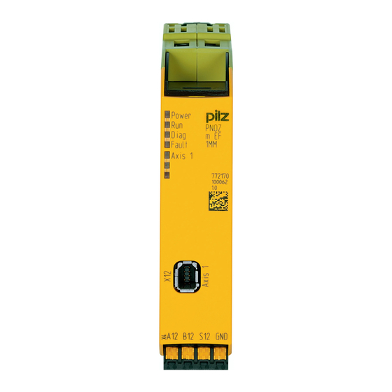
Overview Front view Legend: X4: Connection for proximity switch at axis 1 X12: Mini IO socket for connecting encoder or proximity switch at axis 1. LEDs: – Power – – Diag – Fault – Axis 1 Operating Manual PNOZ m EF 1MM 1003108EN06... -
Page 9: Safety
Safety Safety Intended use The motion monitoring expansion module monitors safety functions in accordance with EN 6180052 for safe motion monitoring. The following monitoring functions are performed: Safe direction of movement monitoring (SDIM) Safe operating stop monitoring (SOSM) Safe speed range monitoring (SSRM) Safe speed monitoring (SSM) The expansion module meets the requirements of EN IEC 61508 up to SIL 3 and EN ISO 138491 up to PL e. The expansion module may only be connected to a base unit from the configurable system PNOZmulti 2 (please refer to the document "PNOZmulti System Expansion" for details of the base units that can be connected). The configurable system PNOZmulti 2 is used for the safetyrelated interruption of safety circuits and is designed for use in: Emergency stop equipment Safety circuits in accordance with VDE 0113 Part 1 and EN 602041 The following is deemed improper use in particular: Any component, technical or electrical modification to the product Use of the product outside the areas described in this manual Use of the product outside the technical details (see Technical details [ 34]). NOTICE EMCcompliant electrical installation The product is designed for use in an industrial environment. The product may cause interference if installed in other environments. If installed in other environments, measures should be taken to comply with the applicable standards and directives for the respective installation site with regard to in terference. System requirements Please refer to the "Product Modifications PNOZmulti" document in the "Version overview" section for details of which versions of the base unit and PNOZmulti Configurator can be used for this product. Operating Manual PNOZ m EF 1MM 1003108EN06... -
Page 10: Safety Regulations
Safety Safety regulations 3.3.1 Safety assessment Before using a unit it is necessary to perform a safety assessment in accordance with the Machinery Directive. Functional safety is guaranteed for the product as a single component. However, this does not guarantee the functional safety of the overall plant/machine. In order to achieve the re quired safety level for the overall plant/machine, define the safety requirements for the plant/machine and then define how these must be implemented from a technical and organ isational standpoint. 3.3.2 Use of qualified personnel The products may only be assembled, installed, programmed, commissioned, operated, maintained and decommissioned by competent persons. A competent person is someone who, because of their training, experience and current pro fessional activity, has the specialist knowledge required to test, assess and operate the work equipment, devices, systems, plant and machinery in accordance with the general standards and guidelines for safety technology. It is the company’s responsibility only to employ personnel who: Are familiar with the basic regulations concerning health and safety / accident preven tion Have read and understood the information provided in this description under "Safety" And have a good knowledge of the generic and specialist standards applicable to the specific application. 3.3.3 Warranty and liability All claims to warranty and liability will be rendered invalid if The product was used contrary to the purpose for which it is intended Damage can be attributed to not having followed the guidelines in the manual Operating personnel are not suitably qualified Any type of modification has been made (e.g. exchanging components on the PCB boards, soldering work etc.). 3.3.4 Disposal In safetyrelated applications, please comply with the mission time T in the safetyre lated characteristic data. When decommissioning, please comply with local regulations regarding the disposal of electronic devices (e.g. Electrical and Electronic Equipment Act). Operating Manual PNOZ m EF 1MM 1003108EN06... -
Page 11: For Your Safety
Safety 3.3.5 For your safety The unit meets all the necessary conditions for safe operation. However, you should always ensure that the following safety requirements are met: This operating manual only describes the basic functions of the unit. The expanded functions are described in the PNOZmulti Configurator's online help. Only use these functions once you have read and understood the documentations. Do not open the housing or make any unauthorised modifications. Please make sure you shut down the supply voltage when performing maintenance work (e.g. exchanging contactors). Operating Manual PNOZ m EF 1MM 1003108EN06... -
Page 12: Function Description
Function description Function description Operation The motion monitoring module PNOZ m EF 1MM can monitor one axis. The motion monit oring module signals the status of the monitored values to the base unit. Depending on the implemented safety circuit, the values may be transferred from the base unit to an output on the control system. Proximity switches or encoders are used to record the values. The configuration of the motion monitoring module is described in detail in the PNOZmulti Configurator's online help. The relay conforms to the following safety criteria: The circuit is redundant with builtin selfmonitoring. The safety function remains effective in the case of a component failure. Block diagram A12 B12 S12 GND Mini-IO Monitoring functions Safe speed monitoring The "Safe speed monitoring" function (SSM) monitors whether the current speed exceeds a limit value. If the configured limit value is exceeded, the output switches off. As soon as the value falls below the limit value (plus hysteresis), the output switches off again. 8 limit values can be configured per axis in the PNOZmulti Configurator. A tolerance range may also be set for the limit values used to monitor the speed. This toler ance range modifies the set limit values. As a result, oneoff or periodic overshoots that ex ceed the limit values can be tolerated. The following values can be configured for the tolerance range: Operating Manual PNOZ m EF 1MM 1003108EN06... - Page 13 Function description Tolerance time (t1), which takes into account the length of the overshoots (maximum time for which the limit value may be exceeded). It must not be possible that the sum of all the overshoots exceeds the tolerance time (t1) within a tolerance period (t2). Tolerance period (t2), which takes into account the oscillation period (minimum time that must elapse between one limit value overshoot and the next) Tolerance amount (%), which takes into account the amplitude of the overshoots (max imum permitted percentage by which the configured limit values may be exceeded) Tolerance amount (%) Limit value Speed + Limit value Speed - Tolerance amount (%) Legend: : Activation of the safety function SSM : Speed v exceeds the limit value and activates the tolerance range (tolerance time, tolerance period, tolerance amount) : Tolerance time : Tolerance period Tolerance amount (%): Tolerance amount of limit value in both directions Safe speed range monitoring The "Safe speed range monitoring" function (SSRM) monitors the current speed to ensure it stays within a maximum and minimum permitted limit value. If the speed is outside the configured range, the output switches off. As soon as the speed returns to within the configured range (plus hysteresis), the output switches back on. A tolerance range may also be set for the limit values used to monitor the speed range. This tolerance range modifies the set limit values. As a result, oneoff or periodic over shoots that exceed the range limits can be tolerated. The following values can be configured for the tolerance range: Tolerance time (t1), which takes into account the length of the overshoots (maximum time for which the limit value may be exceeded). It must not be possible that the sum of all the overshoots exceeds the tolerance time (t1) within a tolerance period (t2).
- Page 14 Function description Tolerance period (t2), which takes into account the oscillation period (minimum time that must elapse between one limit value overshoot and the next) Tolerance amount as a %, which takes into account the amplitude of the overshoots (maximum permitted percentage by which the limit value may be exceeded) SSR-M Tolerance amount (%) Limit value Maximum speed Limit value Minimum speed Tolerance amount (%) SSR-M Legend: : Activation of the safety function SSRM : Speed v exceeds the limit value and activates the tolerance range (tolerance time, tolerance period, tolerance amount) : Tolerance time : Tolerance period Tolerance amount (%): Tolerance amount of the two limit values, maximum and min imum speed Safe direction of movement monitoring The "Safe Direction Monitor" (SDIM) monitors the defined direction of movement of the drive axis (positive or negative). Safe direction of movement monitoring is activated via the start input. It remains active until the position tolerance is exceeded. As long as the current position is within the tolerated position, you can display the tolerance field at any time by re activating the start input (retrigger). As a result, the current position can be used at any time as the start point for the monitoring function. Operating Manual PNOZ m EF 1MM 1003108EN06...
- Page 15 Function description WARNING! Potential loss of safety function with a tolerance value >24,900,000 incre ments! The following applies when using a PNOZmulti Configurator Version <10.0: If a tolerance value >24,900,000 increments is configured in the PNOZmulti Configurator, the monitoring function will no longer be evaluated correctly. Depending on the application, serious injury or death may result. Make sure that a tolerance value <24,900,000 increments is configured. From Version 10.0 of the PNOZmulti Configurator, the feasibility of the value will be checked automatically. The monitoring function SDIM is not available in proximity switches where no position can be determined. Safe operating stop monitoring The "Safe Operation Stop Monitor" (SOSM) monitors whether the standstill position re mains within a configured tolerance window. Safe operating stop monitoring is activated via the start input. It remains active until the direction tolerance is exceeded. As long as the current position is within the tolerated position, you can display the tolerance field at any time by reactivating the start input (retrigger). As a result, the current position can be used at any time as the start point for the monitoring function. Operating Manual PNOZ m EF 1MM 1003108EN06...
-
Page 16: System Reaction Time
Function description WARNING! Potential loss of safety function with a tolerance value >24,900,000 incre ments! The following applies when using a PNOZmulti Configurator Version <10.0: If a tolerance value >24,900,000 increments is configured in the PNOZmulti Configurator, the monitoring function will no longer be evaluated correctly. Depending on the application, serious injury or death may result. Make sure that a tolerance value <24,900,000 increments is configured. From Version 10.0 of the PNOZmulti Configurator, the feasibility of the value will be checked automatically. Hysteresis A hysteresis can be configured for the monitoring functions. This prevents the outputs from bouncing if there are fluctuations around the response value. The hysteresis takes effect when the output is switched on. Validation cutoff frequency As implausible signals may arise due to edge jitter on the sensors around the standstill pos ition, a validation cutoff frequency must be configured for sensor types with proximity switches in the PNOZmulti Configurator (edge jitter is caused by the position control of the drive frequency converter or by external interference signals). If the value of the validation cutoff frequency falls below the configured value, the feasibility check of the sensors will no longer be run. System reaction time Calculation of the maximum reaction time between an input switching off and a linked out put in the system switching off is described in the document "PNOZmulti System Expan sion". Operating Manual PNOZ m EF 1MM 1003108EN06... -
Page 17: Proximity Switches
Function description Proximity switches The following proximity switches can be used with a pnp or npn output: – Inductive – Capacitive The proximity switches must be fitted so that at least one is always activated. In other words, the proximity switches must be fitted so that the recorded signals always over lap. The cable used to connect the proximity switches must be shielded (see connection diagrams in the chapter entitled "EMCcompliant wiring"). A DC voltage in the range of 0 30 V can be monitored via track S. It should be used to monitor the supply voltage of the proximity switches. CAUTION! Please note: Connection of the proximity switches may only be performed in threewire technology and not in twowire technology. Proximity switch assembly: Ini 1 Ini 2 Signal characteristics: Proximity switch combinations Signal image in an energised state PNP / PNP Energised Ini 1 Deenergised Energised Ini 2 Deenergised > 1% of period length Deenergised NPN / NPN Ini 1 Energised Deenergised Ini 2 Energised > 1% of period length Operating Manual PNOZ m EF 1MM... -
Page 18: Encoder
Function description Proximity switch combinations Signal image in an energised state NPN / PNP Deenergised Ini 1 Energised Energised Ini 2 Deenergised > 1% of period length PNP / NPN Energised Ini 1 Deenergised Deenergised Energised Ini 2 > 1% of period length CAUTION! Appropriate installation measures should be taken to prevent a foreign body coming between the signal encoder and the proximity switch. If not, the for eign body could cause invalid signals. Please note the values stated in the sensor's technical details. For a full configuration, the maximum frequency of the sensors you are using must be entered in the PNOZmulti Configurator (see sensor's data sheet). Encoder The following encoders can be used: – TTL, HTL (singleended or differential signals) – Sin/Cos 1 Vss – Hiperface® The encoders can be connected with or without Z index (0 index). The cables used to connect the encoders must be shielded (see connection diagrams in the chapter entitled "EMCcompliant wiring"). A pnp proximity switch can also be connected to track Z for monitoring broken shear pins. Please note: Monitoring for broken shearpins does not become active until –... -
Page 19: Output Signals
Function description – The tolerance for detecting feasibility errors has elapsed. The minimum speed and tolerance depend on the ratio of the frequency at tracks AB "f " to the frequency at track Z "f " in your configuration (see PNOZmulti Configurator Element Motion Monitor, value Calculated Ratio AB/Z). Minimum speed: – Calculated ratio AB/Z ≥ 1.0 = 10 mHz or f = (f ) x 10 mHz – when f Verh. < 1.0 = 10 mHz or f = 10 mHz/(f Tolerance for detecting feasibility errors: – when fAB/fZ Verh. ≥ 1.0 7.5 Zpulses or 7.5 x (f ) ABpulses – when fAB/fZ Verh. < 1.0 4.5 ABpulses or 4.5/(f ) Zpulses With Hiperface encoders, the Sin Cos track is recorded and monitored via an adapter (see Adapters for encoders [ 21]). Track S can be used: – To connect an encoder's error output. – To monitor voltages between 0 V and 30 V for a permitted upper and lower limit. For example, the encoder's supply voltage can be monitored. The maximum frequency of the used encoders must be entered for a complete config uration. Pay attention to the values in the technical details. 4.6.1 Output signals Output signals TTL, HTL... - Page 20 Function description Differential (/Z) Output signals Sin/Cos (1 Vss) Single ended with reference track (e.g. Hiperface ®) REFSIN +0,5 V REFSIN -0,5 V 2,5 V REFSIN REFCOS +0,5 V REFCOS -0,5 V REFCOS 2,5 V Operating Manual PNOZ m EF 1MM 1003108EN06...
-
Page 21: Adapters For Encoders
Function description Differential with/without Z index (e.g. Heidenhain 1 Vss) 4.6.2 Adapters for encoders The adapter records the data between the encoder and the drive and makes it available to the PNOZ m EF 1MM via the MiniIO socket. Pilz supplies complete adapters as well as readymade cable with MiniIO connector, which can be used when making your own adapter. The range of products in this area is con stantly being expanded. Please contact us about the range of adapters that is currently available. Operating Manual PNOZ m EF 1MM 1003108EN06... -
Page 22: Installation
Installation Installation General installation guidelines The unit should be installed in a control cabinet with a protection type of at least IP54. Fit the safety system to a horizontal mounting rail. The venting slots must face upward and downward. Other mounting positions could damage the safety system. Use the locking elements on the rear of the unit to attach it to a mounting rail. In environments exposed to heavy vibration, the unit should be secured using a fixing element (e.g. retaining bracket or end angle). Open the locking slide before lifting the unit from the mounting rail. To comply with EMC requirements, the mounting rail must have a low impedance con nection to the control cabinet housing. The ambient temperature of the PNOZmulti units in the control cabinet must not exceed the figure stated in the technical details, otherwise air conditioning will be required. NOTICE Damage due to electrostatic discharge! Electrostatic discharge can damage components. Ensure against discharge before touching the product, e.g. by touching an earthed, conductive sur face or by wearing an earthed armband. Dimensions in mm 22,5 101,4 (4,11“) (0,88“) Connect the base unit and expansion modules Connect the base unit and the expansion module as described in the operating instructions for the base units. Connect the black/yellow terminator to the expansion module. Install the expansion module in the position in which it is configured in the PNOZmulti Configurator. Operating Manual PNOZ m EF 1MM 1003108EN06... - Page 23 Installation The position of the expansion modules is defined in the PNOZmulti Configurator. The ex pansion modules are connected to the left or right of the base unit, depending on the type. Please refer to the document "PNOZmulti System Expansion" for details of the number of modules that can be connected to the base unit and the module types. Operating Manual PNOZ m EF 1MM 1003108EN06...
-
Page 24: Commissioning
Commissioning Commissioning Wiring The wiring is defined in the circuit diagram of the PNOZmulti Configurator. Please note: Information given in the "Technical details [ 34]" must be followed. Use copper wiring with a temperature stability of 75°C. The cable used to connect the encoders and proximity switches must be shielded (see connection diagrams in the chapter entitled "EMCcompliant wiring"). The shield may only be connected to earth at a single point. Earth loops should be avoided. If possible, the connections for the various earth potentials (GND, A2 ) should not be connected on the PNOZ m EF 1MM but should be connected directly to the GNDs on the connected units, otherwise noise susceptibility may be increased significantly (con ductor loops are not permitted). CAUTION! Only connect and disconnect the expansion module when the supply voltage is switched off. Pin assignment of MiniIO socket MiniIO socket 8pin Track Operating Manual PNOZ m EF 1MM 1003108EN06... -
Page 25: Connection Of Proximity Switches
Commissioning Connection of proximity switches The following proximity switch combinations can be connected: A: pnp, B: pnp A: npn, B: npn A: pnp, B: npn A: npn, B: pnp When connecting proximity switches please note: Proximity switches are connected to terminals A12, B12, GND or tracks A, B and GND of the MiniIO socket. Track S (S12) should be used to monitor the supply voltage (see drawing). A permitted voltage range can be entered in the menu. Connect the proximity switch to 24 VDC of the power supply. When connecting the proximity switches, please refer to the chapter entitled "EMC compliant wiring". Invalid signals may occur with cable lengths >50 m. In this case we recommend that you connect a resistor between the signal lines, as shown in the diagrams. Connection of the proximity switches may only be performed in threewire technology and not in twowire technology. MiniIO pnp proximity switch with resistor R = 10 kOhm MiniIO Operating Manual PNOZ m EF 1MM 1003108EN06... -
Page 26: Connection Of An Encoder
Commissioning npn proximity switch with resistor R = 47 kOhm MiniIO Connection of an encoder Proceed as follows when connecting the encoder: The encoder can be connected via an adapter (e.g. MM A MiniIOCAB01) or directly to the PNOZ m EF 1MM. Use only shielded cables for all connections. Please refer to the chapter entitled "EMC compliant wiring". Always connect GND on the encoder to GND on the MiniIO connector. 6.4.1 Connect encoder Encoder types: TTL single ended HTL single ended Please note: Tracks/A, /B, Z, and /Z must remain free Encoder PNOZ m EF 1MM MiniIO Encoder types: TTL differential HTL differential sin/cos 1 Vss Hiperface Operating Manual PNOZ m EF 1MM 1003108EN06... -
Page 27: Connect Encoder With Z Index
Commissioning Please note: Tracks/A, /B, Z, and /Z must remain free Encoder PNOZ m EF 1MM MiniIO 6.4.2 Connect encoder with Z index Encoder types: TTL single Z Index HTL single Z Index Please note: Tracks /A, /B and /Z must remain free Encoder MiniIO PNOZ m EF 1MM Encoder types: TTL diff. Z Index HTL diff. Z Index sin/cos 1 Vss Z Index Encoder PNOZ m EF 1MM MiniIO Operating Manual PNOZ m EF 1MM 1003108EN06... -
Page 28: Connect Encoder Via An Adapter
Commissioning 6.4.3 Connect encoder via an adapter The adapter (e.g. MM A MiniIOCAB01) is connected between the encoder and the drive. The output on the adapter is connected to the MiniIO socket on the PNOZ m EF 1MM. Encoder MiniIO PNOZ m EF 1MM Connection of proximity switch and encoder When connecting the encoders and proximity switches, please refer to the chapter entitled "EMCcompliant wiring". Sensor types: Configuration: HTL single Z Freq. Ini pnp – HTL single ended (A,B) + Ini pnp (Z) – HTL single ended (A,B) + HTL differential (A as Z) – HTL single ended (A,B) + HTL single ended (A as Z) Configuration: TTL single Z Freq. Ini pnp – TTL single ended (A,B) + Ini pnp (Z) – TTL single ended (A,B) + HTL differential (A as Z) – TTL single ended (A,B) + HTL single ended (A as Z) Please note: Tracks /A, /B and /Z must remain free. Encoder PNOZ m EF 1MM MiniIO Operating Manual PNOZ m EF 1MM 1003108EN06... - Page 29 Commissioning Sensor types: Configuration: TTL differential Z Freq. Ini pnp – TTL differential (A,/A,B,/B) + Ini pnp (Z) – TTL differential (A,/A,B,/B) + HTL differential (A as Z) – TTL differential (A,/A,B,/B) + HTL single ended (A as Z) Configuration: HTL differential Z Freq. Ini pnp – HTL differential (A,/A,B,/B) + Ini pnp (Z) – HTL differential (A,/A,B,/B) + HTL differential (A as Z) – HTL differential (A,/A,B,/B) + HTL single ended (A as Z) Configuration: sin/cos 1 Vss Z Freq. Ini pnp – sin/cos 1 Vss (A,/A,B,/B) + Ini pnp (Z) – sin/cos 1 Vss (A,/A,B,/B) + HTL differential (A as Z) – sin/cos 1 Vss (A,/A,B,/B) + HTL single ended (A as Z) Configuration: Hiperface Z Freq. Ini pnp – Hiperface (A,/A,B,/B) + Ini pnp (Z) – Hiperface (A,/A,B,/B) + HTL differential (A as Z) – Hiperface (A,/A,B,/B) + HTL single ended (A as Z) Please note: Track /Z must remain free!! Encoder PNOZ m EF 1MM MiniIO Operating Manual PNOZ m EF 1MM 1003108EN06...
-
Page 30: Emccompliant Wiring
Commissioning EMCcompliant wiring EMCcompliant wiring for connecting an encoder PNOZ m EF 1MM Encoder MiniIO To avoid EMC interference we recommend that the shield on the sensor cables or the housing of the shielded junction box is only connected to earth at a single point: A or B or C or D or E Conductor loops outside the shield must be avoided. If a shielded junction box is not used, the shield must run continuously from the sensor to the evaluation device. Operating Manual PNOZ m EF 1MM 1003108EN06... - Page 31 Commissioning EMCcompliant wiring for connecting an encoder with drive Encoder PNOZ m EF 1MM MiniIO To avoid EMC interference we recommend that the shield on the sensor cables or the housing of the shielded junction box is only connected to earth at a single point: A or B or C or D or E Conductor loops outside the shield must be avoided. If a shielded junction box is not used, the shield must run continuously from the sensor to the evaluation device. Operating Manual PNOZ m EF 1MM 1003108EN06...
-
Page 32: Download Modified Project To The Pnozmulti System
Commissioning EMCcompliant wiring for connecting 2 proximity switches PNOZ m EF 1MM MiniIO To avoid EMC interference we recommend that the shield on the sensor cables or the housing of the shielded junction box is only connected to earth at a single point: A or B or C or D or E Conductor loops outside the shield must be avoided. If a shielded junction box is not used, the shield must run continuously from the sensor to the evaluation device. Download modified project to the PNOZmulti system As soon as an additional expansion module has been connected to the system, the project must be amended using the PNOZmulti Configurator. Proceed as described in the operat ing instructions for the base unit. NOTICE For the commissioning and after every program change, you must check whether the safety devices are functioning correctly. Operating Manual PNOZ m EF 1MM 1003108EN06... -
Page 33: Operation
Operation Operation When the supply voltage is switched on, the PNOZmulti safety system copies the configur ation from the chip card. The LEDs “POWER”, “DIAG”, “FAULT”, “IFAULT” and “OFAULT” will light up on the base unit. Messages Legend: LED on LED flashes LED off Error Power Diag Fault Axis 1 No supply voltage Expansion module PNOZ m EF 1MM running without er ror. Expansion module PNOZ m EF 1MM is in a STOP con dition. Axis is configured and is running. Internal error on the expansion module PNOZ m EF 1MM or on the overall system. Expansion module is in a safe condition. External error on the expansion module PNOZ m EF 1MM or on the overall system. Expansion module is in a safe condition. Internal error on axis 1 of the expansion module PNOZ m EF 1MM. Expansion module is in a safe condition. Implausible sensor signal Implausible sensor signal or internal error Operating Manual PNOZ m EF 1MM 1003108EN06... -
Page 34: Technical Details
Technical details Technical details General Approvals BG, CCC, CE, EAC (Eurasian), TÜV, cULus Listed Application range Failsafe Module's device code 00E3h Electrical data Supply voltage Module supply internal Via base unit Voltage 24,0 V Kind Current consumption 90 mA Power consumption 2,0 W Max. power dissipation of module 2,20 W Status indicator Proximity switch input Number of inputs Input signal level Signal level at "1" 11 30 V Signal level at "0" 0 3 V Input resistance 22 kOhm Input's frequency range 0 5 kHz Configurable monitoring frequency Without hysteresis 0.1 Hz 5 kHz Incremental encoder input Number of inputs Connection type MiniIO female connector, 8pin Input signal level... - Page 35 Technical details Environmental data Storage temperature In accordance with the standard EN 6006821/2 Temperature range 25 70 °C Climatic suitability In accordance with the standard EN 60068230, EN 60068278 Condensation during operation Not permitted EN 611312 Vibration In accordance with the standard EN 6006826 Frequency 5,0 150,0 Hz Acceleration Shock stress In accordance with the standard EN 60068227 Acceleration Duration 11 ms Max. operating height above sea level 2000 m Airgap creepage In accordance with the standard EN 611312 Overvoltage category Pollution degree Rated insulation voltage 30 V Protection type In accordance with the standard EN 60529 Mounting area (e.g. control cabinet) IP54 Housing IP20 Terminals IP20...
-
Page 36: Safety Characteristic Data
Technical details Mechanical data Stripping length with springloaded terminals 9 mm Dimensions Height 101,4 mm Width 22,5 mm Depth 111,0 mm Weight 90 g Where standards are undated, the 201301 latest editions shall apply. Safety characteristic data Operating EN ISO EN ISO EN IEC EN IEC IEC 61511 IEC 61511 EN ISO mode 138491: 138491: 62061 62061 138491: 2008 2008 2008 SIL CL [1/h] Category [year] Monitoring 1 encoder PL d Cat. 2 SIL CL 2 1,80E08 SIL 2... -
Page 37: Supplementary Data
Supplementary data Supplementary data Categories 9.1.1 Safety level The maximum achievable safety level depends, among other things, on the sensor, the wir ing and the operating mode of the PNOZ m EF 1MM. INFORMATION The safetyrelated characteristic data of the PNOZ m EF 1MM and all other devices that are used must be taken into account when calculating the safety level. We recommend that you use the PAScal software tool to calcu late the safety function's SIL/PL values. The safety assessments below only consider the subsystems Sensor and PNOZ m EF 1MM. The Actuator subsystem depends on the application and must also be considered in the overall assessment. Information on the safetyrelated characteristic data for the subsystems Sensor and PNOZ m EF 1MM Example: Sensor subsystem Subsystem PNOZ m EF 1MM Category MTTFd Operating mode PFH [1/h] Manufac 90 % Monitoring 1,83E08 turerspe 1 sensor cific The values for Category and DC can be set for the sensor subsystem, bearing in mind the restrictions stated in the respective chapter. The MTTFd value must be stated by the sensor manufacturer. The values for DC refer to the standard EN 61508. Assuming that all faults are dangerous, MTTF = MTTFd can be set. The characteristic value MTTF is a property of the sensor, which may only be stated by the manufacturer. Forced dynamisation: When monitoring sensors with square output signals (TTL, HTL) or safe sensors, the axis must be moved within 8 hours so that the signal changes on all the connected tracks. -
Page 38: Safety Functions
Supplementary data 9.1.2 Safety functions The following safe monitoring functions are available: Safe speed monitoring (SSM) Safe speed range monitoring (SSRM) Safe direction of movement monitoring (SDIM) Safe operating stop monitoring (SOSM) The safety functions of the PNOZ m EF 1MM are monitoring functions, whereby a safe out put signal is used to show if defined limit values are exceeded. The reaction function that takes place (e.g. shutting down the drive, activating a mechanical brake) when exceeded limit values are detected during the normal operation of the safety function must be defined and implemented by the machine/plant developer and does not form part of the PNOZ m EF 1MM. The monitoring function of the PNOZ m EF 1MM can be used to implement safety functions defined in the standard EN 6180052 for Adjustable speed electrical power drive systems. Safety functions in accordance with Implemented with monitoring function of the EN 6180052 PNOZ m EF 1MM Safe operating stop Safe operating stop monitoring (SOSM) (SOS) Safe speed range (SSR) Safe speed range monitoring (SSRM) Safe direction Safe direction of movement monitoring (SDIM) (SDI) Safe speed monitoring Safe speed monitoring (SSM) (SSM) 9.1.3 Safetyrelated characteristic data for operation with nonsafetyrelated encoder without additional requirements 9.1.3.1 Permitted sensor types and output signals Permitted encoder types: Rotary nonsafetyrelated encoders Linear nonsafetyrelated encoders Permitted output signals: Square output signals TTL, single ended Square output signals TTL, differential... -
Page 39: Safetyrelated Architecture
Supplementary data 9.1.3.2 Safetyrelated architecture To calculate the safety function you will need the following data for the "sensor" subsystem and the subsystem PNOZ m EF 1MM: Sensor Subsystem PNOZ m EF 1MM Category MTTFd Operating mode PFH (1/h) Manufacturer 0 % Monitoring 1,83E08 specific 1 sensor The values for DC refer to the standard EN 61508. *In accordance with EN ISO 138491, Category 1 is only met if the sensor is a "welltried component". 9.1.3.3 Achievable safety level Monitoring PL in accordance with EN SIL CL in accordance with function ISO 138491: 2006 EN IEC 62061 SOSM PL c (Cat. 1) SSRM SDIM 9.1.4 Safetyrelated characteristic data for operation with nonsafetyrelated encoder with mechanical fault exclusion In accordance with EN 6180052: 2007, Table D.16 (Motion and position feedback sensors), fault exclusions are permitted for faults in the mechanical connection between the sensor and motor. 9.1.4.1 Permitted sensor types and output signals Permitted encoder types: Rotary nonsafetyrelated encoders... -
Page 40: Safetyrelated Architecture
Supplementary data 9.1.4.2 Safetyrelated architecture SRP/CS SRP/CS SRP/CS Sensor Logic Logic Sensor PNOZ m EF 1MM Actuator non-safe encoder Logic Diagnostic To calculate the safety function you will need the following data for the "sensor" subsystem and the subsystem PNOZ m EF 1MM: Sensor Subsystem PNOZ m EF 1MM Category MTTFd Operating mode PFH (1/h) Manufacturer 90 % Monitoring 1,83E08 specific 1 sensor The values for DC refer to the standard EN 61508. 9.1.4.3 Achievable safety level Monitoring PL in accordance with EN ISO SIL CL in accordance with function 138491: 2006... -
Page 41: Requirements Of The Drive Controller
If a maximum error variable is exceeded (set/true comparison) the drive controller must switch to a fault condition and stop the drive (drag error detection). The error reaction to drag error detection should be a controlled motor stop. Fault detection via the error variable with subsequent shutdown must meet the require ments of the safety function, with regard to reaction times for example. The drive controller must evaluate the same incremental/SinCos signals from the en coder for control as are processed by the safe evaluation device (important on en coders with combined analogue/digital interface). 9.1.5.3 Safetyrelated architecture SRP/CS SRP/CS SRP/CS Logic Sensor Logic Sensor PNOZ m EF 1MM Actuator non-safe encoder Logic Diagnostic Drive Control Diagnostic To calculate the safety function you will need the following data for the "sensor" subsystem and the subsystem PNOZ m EF 1MM: Sensor Subsystem PNOZ m EF 1MM Category MTTFd Operating mode PFH (1/h) Manufacturer 90 % Monitoring 1,83E08... -
Page 42: Achievable Safety Level
9.1.6.1 Permitted sensor types and output signals Permitted encoder types: Rotary safetyrelated encoders Linear safetyrelated encoders Permitted output signals: Sin/Cos output signals 1Vss, reference voltage Sin/Cos output signals 1Vss, differential 9.1.6.2 Safetyrelated architecture SRP/CS SRP/CS SRP/CS Sensor Logic Logic Sensor PNOZ m EF 1MM Actuator safe encoder Logic Diagnostic To calculate the safety function you will need the following data for the "sensor" subsystem and the subsystem PNOZ m EF 1MM: Sensor Subsystem PNOZ m EF 1MM PFH (1/h) Operating mode PFH (1/h) See manufacturer Monitoring 2,69E09 Safe sensor Operating Manual PNOZ m EF 1MM 1003108EN06... - Page 43 Logic track Z Sin/Cos output signals 1Vss, reference voltage with Z index Diagnostic Sin/Cos output signals 1Vss, differential with Z index 9.1.7.2 Safetyrelated architecture SRP/CS SRP/CS SRP/CS Sensor Logic Logic Sensor PNOZ m EF 1MM Actuator safe encoder with Logic track Z Diagnostic To calculate the safety function you will need the following data for the "sensor" subsystem and the subsystem PNOZ m EF 1MM: Sensor Subsystem PNOZ m EF 1MM PFH (1/h) Operating mode PFH (1/h) See manufacturer Monitoring 1,35E09 2 sensors...
- Page 44 Supplementary data 9.1.7.3 Achievable safety level PL in accordance with EN SIL CL in accordance with Monitoring function ISO 138491: 2006 EN IEC 62061 SOSM PL e (Cat.4) SSRM SDIM 9.1.8 Safetyrelated characteristic data for operation with nonsafetyrelated encoder and proximity switch The speed monitoring of the nonsafetyrelated encoder can be verified via an additional reference sensor. 9.1.8.1 Permitted sensor types and output signals Nonsafetyrelated encoder Permitted encoder types: Rotary nonsafetyrelated encoders Linear nonsafetyrelated encoders Permitted output signals: Square output signals TTL, single ended Square output signals TTL, differential Square output signals HTL, single ended Square output signals HTL, differential Sin/Cos output signals 1Vss, reference voltage Sin/Cos output signals 1Vss, differential Reference sensor Permitted encoder types: Rotary nonsafetyrelated encoders Linear nonsafetyrelated encoders Inductive proximity switches Permitted output signals: Square output signals HTL, single ended Square output signal 24 V, pnp Operating Manual PNOZ m EF 1MM 1003108EN06...
-
Page 45: Achievable Safety Level
Supplementary data 9.1.8.2 Safetyrelated architecture SRP/CS SRP/CS SRP/CS Sensor Logic Logic Sensor PNOZ m EF 1MM Actuator non-safe encoder Logic Diagnostic Sensor proximity switch To calculate the safety function you will need the following data for the "sensor" subsystem and the subsystem PNOZ m EF 1MM: Sensor Subsystem PNOZ m EF 1MM Category MTTFd Operating mode PFH (1/h) Manufacturer 90 % Monitoring 1,35E09 specific 2 sensors In a worst case scenario, the sensor subsystem's characteristic value MTTFd is calculated from the inferior (lower) value of the two sensors. The values for DC refer to the standard EN 61508. 9.1.8.3 Achievable safety level... -
Page 46: Permitted Sensor Types And Output Signals
Safetyrelated characteristic data for operation with 2 proximity switches 9.1.9.1 Permitted sensor types and output signals Nonsafetyrelated sensor Permitted sensor types: Inductive proximity switches Permitted output circuits: 9.1.9.2 Safetyrelated architecture SRP/CS SRP/CS SRP/CS Sensor Logic Logic Sensor PNOZ m EF 1MM Actuator proximity switch Logic Diagnostic Sensor proximity switch To calculate the safety function you will need the following data for the "sensor" subsystem and the subsystem PNOZ m EF 1MM: Sensor Subsystem PNOZ m EF 1MM Category MTTFd Operating mode PFH (1/h) Manufacturer 90 % Monitoring 1,35E09... -
Page 47: Achievable Safety Level
Supplementary data 9.1.9.3 Achievable safety level PL in accordance with EN SIL CL in accordance with Monitoring function ISO 138491: 2006 EN IEC 62061 SOSM SDIM SSRM PL e (Cat.4) Please note: Common cause failures (CCF) are possible for the sensor subsystem. An appropriate ana lysis must be carried out. To use proximity switches 1 and 2 we recommend that you: Use different technologies/design or physical principles (e.g. different manufacturers) Evaluate the sensor supply via track S Operating Manual PNOZ m EF 1MM 1003108EN06... -
Page 48: Order Reference
Order reference Order reference 10.1 Product Product type Features Order no. PNOZ m EF 1MM Expansion module 772 170 10.2 Accessories Connection terminals Product type Features Order no. Spring terminals Springloaded terminals, 1 pieces 783 542 PNOZ mmcxp 1 pc. Screw terminals Screw terminals, 1 piece 793 542 PNOZ mmcxp 1 pc. Terminator, jumper Product type Features Order no. PNOZ mm0.xp connector Jumper yellow/black to connect the modules, 1 piece 779 260 left Adapter cable Product type Features Order No. MM A MINIIOCAB99 1.50 m 772 200 MM A MINIIOCAB99 2.50 m 772 201 MM A MINIIOCAB99... - Page 49 Back cover Support Technical support is available from Pilz round the clock. Americas Australia Scandinavia Brazil +61 3 95446300 +45 74436332 +55 11 97569-2804 Spain Canada Europe +34 938497433 +1 888-315-PILZ (315-7459) Austria Switzerland Mexico +43 1 7986263-0 +41 62 88979-30...
Need help?
Do you have a question about the PNOZ m EF 1MM and is the answer not in the manual?
Questions and answers