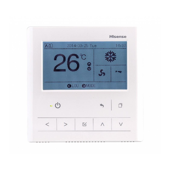
Hisense HYXE-J01H Service Handbook

Hisense HYXE-J01H Service Handbook

Control switch
Table of Contents

Advertisement

Qingdao Hisense Hitachi Air-conditioning Systems Co.,Ltd.
Add: Hisense Information Industry Park 218,Qianwangang Road,
Qingdao Economic Development Zone,China
Tel:+86-532-80879968 Fax:+86-532-80875929
Http: //www.hisensehitachi.com
E-mail: export@hisensehitachi.com
Specifications in this catalogue are subject to change without notice,in order that Hisense may bring the latest innovations to their customers.
TC2201702B
Control Switch
Technical and
Service Handbook
Models:
Central Control
HCCS-H128H2C1YM (Hi-Dom )
HCCS-H128H2C1NM (Hi-Dom )
Hyj-J01H (One Key Controler)
Hyjm-S01H(Central Controller)
TC2201702B
Wireless Remote Control Switch & Wireless Receiver
HYRE-T01H
HYRE-T02H
HYRE-V02H
HYRE-V01H
HYRE-X01H
(M-Concentrator)

Advertisement

Table of Contents
loading

Summary of Contents for Hisense HYXE-J01H

  • Page 1 HYRE-T02H E-mail: export@hisensehitachi.com HYRE-V02H HYRE-V01H HYRE-X01H Central Control Specifications in this catalogue are subject to change without notice,in order that Hisense may bring the latest innovations to their customers. (7-Day Timer) HYDE-E01H HYJE-D02H HCCS-H128H2C1YM (Hi-Dom ) HCCS-H128H2C1NM (Hi-Dom ) (M-Concentrator)
  • Page 2 IMPORTANT NOTICE AND SAFETY PRECAUTIONS G HISENSE pursues a policy of continuing improvement in design and performance of products. The right is therefore reserved to vary specifications without notice G HISENSE cannot anticipate every possible circumstance that might involve a potential hazard.
  • Page 3 < Signal Words > Signal words are used to identify levels of hazard seriousness. Definitions for identifying hazard levels are provided below with their respective signal words DANGER : DANGER indicates a hazardous situation which, if not avoided, will result in death or serious injury. WARNING : WARNING indicates a hazardous situation which, if not avoided, could result in death or serious injury.
  • Page 4 DANGER Do not perform installation work, refrigerant piping work, drain pump, drain piping and electrical wiring connection without referring to our installation manual. If the instructions are not followed, it may result in a water leakage, electric shock or a fire. Use the specified non-flamable refrigerant (R410A) to the outdoor unit in the refrigerant cycle.
  • Page 5 The standard utilization of the unit shall be explained in these instructions. Therefore, the utilization of the unit other than those indication in these instructions is not recommended.Please contact your local agent,as the occasion arises. HISENSE’s liability shall not cover defects arising from the alteration performed by a customer without HISENSE’s consent in a written form.
  • Page 6 NOTICE Do not install the indoor unit, outdoor unit, remote control switch and cable within approximately 3 meters from strong electromagnetic wave radiators such as medical equipment. Supply electrical power to the system to energize the oil heater for 12 hours before startup after a long shutdown.
  • Page 8 4. 7-Day Timer Display......................... 13 5. Central Control Display ......................14 6. Operation & Installation & Maintenance ................... 17 .HYXE-F01H ..........................17 .HYXE-G01H ..........................22 .HYXE-J01H ..........................35 .HYXE-M01H ..........................HYE-Q01 .............................72 .HYE-L01 ............................ 78 .HYE-W01 ............................... 83 .HYRE-T01/T02/V01/V02/V11/X01H.
  • Page 10 1.Control Switch Specifications Type Wired Remote Control Switch HYXE-F01H Model HYXE-G01H HYXE-J01H HYXE-M01H Run/Stop, Mode,Temp. Fan 6 Step Fan 6 Step Fan 3 Step Fan Speed Speed speed Air swing Speed /Auto Dehumidity Simple Timer Setting Days Timer Schedule Setting Check Mode ,...
  • Page 11 Wireless Receiver Type Wired Remote Control Switch E X01H Model (HYRE-T01H) Run/Stop, Mode,Temp. Fan speed Air swing Simple Timer Setting Use Wireless Receiver with Schedule Setting Wireless Remote Control Switch Emergency Check Mode , Operation:Cooling ,Heating al Setting Only Filter Reset Basic Unusual display Foun-...
  • Page 12 Type 7-Day Timer Central Station HYDE-E01H HYJE-D01H HYJE-D02H Model Run/Stop, Mode,Temp. Fan ○(3 Step Fan Speed) ○ 3 Step Fan Speed speed Air swing Simple Timer Setting × × Schedule Setting × × Check Mode , × × × × al Setting Filter Reset ○...
  • Page 13 Type Central Control HYJ-J01H HCCS-H247R4C1E HCCS-H128H2C1NM HCCS-H128H2C1YM Model Run/Stop, Mode,Temp. Fan ○(3 Step FanSpeed) ○(3 Step (3 Step ○ (Run/Stop) FanSpeed) FanSpeed) speed Air swing Simple Timer Setting × × × Schedule Setting ○ × ○ Check Mode , × ×...
  • Page 14 Wired Remote Control Switch 2.Wired Remote Control Switch Display Model:HYXE-F01H Display part For the instructions below, display is different from reality. Operating instructions display Temperature display display buttons function Operating mode Humidity Display display "no function" means doesn't hav e this function in indoor machine centralized control, when Timer using remote control is forbiddened...
  • Page 15 Wired Remote Control Switch Model:HYXE-G01H Display part For the instructions below, display is different from reality. Temperature display Remote wireless Operating mode signal receiver Humidity Display Operating instructions display display buttons function display "no function" means doesn't Units of working in test running hav e this function in indoor machine Display units connected in test running.
  • Page 16 Wired Remote Control Switch Model:HYXE-J01H...
  • Page 17 Wired Remote Control Switch Model:HYXE-M01H (To proceed with below instructions, all the displays are listed. It is different from actual running.) A Operation Button Section ⑤ON & OFF Button ①Fan Speed Button ⑥ Mode Button ②Timer Button ⑦ Temperature Button "+" ③Temperature Button "_"...
  • Page 18 Wireless Remote Control Switch Model: HYXE-Q01...
  • Page 19 Wireless Remote Control Switch Model: HYXE-L01 Transmitter Point the transmitter towards the receiver of the indoor unit when sending commands. The transmitting indication on the liquid crystal display flashes when sending commands. Transmitting Indication Liquid Crystal Display The set temperature, timer operation, position of air louver, operation mode, air flow mode, etc., are indicated.
  • Page 20 Wireless Remote Control Switch Model: HYE-W01 ● Wireless remote control is a device transmitting instructions on operation mode and time setting to indoor unit. Point the remote control to signal receiver on indoor unit and press relevant button to send IR signals for communication. ●...
  • Page 21 Wireless Receiver Kit Model: HYRE-T01H Model: HYRE-V01H HYRE-V11H Hole for Cable Switch "COOL" Switch "HEAT" EMERGENCY COOL FILTER HEAT TIMER Dip Switch (SW3) (Factory Setting) Printed Cover Base Circuit Board...
  • Page 22 7- Day Timer Model: HYDE-E01H...
  • Page 23 Central Control Model: HYJE-D02H The fi gure below shows all the indications for reference. Liquid Crystal Display Selection The actual display during operation is different. Indication of Indication of Indication of Indication of Setting Timer Demand Control Setting Target temperature Indication of Indication of Emergency Stop Fan Speed...
  • Page 24 Central Control Model: HCCS-H128H2C1YM HCCS-H128H2C1NM...
  • Page 25 Central Control Model: HCCS-H247R4C1E...
  • Page 26 Central Control Model: HYJ-J01H...
  • Page 27 Central Control Model: HYJM-S01H...
  • Page 28 WARNING DO NOT perform installation work and electrical wiring connection by yourself. Contact your distributor or  dealer of Hisense and ask them for installation work and electrical wiring by service person.    CAUTION DO NOT install the indoor unit, outdoor unit, controller and cable at such places as;...
  • Page 29 HYXE-F01H B.When Using Switch Box JIS box (field-supplied) Connect the terminals. Remove the protection film. Attach the remote control switch to the holding bracket.Be careful not to pinch the cable when attaching it. M4 Screws Remove the protection film from the liquid M4なべネジ...
  • Page 30 HYXE-F01H Optional Setting and Input / Output Setting of Indoor Unit Normal Mode (When unit is not operating) Selection of Indoor Unit for Optional Setting Change to the optional setting mode. "01" or "02" fashes. Press the “CHECK” switch and the ”RESET” switch simultaneously for more than 3 seconds.
  • Page 31 HYXE-F01H Sheet A Optional Setting Items Individual Setting Individual Setting Setting content setting Name Setting content setting Name setting item setting item 00:Not Available 01:Available Removal of Heating The power supply start stop 1 00:Standard 01:Removal Temperature Compensation 02:Set Temp.+2°C(*1) Not Prepared Not Used due to Uneven Heat Load...
  • Page 32 HYXE-F01H Elevating Grille Group Setting and Cancellation Group setting of the elevating grille refers to a function that allows all settings for the elevating grille(setting of elevating functions for input 2 and outputs 1 and 2) to be made all at once for all indoor units connected to the remote control switch.Setting are made by following the procedure as follows. Elevating Grille Group Setting Procedure Normal mode (when unit is not operating) Switch to the elevating grille group setting mode.
  • Page 33 HYXE-G01H ã äå æç èè éææ ê ë æìíè éæå î ìè è æêå ï ç æð ê ç ñ ò æ ç ñ ä è ìè é ó æ ë ô õ ô èè é æö ì è è ì ÷ ì í ø è é æé ì î ê ñ ä ë ö...
  • Page 34 HYXE-G01H...
  • Page 35 HYXE-G01H...
  • Page 36 HYXE-G01H Introduction Medical equipment with electromagnetic wavel, Please do not assemble at the following situation ● ● ・ Oil (including machine oil)foam spray, please do not put the signal face of electromatnetic wave with much steam directly to the remote control to avoid any misoperation. ・Place of vulcanization like hotspring To avoid the influence of electromagnetic wave, ・Place with combustible gas...
  • Page 37 HYXE-G01H Safety instruction Revolver Do not operating remote control using moist hand ● Might cause electric shock. Safety instruction: restart constantly or the revoler button is unusual, do shut main ● power supply at once. When abnormal happened, like scorched smell, do stop all running and shut down ●...
  • Page 38 HYXE-G01H Each part name Display part For the instructions below, display is different from reality. Temperature display Humidity display Humidity Operating mode Remote wireless signal receiver Units of working in test running Display units connected in test running. Operating instructions display This remote control only for operating on display buttons function display "no function"...
  • Page 39 HYXE-G01H Cooling Heating Dry (Auto) Fan Only "shop/office heat pump air conditioner" and “Heat pump for buildings have function of heating; "shop/ office cooling only unit" and " cooling only unit for buildings" are not. Plug in before operating, for protecting compressor.
  • Page 40 HYXE-G01H Press function button, selecting setting temperature 1 Display area flickering. △ Each press of button , temperature rises by 1 degree,the upper limit is 30 degree. ▽ Each press of button , temperature falls by 1 2 degree. Cooling Dry, Fan..lowest 19 Heating...lowest 17 Press function button, select 1...
  • Page 41 HYXE-G01H Air swing setting Attentions No display of air swing, if the indoor machine has no automatic air deflector. Press ` button, start up, then press function button, selects air swing 1 Display area flickering. W ind angle modifies in sequence by each pressing of △...
  • Page 42 HYXE-G01H Timer setting Function and operation ● Starting up timer..after setting time, starting ● Shutting down timer..after setting time, shutting down Starting up timer and shutdown timer could not be used combinedly. ● Under halted state and without starting up timer setting, press funtion button for 3 secs., Starting switch to the...
  • Page 43 HYXE-G01H Operating method Press button Operating light goes on Operating Start work. Temperature air swing setting After setting, the state will be saved. D o not need daily setting. Re-press button Operating light goes out. Quit Machine shut down. After heating stop,indoor units will be blowing for 2 mins.
  • Page 44 HYXE-G01H Other LCD display Status display ● CENTRAL display When remote control setting is forbidden by Centralized centralized controller, the remote control could not control be operated to change temperature, air swing and fan speed. Filter screen display ● Display the site of timing up of cleaning filter screen.
  • Page 45 HYXE-G01H Other LCD display Unusual display Operating light flickering ● LCD display the indoor address , system address and alarm code. ● Abnormal All display disappear ● W hen operating quit by power cut, start the controller after power on ●...
  • Page 46 HYXE-J01H...
  • Page 47 HYXE-J01H...
  • Page 48 HYXE-J01H...
  • Page 49 HYXE-J01H...
  • Page 50 HYXE-J01H...
  • Page 51 HYXE-J01H...
  • Page 52 HYXE-J01H...
  • Page 53 HYXE-J01H...
  • Page 54 HYXE-J01H...
  • Page 55 HYXE-J01H...
  • Page 56 HYXE-J01H...
  • Page 57 HYXE-J01H...
  • Page 58 HYXE-J01H...
  • Page 59 HYXE-J01H...
  • Page 60 HYXE-J01H...
  • Page 61 HYXE-J01H...
  • Page 62 HYXE-J01H...
  • Page 63 HYXE-J01H...
  • Page 64 HYXE-J01H...
  • Page 65 HYXE-J01H...
  • Page 66 HYXE-J01H...
  • Page 67 HYXE-J01H...
  • Page 68 HYXE-J01H...
  • Page 69 HYXE-J01H...
  • Page 70 HYXE-J01H...
  • Page 71 HYXE-J01H...
  • Page 72 HYXE-J01H...
  • Page 73 HYXE-J01H...
  • Page 74 HYXE-J01H...
  • Page 75 HYXE-J01H...
  • Page 76 HYXE-J01H...
  • Page 77 HYXE-M01H Introduction ● · ● · · · ● · ● ● Marks ● Shortcut ● ● Safety instruction ●   ● ● ● ● ● ●...
  • Page 78 HYXE-M01H ● ● ● Temperature Elementary operation...
  • Page 79 HYXE-M01H Fan speed ● Air swing setting...
  • Page 80 HYXE-M01H Air swing setting...
  • Page 81 HYXE-M01H Timer setting Function and operation Starting up timer..after setting time, starting Shutting down timer..after setting time, shutting down Starting up and shutdown timer could not be used combinedly Under halted state and without starting up timer setting, press TIMER button , switch to the timer setting and timer 7...
  • Page 82 HYXE-M01H Timer setting Other LCD display Status display Under state and without CENTRAL display starting up timer setting, press When remote control setting TIMER button , switch to the is forbidden by centralized timer setting and timer 7 controller, the remote control code display flickering.
  • Page 83 HYE-Q01...
  • Page 84 HYE-Q01...
  • Page 85 HYE-Q01...
  • Page 86 HYE-Q01 1 234 5 6 4 7 7 8 9 7 9 6 7 6 7 8 6    9  6  9 7  6 9 6  4  8 6 7 4 7 6 7 8 6  9 7    8  6  6 9  7 4   8  6 9 6 4 6   4  8 6  8  8 6 7 8  8 6  6 8   4  8    8 9 7 6  4  4 7 9  6 8  8  7  4  9 8 7  6 4  8     2 9  7 4   6 7 8 6  9 7    8  6 9 6 4 6   4  8 6  8  8 6 8  8  7  4  9 8 7  6 4  8  6 4  8 6 9 7 6  4  4 7 8  6   8  7  5 6 7 4   6 7 8 6 8  8  7   4    6 6 7 8 6 9   6  9 7 6 4 9  6 7 8 6  9 7    8  ...
  • Page 87 HYE-Q01 % 2L 8  4 7 8 6 7 8 6 K 8  7 6 X 9 6  5 6  9 7 9  6 7 8 6 7  4 9   7 7 8  6 7 4    6 7 8 6  8  8  8  6 6 7 8 6 9   6  9 7 6 4 9  6   8   6 7 8 N 6 6 6 6 6 6 XYMZ JK L3O 6   7   6 6 R 8 9 6 7 8 6  4 9   6 4  8 6  8  8  8  6  5 6 7 8 6 9   6  9 7 "...
  • Page 88 HYE-Q01...
  • Page 89 HYE-L01 Operation & Installation Manual for Wireless Remote Control Switch (Unidirectional Type) Model: Do not turn ON the power source, unless the preparation for test running is completed. G Read this manual carefully before installation work for correct performance. G Read this manual together with the “Installation & Maintenance Manual” for the indoor unit. G J is the blank box for checking.
  • Page 90 HYE-L01 Name of Parts G Controller: This controller is used to send commands about operation mode, timer setting, etc. to the indoor unit. Face the transmitter of the controller toward the receiver of the indoor unit and press the switch of required operation so that commands (by infrared rays) are sent to the indoor unit.
  • Page 91 HYE-L01 ATTENTION: In case that the indication lamp (yellow) does not turn ON although the commands are sent, the commands are not received by the indoor unit. In such a case, send the commands again. ATTENTION: The transmitter of the controller has the vertical directivity to the receiver, and the permissible angle for transmitting is within 50 .
  • Page 92 HYE-L01 7. Test Running by Controller ATTENTION: Test running by the controller can not be performed in case that the wired remote control switch is used together; in case that multiple units are operated simultaneously . In such cases, perform the test running by the wired remote control switch. J 1) Perform the test run after the installation work is completed.
  • Page 93 HYE-L01 <Procedures> ATTENTION: Turn OFF all the power source before the following procedures such as wiring, setting the rotary switch, etc. J 1) Installation of Air Panel for Wireless Control In case of simultaneous operation of plural (up to 16) units by the wireless remote control switch, apply the air panel for wireless control only to the unit to be operated, and apply the standard panels (for wired control) to other units.
  • Page 94 HYE-W01 Installation & Operation Manual for Wireless Remote Control HY -W01 To ensure correct use of this remote control, please read this manual carefully before use. This manual should be read along with the installation manual for air conditioner. Discrepancy of display will occur when: 1) ou press Sleep button while sleep function is unavailable in your indoor unit;...
  • Page 95 HYE-W01 4.Product Description ● Wireless remote control is a device transmitting instructions on operation mode and t i me setti n g to indoor uni t. Point the remote control t o s i nal receiver o n i n door unit a nd press relevant button to send IR signals for communication.
  • Page 96 HYE-W01 5. Signals Transmission * Send * As Tips ● S ● B 6. Operations ● D Caution •Direct sun • Oven ● T...
  • Page 97 HYE-W01 ■ Operation and other Functions ● Dehumidify ● room operation room ● ● Heating Air-supply Heat room o eration operation ● Automatic Cool or heat room operating Tips Power Tips utton Start Power Button Stop ( where indoor unit is not a DC dehumidifier) Button ( where indoor unit is a DC dehumidifier, it shall be used with HYRC- V02H/ photo diode) (Long press Mode +...
  • Page 98 HYE-W01 ■ Volume/Dir Point signal transmitter on remote control to the receiver and press the button. Tempe Each press on it will increase temperature by 1 . -rature (The maximum available temperature is 30 ) Each press on will reduce temperature by 1 .
  • Page 99 HYE-W01 ■ Operation and Functions ● Scheduled task means that the unit will be started or shut down when a time has elapsed. ● Scheduled -up or scheduled shutdown can be set. If the Timer button is pressed down when air conditioner is power-off, the unit will be when the set time has elapsed.
  • Page 100 HYE-W01 Saving/Mute/Sleep details consult your local dealer. When air conditioner is power-on: Point signal transmitter on remote control to Power the receiver and press the button. Air conditioner starts operation in power saving mode and the power saving icon is activated on the screen of remote control.
  • Page 101 HYE-W01 Strong button to strong heating mode operates in strong heating mode. ● ● ● 3D/S Strong airflow Stro airfl ● ● button to deactivate health mode. This function is available only in some models. ● ●...
  • Page 102 HYE-W01 7. Mounting Remote Control on Wall When the remote control is mounted on wall, keep it at least 30 cm...
  • Page 103 Wireless Receiver Kit Operation & Installation Manual for Wireless Receiver Kit HYRE-T01H HYRE-T02H HYRE-V01H HYRE-V02H HYRE-V11H  HYRE-X01H Model: Do NOT turn ON the power source, unless the preparation for test running is completed. G Read this manual carefully before installation work for correct performance. G Read this manual together with the “Installation & Maintenance Manual” for the indoor unit and ireless Remote Control Switch.
  • Page 104 Wireless Receiver Kit With Connection Cable Receiver Kit For Fixing Cab le Band For Fixing Receiv er Kit Scre w HYRE-V11H For Fixing Clamp Screw For Fixing Receiv er Kit Screw Screw For Fixing Receiv er Kit F or Fixing Cab le Clamp Communication With Expanded PCB...
  • Page 105 Wireless Receiver Kit 2. Installation of Wireless Receiver Kit HYRE-T01H  HYRE-T02H  NOTE: Install the receiver kit onto the air panel. 1 Install the wireless receiver kit,the indoor unit and the air panel at the same time. 2 Check to ensure that the distance between the wireless receiver kit and the EMI Source is larger than 3m.
  • Page 106 Wireless Receiver Kit Pay attention to the following installation procedures. If not, it may drop from the panel, resulting in a serious accident.
  • Page 107 Wireless Receiver Kit HYRE-V01H  HYRE-V02H  NOTE: Install the receiver kit onto the wall or ceiling near the indoor unit. Slot Cover 1) Install the wireless receiver kit and indoor unit at the same time. 2) In case that the wireless receiver kit is installed after installing the indoor unit, turn OFF the power source of the indoor unit.
  • Page 108 Wireless Receiver Kit (5)Remove the cover of indoor unit electrical control box and connect the cable to the terminals A and B of the terminal board (white). After connecting the cable, bind up the remaining cable length portion by band (Factory-Supplied) and put them in the electrical control box.
  • Page 109 Wireless Receiver Kit Then install the expanded PCB。 (2) Insert the cable into the rigid metal conduit. The install of expanded PCB refer to step (6). Cable (3) Fix the fixing bracket of kit by using screw (Field-Supplied). Cable Screw (Field-Supplied) This figure shows the case of Switch Box for 1 Controller. (4) Attach the cover same as A-(4).
  • Page 110 Wireless Receiver Kit (6)The install of expanded PCB : ● As shown in figure 1 below. Connect the  receiver kit to terminal CN23 of the expanded PCB.  expanded pcb torque 0.5N terminal CN23 Clamp Twisted Pair Inside of electrical box Outside of electrical box receiver kit Fig. 1 As shown in figure 2. In the electrical box there are four spare white supporting feet, arranging for 63 mm × 26 mm ●...
  • Page 111 Wireless Receiver Kit HYRE-X01H 1 Install the wireless receiver kit,the indoor unit and the air panel at the same time. 2 In case that the wireless receiver kit is installed after installing the indoor unit ,turn off the power source of the indoor unit and remove the air panel. 3 This receiver kit can be installed at the position of signal receiver corner plate.
  • Page 112 Wireless Receiver Kit ) 6 After the panel is installed, remove the receiver panel, as shown in figure A, and then install the signal receiver. 7 Draw out the connecting cable from the corner pocket and connect the connecting cable and the wire of the receive kit. After connecting the cable,wrap the connector with the cover and fix them with a band.
  • Page 113 Wireless Receiver Kit 2) Optional Setting for Dip Switch (SW3) Dip Switch Setting (SW3) Operation Function Setting of Sub Receiver Kit Identifying of Indoor Units : ON, : OFF H YRE-V11H HYRE-V01H  HYRE-V02H  、 、 Optional Function Setting Open the lid of cover so that the following functions are available. Hole for Cable Switch "COOL"...
  • Page 114 Wireless Receiver Kit 2) Optional Setting for Dip Switch (SW3) Dip Switch Setting (SW3) Operation Function Setting of Sub Receiver Kit Identifying of Indoor Units : ON, : OFF 4. Others 1) Proceed the “TEST RUN” mode by using “Operation & Installation Manual” for the wireless remote control switch.
  • Page 115 HYDE-E01H HYDE E01H Hisense...
  • Page 116 HYDE-E01H...
  • Page 117 HYDE-E01H...
  • Page 118 HYDE-E01H HYXE-A01H Hi-NET Hi-NET HYDE-E01H HYXE-A01H HYXE-A01H HYDE-E01H HYJE-D02H HYJE-D02H HYDE-E01H Hi-NET HYDE-E01H HYJE-D02H Hi-NET Hi-NET...
  • Page 119 HYDE-E01H HYJE-D02H HYXE-A01H HYXE-A01H HYXE-A01H HYXE-A01H HYJE-D02H HYJE-D02H HYJE-D02H...
  • Page 120 HYDE-E01H HYXE-A01H HYJE-D02H...
  • Page 121 HYDE-E01H...
  • Page 122 HYDE-E01H...
  • Page 123 HYDE-E01H...
  • Page 124 HYDE-E01H HYXE-A01H HYJE-D02H...
  • Page 125 HYDE-E01H HYXE-A01H HYJE-D02H...
  • Page 126 HYDE-E01H HYJE-D02H...
  • Page 127 HYDE-E01H...
  • Page 128 HYDE-E01H HYJE-D02H HYXE-A01H...
  • Page 129 HYDE-E01H Hisense HYXE-A01H HYJE-D02H HYJE-D02H Hisense...
  • Page 130 # DO NOT perform installation work and electrical wiring connection by yourself. Contact your distributor or dealer of Hisense and ask them for installation work and electrical wiring by service person. # When performing the insulation test, withstand voltage test and so on, ensure to remove the FG terminal connection of TB1.
  • Page 131 HYJE-D02H '2) Attach the power supply part to the switch box. '3) Attach the control part onto the power supply part. At fi rst, attach the upper side, and then the lower side. Do not run the power line and the control line through the same conduit tube.
  • Page 132 HYJE-D02H # DSW1 (Address Setting) Address Setting of DSW1 1 2 3 4 1 2 3 4 1 2 3 4 1 2 3 4 1 2 3 4 1 2 3 4 1 2 3 4 1 2 3 4 # Judgment of Hi-NET Adaptive When installing the central station, check whether the system is Hi-NET adaptive or non-adaptive, and set the DSW2-4 pin depending on the checking results.
  • Page 133 HYJE-D02H 4. Group Setting !Group and Zone Group...........Minimum Unit for Operation of Central Station One remote control switch group is considered as one group under the same control. The central station can control up to 64 groups (4 zones x 16 groups). Zone ..........Operation Unit with Plural Groups Up to 16 groups as maximum can be set in one zone.
  • Page 134 HYJE-D02H !Group Setting Procedure - The group setting consists of the master unit setting and the slave unit setting. The indoor unit, which is connected directly to the remote control switch, is set as the master unit, and the indoor unit connected with the transmission line is set as the slave unit.
  • Page 135 HYJE-D02H 4.1 Setting of Master Unit (1) Indication of Master Unit Setting Mode When the central station is changed to the master unit setting mode, the LCD indication on the central station is as shown below. The indication of the group to be set is fl ickered. The refrigerant cycle No. (hereafter called "Ref.
  • Page 136 HYJE-D02H ATTENTION: A. When the indication of Ref. No. is "- -", the indication of I.U. Add. is also "- -". In such a case, I.U. Add. can not be changed although the " " (TEMP) switch is depressed. B. Ref. No. with no indoor unit connected and I.U. Add. not connected are not indicated. C.
  • Page 137 HYJE-D02H 4.2 Setting of Slave Unit When using the remote control switch ( ) or receiver kit (HYRE-V01H), after the setting of master unit, the central HYXE‐A01H station automatically set the slave unit. Check for the setting state by the slave unit setting mode. (1) Indication of Slave Unit Setting Mode When the central station is changed to the slave unit setting mode, the LCD indication on the central station is as shown below.
  • Page 138 HYJE-D02H d. Select of Group To Be Set Depress the "GROUP" V switch, and the fl ickering indication of group No. is changed in order as shown below. ZONE GROUP CHECK The above fi gure shows the case of *The group, in which the master unit is not set, is not indicated. selecting Zone "2"...
  • Page 139 HYJE-D02H 5. Input / Output Function The central station has two input functions and two output functions as shown below. 1. Simultaneous Operation / Stoppage This function is for operating / stopping all the indoor units of the group, which is set by the central station, by the external contact signal.
  • Page 140 HYJE-D02H Demand Setting Procedure (1) Changing to Check Mode Depress the "CHECK" switch for more than 3 seconds, and the central station is changed to the check mode. *When there is any group in operation (with "RUN" indicator ON), the "CHECK" mode is not available. (2) Changing to Demand Setting Mode Depress the "CHECK"...
  • Page 141 HYJE-D02H (5) Setting Procedure Depress the "RUN/STOP" switch and the selected group is set with demand control, and the "!" and "DEMAND" indications appear. ZONE GROUP In the case where there is one or more group with demand setting in the CHECK zone, the "!"...
  • Page 142 HYJE-D02H # In case that the optional functions are set by the central station, it is required to set the same optional functions for the group by the remote control switch. # In case that the optional functions (items A – E as shown in Page 12) are set by the remote control switch, it is required to set the same optional functions for the group by the central station.
  • Page 143 HYJE-D02H Zone and Group Setting Table of Central Station(1) Indoor Unit Address 00 01 02 03 04 05 06 07 08 09 10 11 12 13 14 15 Fill the zone number (1-4) and the group number (1-16) in the above table. Circle the unit number of the master unit.
  • Page 144 HYJE-D02H Zone and Group Setting Table of Central Station(2) Remarks Remarks Zone Group Zone Group (ex. Room Name) (ex. Room Name)
  • Page 145 HYJE-D02H 8. Switch Names and Functions The fi gure below shows all the indications for reference. Liquid Crystal Display Selection The actual display during operation is different. Indication of Indication o Indication of Indication of Setting Setting Target Timer Demand Control temperature Indication of Indication of Emergency Stop...
  • Page 146 HYJE-D02H About Zone and Group The central station controls plural indoor units as a unit (one indoor unit is also available). The operation unit is as follows; Group...........Minimum Operation Unit for Central Station One remote control switch group is considered as one group under the same control.
  • Page 147 HYJE-D02H 9. Operation Procedure A. Setting Target Selection and Monitoring Operation Status The central station can control up to 64 groups by each group, each zone or simultaneously . ( The selected setting target can be operated and the unit operation status can be monitored.) ATTENTION: When changing the zone No.
  • Page 148 The above indications show the case of setting operation mode for "ZONE 3, GROUP 6". The same setting procedure shall be performed for other groups. Some operation modes can not be set according to the unit model. Contact to Hisense dealer or your distributor for details.
  • Page 149 HYJE-D02H C. Setting of Temperature, Fan Speed and Louver Angle ATTENTION: A. Do not touch the "CHECK" switch. The "CHECK" switch is only for service use. B. When the "CHECK" switch is depressed by a mistake and the central station is changed to the check mode, depress the "RESET"...
  • Page 150 HYJE-D02H In Case of 4-Way Cassette Type (Example) LCD Indication Approx. Approx. Approx. Approx. Approx. Approx. Approx. Air Louver Angle Recommnended COOL and DRY Angle Angle Range Recommnended HEAT Angle Angle Range NOTES: # The fi xing angle of the louver shown above is the case of 4-way cassette type indoor unit. The fi xing angle is different according to unit model.
  • Page 151 HYJE-D02H E. Prohibiting Operation by Remote Control Switch <Function> To prohibit the operation by the remote control switch. When this function is available, the "CENTRAL" indication appears on the LCD on the remote control switch and the operation by the remote control switch is not available. 1.
  • Page 152 During the emergency stoppage, indoor units are stopped and the operation by the remote control switch is not available. Contact your distributor or dealer of Hisense for details. <DEMAND> Turned ON The "DEMAND" is indicated when the demand input is set by the outside input function.
  • Page 153 Hi-Dom...
  • Page 154 Hi-Dom...
  • Page 155 Hi-Dom...
  • Page 156 Hi-Dom...
  • Page 157 Hi-Dom...
  • Page 158 Hi-Dom...
  • Page 159 Hi-Dom...
  • Page 160 Hi-Dom...
  • Page 161 Hi-Dom...
  • Page 162 Hi-Dom...
  • Page 163 Hi-Dom...
  • Page 164 Hi-Dom...
  • Page 165 Hi-Dom...
  • Page 166 Hi-Dom...
  • Page 167 Hi-Dom...
  • Page 168 HCCS-H247R4C1E M-Concentrator Model:HCCS-H247R4C1E Installation Configuration and Maintenance Manual Preamble ●This product is Schneider meter iEM 3150 and iEM 3350 meter readers. ●This product requires air conditioning and Hi-Dom gateway server (computer services software is installed, the computer needs local procurement) and with the use of Ethernet or the Internet. ●Do not install the machine in the following locations, such as the places filled with gas or oil droplets, prone to cause fire, deformation, corrosion and damage to the machine.
  • Page 169 HCCS-H247R4C1E 1.2 Name of meter adapter parts Figure 1.2 LED indicators 1.2.1 Description of LED indicators POWER Power display LED (red) it is on when the unit is power-on M-BUS M-BUS signal communication flashing when M-BUS signal is display LED (yellow) transmitted working status display (green) it is on when initialization and flashing...
  • Page 170 HCCS-H247R4C1E 1.2.2 Terminal marking instruction ① : Power input(DC12V)-------------Non-polarized ② : Power input(DC12V)-------------Non-polarized ③ : M-BUS signal input ---------------Non-polarized ④ : M-BUS signal input ---------------Non-polarized ⑤ : RS485 A ----------------------------positive ⑥ : RS485 B ----------------------------negative ⑦ :LAN interface ※DC12V and DC5V power supply can not simultaneously access. 1.3 Specifications of meter adapter Meter adapter specifications and LAN (Ethernet) communication specifications, see aircondition adapter related specifications.
  • Page 171 HCCS-H247R4C1E Figure 2.2 Wiring diagram of meter adapter Figure 2.2 meter adapter wiring diagram wiring specifications, see Table 2.1 Wiring Specification of meter adapter. Table 2.1 Wiring Specification of meter adapter Wiring type Voltage Usage of wiring Distance Cable specification of wiring Specification between lines...
  • Page 172 HCCS-H247R4C1E Enter the user name: admin, with no password, click on the login, the interface appears after login as shown in Figure 3.2. Figure3.2 Setting and debugging Click <Network Settings> into the IP settings interface, Please refer to ip setting of air condition adapter. Click <RS485 Settings>...
  • Page 173 HYJ-J01H...
  • Page 174 HYJ-J01H...
  • Page 175 HYJ-J01H...
  • Page 176 HYJ-J01H...
  • Page 177 HYJ-J01H...
  • Page 178 HYJ-J01H...
  • Page 179 HYJ-J01H...
  • Page 180 HYJ-J01H...
  • Page 181 HYJ-J01H...
  • Page 182 HYJ-J01H...
  • Page 183 A place of poorly ventilated. An acid or alkaline environment. If you have any questions, contact your HISENSE distributor or dealer. DO NOT install the indoor unit, outdoor unit, central controller and cable within approximately 3 meters from strong electromagnetic wave radiators such as medical equipment.
  • Page 184 HYJM-S01H 2 GENERAL DATA HYJM-S01H is the central controller for air conditioning system that controls and monitors maximum 160 indoor units. 2.1 MAIN FEATURES The following functions are available for the all indoor units which are connected to the central controller. Run/Stop, Operation Mode Change, Fan Speed Control, Swing Louver Direction Control, ECO mode, Temperature limitation, Temperature Setting and Permitting/Prohibiting Operation by Remote Control Switch.
  • Page 185 HYJM-S01H 2.2 DIMENSIONAL DATA Unit:mm Press inside button with a needle to reboot controller AC 100 ~240V input RS-485(Reserve) LAN(Reserve) For external output For external input H-NET 2.3 SPECIFICATION Model HYJM-S01H Outer Dimension <W x H x D + (Built-in Part)> 220x148x20+33(mm) Net Weight 0.68Kg(Approx.)
  • Page 186 HYJM-S01H 3 PART NAMES AND FUNCTIONS Front Side Color LCD Display with Touchscreen To operate and monitor the units through the touchscreen display.The touchscreen display will be automatically turned off when the touchscreen is not operated for the given length of time. Power Indicator To indicate the power condition of the central controller OFF (lamp): Power is turned OFF .
  • Page 187 HYJM-S01H When Unit Body is opened For terminating resistance It is used for transmission line recovery. Fuse for Power Supply Fuse for H-NET Transmission Line For protection of power For protection of H-NET transmission line circuit DANGER DO NOT remove the covers of marked with “ ”...
  • Page 188 HYJM-S01H 3.1.2 “AC Monitor(Block)” Bl ock Tab To change the monitor display into “Block” or Present Indication “All Groups” indication. To display the present indication (groups in block) Group Button To indicate the operating condition Green: Run Gray: Stop Red: Abnormal If the target group button is touched, “Settings”...
  • Page 189 HYJM-S01H 3.3 EXIT SERVICE MENU SCREEN Touch “Back” on “Service Menu” to return to AC Monitor (All Groups) or AC Monitor (Block). 3.4 QUI REFERENCE The table below shows the display on the screen and its function structure. Screen Display Function AC Monitor (All Groups) To display the name of all groups and operating conditions.
  • Page 190 HYJM-S01H 3.5 FUNCTIONS The table below shows the main functions. Operation Procedure Menu Function Display of All Groups (All the indoor central controllers.) Menu(Menu Items and Details) Display of Specified Block (All the remote control groups in the block Filter Sign Reset which are connected to the central controlle.) Simultaneous Run/Stop for All Group Schedule Operation...
  • Page 191 HYJM-S01H 4.3 SYSTEM CONFIGURATION This central controller (HYJM-S01H) is connected to H-NET and used for the central control and monitoring of the air conditioners. The system configuration example is shown in below. Outdoor Unit1 Remote Control Switch Wiring Transmission Wiring (H-NET) Remote Remote Control...
  • Page 192 HYJM-S01H 4.4.1 Preparation at the site Before installing a controller, prepare the following items. Parts Specification Switch Box Switch Box for 7” touchscreen(non-essential for Wall Surface Mouting) Power Supply Cable Cable SPEC: 0.75 mm Recommended Cable: 600V CV, CCV, CEV Cable SPEC: 0.75 mm Recommended Cable:Twist Pair Cable with Shield, H-NET Cable (For Control)
  • Page 193 HYJM-S01H 8. Install the battery as shown. Catch for fixing 9. Close the unit body until hearing snapping sound, and make sure if the top and bottom close fully. At this time, check if the top side cover is fixed and closed firmly. NOTE Top cover The life cycle of battery is 1-2 years.Please change the battery...
  • Page 194 HYJM-S01H 4.5 ELECTRICAL WIRING 1.This central controller (HYJM-S01H) requires wiring work of the power supply cable,air conditioner,and control wiring(H-NET). 2.Wiring Method. outdoor unit HYJM-S01H Connect the transmission wires to the H-NET terminals H-NET2 ①and② of the outdoor units H-NET1 1 2 3 4 5 6 and the indoor units.
  • Page 195 HYJM-S01H Use an earth leakage breaker with medium sensitivity, and an activation speed of 0.1 or less. If this is not fitted, there is a risk of electric shock and/or fire. Install an earth leakage breaker, fuse and circuit breaker for each outdoor unit power line. Not fitting it may cause an electric shock or fire.
  • Page 196 HYJM-S01H 5.1 LIST OF ITEMS Item Function Language Setting This function is used for language selection. Date&Time This function is used for adjusting the date and time. The connected indoor units are checked by the central controller in the same H-NET. This function is used for Group Register the group or block registration of them.
  • Page 197 HYJM-S01H 5.2 INITIAL POWER ACTIVATION SETTING Supply power to the Unit Turn on the power supply of the air conditioners. Perform after checking of each air conditioner has test run and confirming all the air conditioners operates normally. Turn on the power supply of the central controller. “Loading”...
  • Page 198 HYJM-S01H 5.5 GROUP REGISTER Register the indoor units confirmed for connection to the group (block) of the central controller. Confirm the number of the units. (When the power supply is turned ON at the first time.) Touch “Yes” on the touchscreen and the setting screen is displayed. Touch “No”...
  • Page 199 HYJM-S01H 5.5.1 GROUP REGISTER 1. Select “Group Register” on the screen of “Service Menu”. NOTE This function cannot be selected when the external input signal is input to the external input terminal 1 or 2. 1. Select group for unit to register. •...
  • Page 200 HYJM-S01H 4. Touch “OK” on “Group Register” to return the screen of “Service Menu”. 5.5.2 How to unregister group 1. Select “Group Register” on the screen of “Service Menu”. Refer to item How to register group. NOTE This function cannot be selected when the external input signal is input to the external input terminal 1 or 2. 2.
  • Page 201 HYJM-S01H 4. Touch “OK” to return to screen of “Service Menu”. 5.6 SCHEDULE OPERATION This function is used for the timer operation. The schedule setting is possible to set for the block and each group. Holiday setting that does not activate the schedule is also available.
  • Page 202 HYJM-S01H External Input/Output Terminals Specification Input Terminal: Non-voltage contact (normal open) for signal Input DC12V, 10mA. The switching of the contact is available. Pulse width is 100ms or more for pulse signal input. Output Terminal: Contact (voltage is applied) for signal Output DC12V. 1 Select “External Input/Output Setting”...
  • Page 203 HYJM-S01H 5.8 CONTACT INFORMATION REGISTER The contact information editing or registering for “Contact Info. Register” indication function. 1 Select “Service Phone Setting” on the screen of “Service Menu”. 2 Select “Contact Info. 1 Name Editing” or “Contact Info. 1 TEL. No. Editing” to register the information. 3 Select the characters to input from the keyboard.
  • Page 204 HYJM-S01H 5.9 ALARM HISTORY The alarm history record of the air conditioner and the central controller. The time of alarm occurrence, abnormal unit and alarm code are recorded, and the alarm history record deleting is performed by this function. Select “Alarm History” on the screen of “Service Menu”. “Alarm History”...
  • Page 205 HYJM-S01H 3. After several seconds, the screen is changed and the connection check of the system is started. 6 OPERATION PROCEDURE 6.1 DISPLAY OF ALL GROUPS 1. Touch “All Groups” on the touchscreen display. 2. All groups are displayed on the touchscreen. (All indoor units connected to the central controller will be indicated). Each operation status is indicated by color of the group button as follows: Green : Run Gray : Stop...
  • Page 206 HYJM-S01H 1. Select the target block from the screen of AC Monitor. AC Monitor (All Groups) AC Monitor (Block) 2. The groups in the selected block will be displayed on the touchscreen. Each operation status is indicated by color of the group button as follows: Green : Run Gray : Stop...
  • Page 207 HYJM-S01H 3. The confirmation screen will be displayed. Touch “OK” (All indoor units connected to the central controller will be simultane- ously operated) . Touch “Cancel” to cancel this command. 1. Select the target block from the touchscreen display to set simultaneous Run/Stop/ECO operation. 2.
  • Page 208 HYJM-S01H 6.5 RUN/STOP FOR EACH GROUP 1. Select the screen of “AC Monitor (All Groups)” or “AC Monitor (Block)”. Select the group to set by touching the group button. AC Monitor (All Groups) AC Monitor (Block) 2. Selected group setting will be indicated on the touchscreen display. Touch “RUN” or “STOP”. 3.
  • Page 209 HYJM-S01H 2. Slide the “OPE. MODE”, the operation mode will be changed alternately as follows. The “AUTO” (Heating/Cooling Automatic Operation) will be included as option if applicable. 3. Touch “OK” to confirm and return. 4. Touch “Cancel” to cancel the command and return. NOTE Some operation modes cannot be set depending on the unit model.
  • Page 210 HYJM-S01H 2. Slide the “FAN SPEED”, the fan speed setting will be changed alternately as follows. 3. Touch “OK” to confirm and return. 4. Touch “Cancel” to cancel the command and return. NOTE Actual fan speed during the dry operation will be “LOW” regardless of the fan speed setting. The figure above shows an example of standard unit.
  • Page 211 HYJM-S01H indication COOL Angle range HEAT Angle range : Auto swing operation will be started. 3. Touch “OK” to confirm and return. 4. Touch “Cancel” to cancel the command and return. NOTE • This function (swing louver direction) may not be set depending on the unit model. •...
  • Page 212 HYJM-S01H 3. Touch “OK” to confirm and return. 4. Touch “Cancel” to cancel the command and return. NOTE • The figure above shows an example of the setting temperature for the standard unit. The temperature setting range may be different depending on the connected indoor units. 6.10 PERMITTING/PROHIBITING OPERATION FROM REMOTE CONTROL SWITCH This function is used for prohibiting the operation from the remote control switch.
  • Page 213 HYJM-S01H NOTE • If the unit is started from the central controller it can be stopped from the remote control switch even while the operation from the remote control switch is prohibited. In this case, press “Run” on the remote control switch to start the operation again.
  • Page 214 HYJM-S01H 6.12 ECO START This function is used to operate the indoor unit according to the ECO setting. 1. Select the screen of “AC Monitor (All Groups)” or “AC Monitor (Block)”. Select the group to set by touching the group button. AC Monitor (All Groups) AC Monitor (Block) 2.
  • Page 215 HYJM-S01H 7 MENU The table below shows menu item and its function. Item Function This function is used for turning off the filter sign of the connected indoor units. Filter Sign Reset This function can be used only for the indoor unit with “Filter Sign”. This function is used for scheduled timer operation which is possible to set by each block or group.
  • Page 216 HYJM-S01H 2. The screen of “Menu” will be displayed. 3. Select the item from the screen of “Menu”. 4. Touch “Back” to return. 7.2 FILTER SIGN RESET 1 Select “Filter Sign Reset” from the screen of “Menu”. 2 Select the target (all groups, block or group) to reset the filter sign. Select “All Groups”...
  • Page 217 HYJM-S01H 4. Touch “Back” to return. 7.3 SCHEDULE OPERATION 7.3.1 GROUP REGISTER Timer Setting for Weekly Schedule 1 Select “Schedule Setting” from the screen of “Menu”. 2. Select “Schedule Timer Setting” from the screen of “Schedule Setting”. 3 Select the target (all groups, block or group). •...
  • Page 218 HYJM-S01H 6. Set the schedule time, run/stop operation and temperature. • Select the schedule item No. (1~10) and set the time. • Select “RUN” or “STOP”. • Set the temperature. • “- -” will be indicated when the time and temperature are not set. 7.
  • Page 219 HYJM-S01H Copying Schedule Setting by Days of Week 1 Select “Schedule Setting” from the screen of “Menu”. 2 Select “Schedule Timer Setting” from the “Schedule Setting”. 3 Select the target (all groups, block or group). 4 Touch “Copy Day of Week”. 5 Select the day of the week tabs to paste.
  • Page 220 HYJM-S01H 6 Select the groups to paste. 7 Touch “Paste” The schedule setting is copied. 8 If “Done” is touched, the screen will return to “Schedule Timer Setting”. Deleting Schedule Setting by day 1 Select “Schedule Setting” from the screen of “Menu”. 2 Select “Schedule Timer Setting”...
  • Page 221 HYJM-S01H 3 Select the groups or blocks to delete the setting. If the groups or blocks are selected, the mark of “ ” is indicated. Multiple selection of group and block are available for deleting . 4 Touch “Delete Setting” ,the confirmation screen will be displayed. Delete Setting 5 If “OK”...
  • Page 222 HYJM-S01H 4 Set the date to suspend the scheduled operation. The calendar will be forward/backward by touching “ ” or “ ”. By touching the date on the calendar, the “Holiday” is set with mark of “ ”. “Holiday Setting” is canceled by touching the same date again.
  • Page 223 HYJM-S01H (3) Block (3) Group (3) ALL Groups 7.4 DATE&TIME 1 Select “Date&Time” from the screen of “Menu”. 2 Slide the Date and Time to adjust them. 3 Touch “OK” to confirm and return. 4 Touch “Cancel” to cancel and return. NOTE Periodical clock adjustment is recommended.
  • Page 224 HYJM-S01H NOTE • Clean and wipe the display with dry and soft cloth. • For oil and fat on the touchscreen such as finger print marks, use diluted neutral detergent. Before cleaning, wring water out to dry. After that, again wipe the display with dry and soft cloth. •...
  • Page 225 HYJM-S01H NOTE The registrable number of letters are maximum 20 for the name of the group (block). If “ENTER” is pressed, the name is indicated in 2 lines (10 letters/line) on the touchscreen display. 7.6.2 Copying name of group (Block) 1 Select “Name Setting”...
  • Page 226 HYJM-S01H 7.7 SCREEN DISPLAY SETTING 7.7.2 Temperature unit setting 7.7.1 Adjusting backlight of touchscreen display 1 Select “Screen Display Setting” from the screen of “Menu”. 1 Select “Screen Display Setting” from the screen of “Menu”. 2 Select “Backlight” from the screen of “Screen Display 2 Select “Temperature Unit”...
  • Page 227 HYJM-S01H 7.8 LANGUAGE SETTING 1. Select “Language Setting” from the screen of “Menu”. 4. Touch “Export” to output the data of operation time. 5. Touch “Start” to export the “Accumulated Operation Time” to 2. The confirmation screen is displayed when selecting the the USB memory stick.
  • Page 228 HYJM-S01H 7.10 CONTACT INFORMATION 1. Select “Service Phone Setting” from the screen of “Menu”. The following information will be displayed: • Contact information • Block/group name of the latest alarm • Latest alarm code 2 Touch “Back” to return to the screen of AC Monitor. NOTE Without alarm occurrence, the name of the target block/group and the alarm code will not be indicated.
  • Page 229 HYJM-S01H Power Failure • The display is OFF. • Once the unit is stopped by the power failure, the unit will not start again after the power recovery. Perform the starting procedures again. • In case of instantaneous power failure within 2 seconds, the unit will automatically start again. Noise •...

Table of Contents