
Related Manuals for CAME AGTMTMVKIT


Summary of Contents for CAME AGTMTMVKIT
- Page 1 AGT V + MTM KIT FA01481M04 FA01481-EN – VAS/101 AGT V MTMV/01 IT Italiano EN English INSTALLATION MANUAL FR Français AGTMTMVKIT RU Pусский...
-
Page 2: Contents Of The Kit
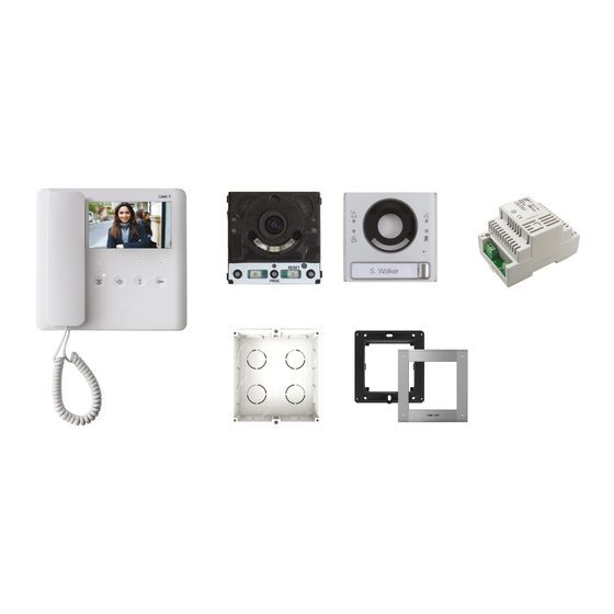
CONTENTS OF THE KIT AGT V – VAS/101 MTMV/01 General precautions Read the instructions carefully before beginning the installation and carry out the procedures as specifi ed by the manufacturer. • The product must be installed, programmed, commissioned and serviced by qualifi ed technicians, correctly trained with regard to •... -
Page 3: Technical Data
AGT V Description Internal video receiver. Function of terminals and jumpers Terminal board M1 BUS-line input Landing call – Alarm input Closing resistance (CL.RES) Master/slave selector (M/S) Technical data Type AGT V Power supply from BUS line (VDC) 15 to 20 Maximum consumption (mA) Consumption in stand-by mode (mA) -
Page 4: Installation
Installation Unhook the device from the metal support by press- • ① ing the plastic tab and sliding the device smoothly off the support Fix the wall support to the round Ø 60 mm recessed • , to the rectangular box 503 , or to the ②... -
Page 5: System Limits
System limits 4 monitors can be switched on simultaneously only in one- or two- family systems with entry panel X1+VA/01. N° Slave N° Master XDV/304 VAS/101 VCM/1D UTP CAT5 VCM/1D VCM/2D UTP/CAT 5 2x1mm 2 x 2.5 mm La+Lb ≤100 m –... - Page 6 Configuring melodies 3sec ... beep! ☞ Perform each of the following programming steps, in suc- cession: 1-Enter programming mode. Press and hold the button for 3 seconds. A short buzzing sound and a red fl ashing LED confi rm that you have entered pro- gramming mode 2-Programming the melody associated with the call from the entry panel.
- Page 7 Auxiliary contact max. 1A, 30V (AUX 2)* Protection rating (IP) * Factory settings. The contact can be programmed to perform diff erent functions. * Use BPT/CAME power supply units that are electronically pro- tected with maximum output current of 2.5 A.
-
Page 8: Button Numbering
REMOTE CONTROLLING CALL BUTTONS Manual configuration of terminals as call inputs 1 and 2 Short circuit the terminals ( ), press and hold the two call buttons on the unit, and power the device. The unit will restart. This indicates that the procedure has been completed successfully. Remove the short circuit and connect the additional N.O. -
Page 9: Entering Programming Mode
PROGRAMMING Programming for the first time Entering programming mode Press and hold the PROG button on the entry panel for at least 3 seconds and release within 6 seconds. The LEDs and the button LEDs fl ash to show the buttons are being programmed >3’’... -
Page 10: Programming Buttons
Programming buttons Press the fi rst call button on each module . The mod- ule stops fl ashing and remains on. Repeat for all the other call devices. a a , you do NOTE. For the basic module (no call buttons) not need to press the buttons that are shown as fl... -
Page 11: Exiting Programming
Programming the open-gate function An operator control can be connected to the module auxiliary relay and/or an operator status to the door status input. From applicable, preconfi gured internal receivers, the relay can >3’’ be controlled using the open-gate command and/or the operator status shown via the relevant LED on the internal receiver itself. - Page 12 Programming the entry panel video camera While programming the calls, the video camera’s fi eld of view can be adjusted from any receiver. To do this, lift the handset (where present) and press the “auto-connection ” button . From the default confi guration, scroll through the subsequent confi gurations pressing the AUX1 button or go back to the previous confi...
-
Page 13: Restoring Factory Settings
Enabling/disabling Press the PROG button on the entry panel and hold for at least 20 seconds The red and yellow LEDs fl ash quickly for 3 seconds NOTE: If the intercommunicating function is disabled, follow this procedure to enable it, and vice versa. The yellow LED comes on for 2 seconds to show the function has been enabled, or the red LED comes on for 2 seconds to show... - Page 14 VAS/101 Installation The power supply must always be installed horizontally. The device can be installed on DIN rails (EN 50022) on a suit- • able switchboard. See fi gure for dimensions. • NOTE. Ensure there is correct ventilation if the power supply is installed in a metal case.
- Page 15 This product complies with current applicable reference standards. DISPOSAL - Dispose of the packaging and the device at the end of its life cycle responsibly, in compliance with the laws in force in the country in which the product is used. The recyclable components are marked with a symbol and the material ID marker. THE DATA AND INFORMATION IN THIS MANUAL MAY BE CHANGED AT ANY TIME AND WITHOUT NOTICE.
- Page 16 CAME S.p.A. Via Martiri Della Libertà, 15 31030 Dosson di Casier - Treviso - Italy tel. (+39) 0422 4940 - fax. (+39) 0422 4941...
Need help?
Do you have a question about the AGTMTMVKIT and is the answer not in the manual?
Questions and answers