Table of Contents
Advertisement
Quick Links
Advertisement
Table of Contents

Related Manuals for Advantech USB-4716


Summary of Contents for Advantech USB-4716
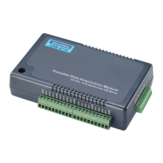
- Page 1 User Manual USB-4716 200 kS/s, 16-bit, USB Multifunction Module...
- Page 2 No part of this manual may be reproduced, copied, translated or transmitted in any form or by any means without the prior written permission of Advantech Co., Ltd. Information provided in this manual is intended to be accurate and reliable. How- ever, Advantech Co., Ltd.
- Page 3 Product Warranty (2 years) Advantech warrants the original purchaser that each of its products will be free from defects in materials and workmanship for two years from the date of purchase. This warranty does not apply to any products that have been repaired or altered by persons other than repair personnel authorized by Advantech, or that have been sub- ject to misuse, abuse, accident, or improper installation.
- Page 4 Technical Support and Assistance Visit the Advantech website at www.advantech.com/support to obtain the latest product information. Contact your distributor, sales representative, or Advantech customer service center for technical support if you need additional assistance. Please have the following information ready before calling: –...
- Page 5 In accordance with the IEC 704-1:1982 specifications, the sound pressure level at the operator’s position does not exceed 70 dB (A). DISCLAIMER: These instructions are provided in accordance with IEC 704-1 specifications. Advantech disclaims all responsibility for the accuracy of any statements contained herein. USB-4716 User Manual...
- Page 6 USB-4716 User Manual...
-
Page 7: Table Of Contents
Internal Pacer Trigger Connection ..........12 3.5.2 External Trigger Source Connection........... 12 Field Wiring Considerations ..............13 Appendix A Specifications ........15 Analog Input .................... 16 Analog Output ..................16 Non-Isolated Digital Input/Output ............17 Counter ....................17 General ....................17 USB-4716 User Manual... - Page 8 USB-4716 User Manual viii...
-
Page 9: Chapter 1 Introduction
This chapter will provide informa- tion on the features of the DAS module, a quick start guide for installation, and some brief infor- mation on software and accesso- ries for the USB-4716 Module. Section include: Features Software Overview... -
Page 10: Features
The Advantech Navigator is a utility that allows you to set up, configure and test your device, and later stores your settings in a proprietary database. To set up the I/O device for your card, you should first run the Advantech Navi- gator program (by accessing Start/Programs/Advantech Automation/DAQNavi/ Advantech Navigator). -
Page 11: Chapter 2 Installation
Chapter Installation Section include: Unpacking Driver Installation Hardware Installation Hardware Uninstallation... -
Page 12: Unpacking
Unpacking After receiving your USB-4716 package, please inspect its contents first. The pack- age should contain the following items: USB-4716 Module Startup Manual The USB-4716 Module harbors certain electronic components vulnerable to electro- static discharge (ESD). ESD could easily damage the integrated circuits and certain components if preventive measures are not carefully paid attention to. -
Page 13: Driver Installation
Driver Installation We recommend you install the software driver before you install the USB-4716 mod- ule into your system, since this will guarantee a smooth installation process. The driver package could be found on Advantech Support Portal (https://www.advan- tech.com/support). Search for the product model name on the support portal, then the corresponding driver/SDK package can be found. -
Page 14: Hardware Installation
Make sure you have installed the software driver before you install the module (please refer to Section 2.2 Driver Installation) After the driver installation is completed, you can now go on to install the USB-4716 module in any USB port that supports USB 2.0/3.0 standard, on your computer. -
Page 15: Chapter 3 Signal Connections
Chapter Signal Connections This chapter provides useful information on how to connect input and output signals to the USB-4716 via the I/O connectors. Sections include: Overview I/O Connectors Analog Input Connections Analog Output Connections Trigger Source Connections... -
Page 16: Overview
A good signal connection can avoid unnecessary and costly damage to your PC and other hard- ware devices. I/O Connectors USB-4716 is equipped with plug-in screw-terminal connectors that facilitate connec- tion to the module without terminal boards or cables. 3.2.1 Pin Assignment Figure 3.1 on next page shows the pin assignments for the five 10-pin I/O connectors... -
Page 17: I/O Connector Signal Description
Please refer to the following table for detailed LED indicator status information. Table 3.2: LED Indicator Status Description LED Status Description Device ready for work Device not ready to work Slow Blinking (5 times) Device initialization USB-4716 User Manual... -
Page 18: Analog Input Connections
Analog Input Connections USB-4716 supports 16 single-ended/8 differential (or combination) analog inputs. Each individual input channel is software-selected. 3.3.1 Single-ended Channel Connections The single-ended input configuration has only one signal wire for each channel, and the measured voltage (Vm) is the voltage of the wire as referenced against the com- mon ground. -
Page 19: Differential Input Connections
USB-4716. With this connection, the PGIA rejects a common-mode voltage Vcm between the signal source and USB-4716 ground, shown as Vcm in Figure 3.3. Note! In differential input mode, the input channel n should be used with chan- nel n+1. -
Page 20: Analog Output Connections (Voltage)
3.5.1 Internal Pacer Trigger Connection USB-4716 provides two 16-bit counters connected to a 10 MHz clock. Counter 0 is a counter that counts events from an input channel. Counter 1 is a 16-bit timer for pacer triggering. A low-to-high edge from the Counter 1 output will trigger an A/D conversion on USB-4716. -
Page 21: Field Wiring Considerations
Field Wiring Considerations When you use USB-4716 to acquire data from outside, noise in the environment might significantly affect the accuracy of your measurements if due precautions are not taken. The following measures will be helpful to reduce possible interfer- ence running signal wires between signal sources and USB-4716. - Page 22 USB-4716 User Manual...
-
Page 23: Appendix A Specifications
Appendix Specifications... -
Page 24: Analog Input
Single output Output Range 0~5, 0~10, ±5, ±10 V INLE ±2LSB Accuracy DNLE ±1LSB Slew Rate 0.125 V/µs Dynamic Performance Settling Time 150 µs (to ±1/2 LSB of FSB) Driving Capability 5 mA Output Impedance 0.1W max. USB-4716 User Manual... -
Page 25: Non-Isolated Digital Input/Output
360 mA @ +5.0V Typical Power Consumption 450 mA @ +5.0 V max. Operation 0~60° C (32~140° F) (refer to IEC 68-2-1, 2) Temperature Storage -20~70° C (-4~158° F) Relative Humidity 5~ 95% RH non-condensing (refer to IEC 68-2-1, 2) USB-4716 User Manual... - Page 26 USB-4716 User Manual...
- Page 27 USB-4716 User Manual...
- Page 28 USB-4716 User Manual...
- Page 29 USB-4716 User Manual...
- Page 30 No part of this publication may be reproduced in any form or by any means, such as electronically, by photocopying, recording, or otherwise, without prior written permission from the publisher. All brand and product names are trademarks or registered trademarks of their respective companies. © Advantech Co., Ltd. 2021...
Need help?
Do you have a question about the USB-4716 and is the answer not in the manual?
Questions and answers