Table of Contents
Advertisement
Quick Links
Advertisement
Table of Contents

Related Manuals for Advantech SOM-5893


Summary of Contents for Advantech SOM-5893
- Page 1 User Manual SOM-5893...
- Page 2 Because of Advantech’s high quality-control standards and rigorous testing, most of our customers never need to use our repair service. If an Advantech product is defec- tive, it will be repaired or replaced at no charge during the warranty period. For out- of-warranty repairs, you will be billed according to the cost of replacement materials, service time and freight.
- Page 3 Class I, Division 2, Groups A, B, C and D indoor hazards. Technical Support and Assistance Visit the Advantech website at http://support.advantech.com where you can find the latest information about the product. Contact your distributor, sales representative, or Advantech's customer service center for technical support if you need additional assistance.
- Page 4 Before setting up the system, check that the items listed below are included and in good condition. If any item does not accord with the table, please contact your dealer immediately. SOM-5893 CPU module 1 x Heatspreader (1960069427N001) SOM-5893 User Manual...
-
Page 5: Table Of Contents
Figure 3.18COM Port 4 Configuration ........28 Figure 3.19iManager - Hardware Monitor........29 Figure 3.20Serial Port Console Redirection ....... 30 Figure 3.21Network Stack ............31 Figure 3.22Intel i211 Gigabit Network Connection ..... 32 Figure 3.23NIC Configuration ............. 33 SOM-5893 User Manual... - Page 6 4.2.1 Windows 7 Driver Setup ............. 52 4.2.2 Other OSs................... 52 Advantech iManager ................53 Appendix A Assignment......... 55 SOM-5893 Type 6 Pin Assignments............56 Appendix B Watchdog Timer........ 61 Programming the Watchdog Timer ............62 Appendix C Programming GPIO......63 GPIO Register..................
-
Page 7: Chapter 1 General Information
Chapter General Information This chapter provides basic information about the SOM-5893 computer-on-module. Introduction Specifications Functional Block Diagram... -
Page 8: Introduction
Introduction SOM-5893 is a COM-Express basic pin-out Type 6 module that complies with the PICMG (PCI Industrial Computer Manufacturers Group) COM.0 R2.1 specification. The CPU module comprises a second-generation AMD embedded R-series APU, FCH A77E, and other peripheral chips to provide COM-specific functionalities. The latest AMD APU supports HeteoHSA. -
Page 9: Display
Expansion Interface PCI Express x16: Supports one PCIe x16 port (default) compliant to PCIe Gen3* (8.0 GT/s) specifications.Other combinations can be configured using the BIOS Setup utility. Please contact Advantech’s sales team for more information. Default Option 1 Option 2... -
Page 10: I/O
PCI Express x1: Supports seven PCIe x1 ports (default) compliant to PCIe Gen2* (5.0 GT/s) specifications. Other combinations can be configured using the BIOS Setup utility. Please contact Advantech’s sales team for more details. Default Option 1 Option 2 Audio Interface: HD audio interface ... -
Page 11: Functional Block Diagram
(up to 2 PCIe x1 when remove GIGA LAN) 8 USB 2.0 HD Audio 4 SATA 3.0 4 USB3.0 AMD A77E FCH 4 PCIe x1 LPC Bus TPM1.2 iManager (Option) WDT/GPIO/I RS1/RS2/FAN SMBus SPI Bus EFI BIOS SOM-5893 User Manual... - Page 12 SOM-5893 User Manual...
-
Page 13: Chapter 2 Mechanical Information
Chapter Mechanical Information This chapter gives mechanical information on the SOM-5893 CPU computer-on-module. Board Information Mechanical Drawing Assembly Drawing... -
Page 14: Board Information
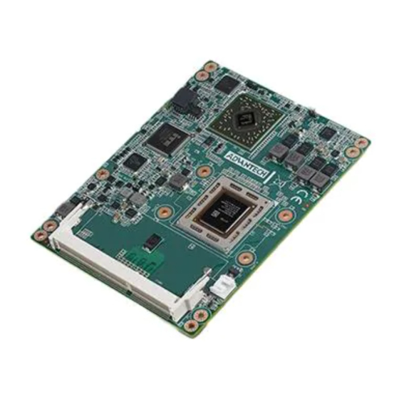
Board Information The figures below indicate the main chips on SOM-5893 Computer-on-Module. Please aware of these positions while designing your own carrier board to avoid mechanical and thermal problems; keep in mind best heat dispassion performance. On-Module Smart Fan Connector... -
Page 15: Mechanical Drawing
Mechanical Drawing For more detail about 2D/3D models, please see the Advantech COM support ser- vice website http://com.advantech.com. 55.38 29.98 Figure 2.3 Board Mechanical Drawing - Front 79.38 12.58 Figure 2.4 Board Mechanical Drawing - Back SOM-5893 User Manual... -
Page 16: Assembly Drawing
These figures demonstrate the assembly order, from the thermal module, to the COM module, to the carrier board. Figure 2.5 Assembly Drawing There are 4 reserved screw holes for SOM-5893 to be pre-assembled with the heat spreader. Figure 2.6 Heatspreader Pre-assembly... -
Page 17: Chapter 3 Ami Bios
Chapter AMI BIOS This chapter gives BIOS setup information for the SOM-5893 CPU computer-on-module. Introduction Entering Setup Hot / Operation Key Exit BIOS Setup Utility... -
Page 18: Introduction
Introduction SOM-5893 BIOS has been stored in a flash ROM which is inserted into a BIOS socket on the board. With the BIOS Setup program, users can modify BIOS settings and control various system features. This chapter describes the basic navigation of the SOM-5893 BIOS setup screens. -
Page 19: Entering Setup
System Date using the <Arrow> keys. Enter new values through the key- board. Press the <Tab> key or the <Arrow> keys to move between fields. The date must be entered in MM/DD/YY format. The time must be entered in HH:MM:SS format. System Date: mm/dd/yyyy System Time: hh/mm/ss SOM-5893 User Manual... -
Page 20: Advanced Bios Features Setup
3.2.2 Advanced BIOS Features Setup Select the Advanced tab from the SOM-5893 setup screen to enter the Advanced BIOS Setup screen. Users can select any item in the left frame of the screen, such as CPU Configuration, to go to the sub menu for that item. Users can display an Advanced BIOS Setup option by highlighting it using the <Arrow>... - Page 21 ACPI Sleep State This item allows users to select the ACPI sleep state. The system will enter when the SUSPEND button is pressed. Lock Legacy Resources This item allows users to enable or disable Lock of Legacy Resources. SOM-5893 User Manual...
- Page 22 3.2.2.2 Trusted Computing Figure 3.5 Trusted Computing TPM Support Disable/Enable TPM, if available. SOM-5893 User Manual...
- Page 23 CPB Mode This item allows users to auto or disable CPB Mode. C6 Mode This item allows users to enable or disable C6 Mode. Node 0 Information View Memory information related to Node 0. SOM-5893 User Manual...
- Page 24 Figure 3.7 Node 0 Information 3.2.2.4 IDE Configuration (SATA port) Figure 3.8 IDE Configuration SOM-5893 User Manual...
- Page 25 This item allows users to select to DP mode or HDMI mode. DDI1 OutputMode This item allows users to select to DP mode or HDMI mode. DDI2 OutputMode This item allows users to select to DP mode or HDMI mode. SOM-5893 User Manual...
- Page 26 This item allows users to select SDIO Access Mode. Auto Option: Access SD device in DMA mode if controller support it, otherwise in PIO mode. DMA Option: Access SD device in DMA mode. PIO Option: Access SD device in PIO mode. SOM-5893 User Manual...
- Page 27 Maximum time the device will take before it properly reports itself to the Host controller. "Auto" uses default value: for a Root port it is 100ms, for a Hub port the delay is taken from Hub descriptor. SOM-5893 User Manual...
- Page 28 This item allows user to set Parameters of COM Port 1. COM Port 2 Configuration This item allows user to set Parameters of COM Port 2. Parallel Port Configuration This item allows user to set Parameters of Parallel Port (LPT/LPTE). SOM-5893 User Manual...
- Page 29 COM Port 1 Configuration Figure 3.13 COM Port 1 Configuration – COM Port COM Port 1 enable or disable. – Change settings COM port 1 IRQ/IO/mode resources configuration. Users can select an optional setting for Super IO device. SOM-5893 User Manual...
- Page 30 COM Port 2 Configuration Figure 3.14 COM Port 2 Configuration – COM Port COM Port 2 enable or disable. – Change settings COM port 2 IRQ/IO/mode resources configuration. Users can select an optional setting for Super IO device. SOM-5893 User Manual...
- Page 31 This item allows users to enable or disable Parallel Port (LPT/LPTE). – Change settings This item allows users to select an optimal setting for Super IO device. – Device Mode This item allows users to change the Printer Port mode. SOM-5893 User Manual...
- Page 32 Set parameter of series port 3 (COM3) refer to PICMG SER0_TX / SER0_RX. COM Port 4 (SER1) Configuration Set parameter of series port 4 (COM4) refer to PICMG SER1_TX / SER1_RX. Hardware Monitor This item allows users to monitor hardware status. SOM-5893 User Manual...
- Page 33 Figure 3.17 COM 3 Configuration – COM Port COM Port 3 enable or disable. – Change settings COM port 3 IRQ/IO/mode resources configuration. Users can select an optional setting for Super IO device. – Device Mode Select the COM port mode. SOM-5893 User Manual...
- Page 34 – COM Port 4 COM Port 4 enable or disable. – Change settings COM port 4 IRQ/IO/mode resources configuration. Users can select an optional setting for Super IO device. – Device Mode Select the COM port mode. SOM-5893 User Manual...
- Page 35 iManager - Hardware Monitor This item monitor hardware status. Figure 3.19 iManager - Hardware Monitor SOM-5893 User Manual...
- Page 36 3.2.2.10 Serial Port Console Redirection Figure 3.20 Serial Port Console Redirection Console Redirection This item allows users to enable or disable console redirection for Microsoft Windows Emergency Management Serivces (EMS). SOM-5893 User Manual...
- Page 37 3.2.2.11 Network Stack Figure 3.21 Network Stack Network Stack This item allows users to enable or disable UEFI Network Stack. SOM-5893 User Manual...
- Page 38 Intel i211 Gigabit Network Connection Figure 3.22 Intel i211 Gigabit Network Connection NIC Configuration Configure boot protocol, Wake on LAN, Link Speed, and VLAN. Blink LEDs Identify the physical network port by blinking the associated LED. SOM-5893 User Manual...
- Page 39 Figure 3.23 NIC Configuration Link Speed Specifies the port speed used for the selected boot protocol. Wake on LAN This item allows users to enable or disable the server to be powered on using an in-band magic packet. SOM-5893 User Manual...
-
Page 40: Chipset
3.2.3 Chipset Select the Chipset tab from the SOM-5893 setup screen to enter the Chipset BIOS Setup screen. You can display a Chipset BIOS Setup option by highlighting it using bthe <Arrow> keys. All Plug and Play BIOS Setup options are described in this sec- tion. - Page 41 This item allows users to enable or disable integrate graphics controller. PSPP policy This item allows users to select PCIe Speed power policy. LCD Panel Type This item allows users to select LCD panel used by internal graphics device by selecting the appropriate setup item. SOM-5893 User Manual...
- Page 42 3.2.3.2 South Bridge Figure 3.26 South Bridge Restore on AC Power Loss This item allows users to select the options of Restore on AC Power Loss. SOM-5893 User Manual...
- Page 43 (Native IDE /n RAID /n AHCI /n AHCI /n Legacy IDE /n IDE AHCI /n Hyper- Flash) Onchip IDE mode This item allows users to select Legacy mode or Native mode. SATA IDE Combined Mode This item allows users to enable or disable SATA IDE Combined Mode. SOM-5893 User Manual...
- Page 44 SB USB Configuration Figure 3.28 SB USB Configuration This page helps users to enable and set up XHCI. SOM-5893 User Manual...
- Page 45 SB SD Configuration Figure 3.29 SB SD Configuration This page helps users to select the options of SD. SOM-5893 User Manual...
- Page 46 SB GPP Port Configuration Figure 3.30 SB GPP Port Configuration This page helps users to select the options for SB GPP Port Config. SOM-5893 User Manual...
- Page 47 SB HD Azalia Configuration Figure 3.31 SB HD Azalia Configuration This page helps users to select the options for SB HD Azalia. SOM-5893 User Manual...
- Page 48 3.2.3.3 North Bridge Figure 3.32 North Bridge SOM-5893 User Manual...
- Page 49 This option allows users to enable or disable Channel Interleaving. Memory Clear This option allows users to enable or disable Memory Clear function. Memory ECC This option allows users to enable or disable memory ECC. SOM-5893 User Manual...
- Page 50 Socket 0 Information Figure 3.34 Socket 0 information SOM-5893 User Manual...
-
Page 51: Boot Settings
If enabled, an OEM Logo is shown instead of POST messages. Fast Boot This item allows users to enable or disable boot with initialization of a minimal set of devices required to launch active boot option. Has no effect for BBS boot options. SOM-5893 User Manual... - Page 52 Option ROM Messages This item allows uses to select option ROM message. InT19 Trap Response BIOS reaction on INT19 trapping by Option ROM: IMMEDIATE – execute the trap right away; POSTPONED – execute the trap during legacy boot. SOM-5893 User Manual...
- Page 53 Launch Video OpROM policy This item controls the execution of UEFI and legacy Video OpROM. Other PCI device ROM priority For PCI devices other than Network, Mass storage or video defines which OpROM to launch. SOM-5893 User Manual...
-
Page 54: Security Setup
Setup options, such as password protection, are described in this section. To access the sub menu for the following items, select the item and press <Enter>: Change Administrator / User Password: Select this option and press <ENTER> to access the sub menu, and then type in the password. SOM-5893 User Manual... -
Page 55: Save & Exit
Restore Defaults The SOM-5893 automatically configures all setup items to optimal settings when users select this option. Optimal Defaults are designed for maximum sys- tem performance, but may not work best for all computer applications. In partic- SOM-5893 User Manual... - Page 56 BIOS setup menu. Restore User Defaults The users can select this option to restore user defaults. Launch EFI Shell from filesystem device Attempts to Launch EFI Shell application from one of the available filesystem devices. SOM-5893 User Manual...
-
Page 57: S/W Introduction
Chapter S/W Introduction and Installation S/W Introduction Driver Installation Advantech iManager... -
Page 58: Driver Installation
S/W Introduction The mission of Advantech Embedded Software Services is to "Enhance quality of life with Advantech platforms and Microsoft Windows embedded technology." We enable Windows Embedded software products on Advantech platforms to more effectively support the embedded computing community. Customers are freed from the hassle of dealing with multiple vendors (hardware suppliers, system integrators, embedded OS distributor) for projects. -
Page 59: Advantech Imanager
It makes these embedded features easier to integrate, speed up develop- ing schedule, and provide the customer's software continuity while upgrade hard- ware. For more details of how to use the APIs and utilities, please refer to Advantech iManager 2.0 Software API User Manual. - Page 60 SOM-5893 User Manual...
-
Page 61: Assignment
Appendix Pin Assignment This appendix gives you the infor- mation about the hardware pin assignments of the SOM-5893 CPU computer-on-module. SOM-5893 Type 6 Pin Assign- ments... -
Page 62: Som-5893 Type 6 Pin Assignments
SOM-5893 Type 6 Pin Assignments This section gives SOM-5893 pin assignments on COM Express connector, which are compliant with COMR.0 R2.1 Type 6 pin-out definitions. For more detail about how to use these pins and get design reference, please contact Advantech for the design guide, checklist, reference schematic, and other hardware/software support. - Page 63 PCIE_RX0+ PCIE_TX0- PCIE_RX0- LVDS_A0+ LVDS_B0+ LVDS_A0- LVDS_B0- LVDS_A1+ LVDS_B1+ LVDS_A1- LVDS_B1- LVDS_A2+ LVDS_B2+ LVDS_A2- LVDS_B2- LVDS_VDD_EN LVDS_B3+ LVDS_A3+ LVDS_B3- LVDS_A3- LVDS_BKLT_EN LVDS_A_CK+ LVDS_B_CK+ LVDS_A_CK- LVDS_B_CK- LVDS_I2C_CK LVDS_BKLT_CTRL LVDS_I2C_DAT VCC_5V_SBY GPI3 VCC_5V_SBY RSVD VCC_5V_SBY RSVD VCC_5V_SBY PCIE0_CK_REF+ BIOS_DIS1# SOM-5893 User Manual...
- Page 64 VCC_12V A106 VCC_12V B106 VCC_12V A107 VCC_12V B107 VCC_12V A108 VCC_12V B108 VCC_12V A109 VCC_12V B109 VCC_12V A110 B110 SOM-5893 Row C,D USB_SSRX0- USB_SSTX0- USB_SSRX0+ USB_SSTX0+ USB_SSRX1- USB_SSTX1- USB_SSRX1+ USB_SSTX1+ USB_SSRX2- USB_SSTX2- USB_SSRX2+ USB_SSTX2+ USB_SSRX3- USB_SSTX3- USB_SSRX3+ USB_SSTX3+ DDI1_PAIR6+ DDI1_AUX+...
- Page 65 PEG_RX0+ PEG_TX0+ PEG_RX0- PEG_TX0- TYPE0# PEG_LANE_RV# PEG_RX1+ PEG_TX1+ PEG_RX1- PEG_TX1- TYPE1# TYPE2# PEG_RX2+ PEG_TX2+ PEG_RX2- PEG_TX2- PEG_RX3+ PEG_TX3+ PEG_RX3- PEG_TX3- RSVD RSVD RSVD RSVD PEG_RX4+ PEG_TX4+ PEG_RX4- PEG_TX4- RSVD PEG_RX5+ PEG_TX5+ PEG_RX5- PEG_TX5- PEG_RX6+ PEG_TX6+ PEG_RX6- PEG_TX6- SOM-5893 User Manual...
- Page 66 D100 C101 PEG_RX15+ D101 PEG_TX15+ C102 PEG_RX15- D102 PEG_TX15- C103 D103 C104 VCC_12V D104 VCC_12V C105 VCC_12V D105 VCC_12V C106 VCC_12V D106 VCC_12V C107 VCC_12V D107 VCC_12V C108 VCC_12V D108 VCC_12V C109 VCC_12V D109 VCC_12V C110 D110 SOM-5893 User Manual...
-
Page 67: Watchdog Timer
Appendix Watchdog Timer This appendix gives you the infor- mation about the watchdog timer programming on the SOM-5893 CPU computer-on-module. Watchdog Timer Programming... -
Page 68: Programming The Watchdog Timer
BIOS, and then sets to EC. Only Win XP, Win7 and Win8 support it. In other OSs, it will still use an IRQ number from BIOS setting as usual. For details, please refer to iManager & Software API User Manual: SOM-5893 User Manual... -
Page 69: Programming Gpio
Appendix Programming GPIO This Appendix gives an illustra- tion of General Purpose Input and Output pin settings. System I/O Ports... -
Page 70: Gpio Register
GPIO Register GPIO Byte Mapping H/W Pin Name BIT0 GPO0 BIT1 GPO1 BIT2 GPO2 BIT3 GPO3 BIT4 GPI0 BIT5 GPI1 BIT6 GPI2 BIT7 GPI3 For details, please refer to iManager & Software API User Manual. SOM-5893 User Manual... -
Page 71: System Assignments
Appendix System Assignments This appendix gives you informa- tion about the system resource allocations on the SOM-5893 CPU computer-on-module. System I/O ports DMA Channel Assignments Interrupt Assignments 1st MB Memory Map... -
Page 72: System I/O Ports
AMD SATA Controller 0x0000F180-0x0000F183 AMD SATA Controller 0x0000F170-0x0000F177 AMD SATA Controller 0x0000F160-0x0000F163 AMD SATA Controller 0x0000F150-0x0000F15F AMD SATA Controller 0x00000040-0x00000043 System timer 0x0000029C-0x0000029D Motherboard resources 0x0000D000-0x0000DFFF PCI Express standard Root Port 0x00000063-0x00000063 Motherboard resources 0x00000065-0x00000065 Motherboard resources SOM-5893 User Manual... - Page 73 Direct memory access controller 0x0000C000-0x0000CFFF PCI Express standard Root Port 0x00000170-0x00000177 ATA Channel 1 0x00000376-0x00000376 ATA Channel 1 0x0000F100-0x0000F10F AMD PCI IDE Controller 0x00000378-0x0000037F ECP Printer Port (LPT1) 0x00000778-0x0000077F ECP Printer Port (LPT1) 0x000000F0-0x000000FF Numeric data processor SOM-5893 User Manual...
-
Page 74: Dma Channel Assignments
SDA Standard Compliant SD Host Controller & High Defini- IRQ 16 tion Audio Controller IRQ 17 Standard Enhanced PCI to USB Host Controller IRQ 18 Standard OpenHCD USB Host Controller IRQ 19 AMD SATA Controller IRQ 27 High Definition Audio Controller SOM-5893 User Manual... -
Page 75: 1St Mb Memory Map
0xFEC10000-0xFEC10FFF Motherboard resources 0xFF000000-0xFFFFFFFF Motherboard resources 0xFED00000-0xFED003FF High precision event timer 0xFEB6C000-0xFEB6C0FF SDA Standard Compliant SD Host Controller 0xFEB6E000-0xFEB6E0FF Standard Enhanced PCI to USB Host Controller 0xFEB6A000-0xFEB6BFFF AMD USB 3.0 Host Controller 0xFEB64000-0xFEB67FFF High Definition Audio Controller SOM-5893 User Manual... - Page 76 No part of this publication may be reproduced in any form or by any means, such as electronically, by photocopying, recording, or otherwise, without prior written permission from the publisher. All brand and product names are trademarks or registered trademarks of their respective companies. © Advantech Co., Ltd. 2015...
Need help?
Do you have a question about the SOM-5893 and is the answer not in the manual?
Questions and answers