Table of Contents
Advertisement
Available languages
Available languages
Quick Links
O p e r a t i o n sMa n u a l
O p é r a t i o n sMa n u e l l e s
B e t r i e b eMa n u e l l
H e t H a n d b o e kv a nv e r r i c h t i n g e n
F u n z i o n a me n t i Ma n u a l i
O p e r a c i o n e sMa n u a l e s
O p e r a ç õ e sMa n u a i s
O p e r a ç õ e sMa n u a i s
Me d i c a l
®
T r i o
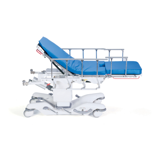
Mo b i l eS u r g e r yP l a t f o r m
Mo d e l 1 0 3 3
Advertisement
Chapters
Table of Contents

Subscribe to Our Youtube Channel
Related Manuals for Stryker Medical Trio 1033


Summary of Contents for Stryker Medical Trio 1033
- Page 1 O p e r a t i o n sMa n u a l Me d i c a l O p é r a t i o n sMa n u e l l e s B e t r i e b eMa n u e l l H e t H a n d b o e kv a nv e r r i c h t i n g e n F u n z i o n a me n t i Ma n u a l i O p e r a c i o n e sMa n u a l e s...
- Page 3 O p e r a t i o n sMa n u a l Me d i c a l O p é r a t i o n sMa n u e l l e s B e t r i e b eMa n u e l l H e t H a n d b o e kv a nv e r r i c h t i n g e n F u n z i o n a me n t i Ma n u a l i O p e r a c i o n e sMa n u a l e s...
-
Page 4: Table Of Contents
Table of Contents Introduction Specifications ................Warning/Caution/Note Definition . -
Page 5: Introduction
Introduction INTRODUCTION This manual is designed to assist you with the operation of the Model 1033 Trio Mobile Surgery Platform. Read it thoroughly before using the equipment. SPECIFICATIONS Maximum Weight Capacity 500 pounds Patient Surface Length / Width 78”/27” Overall Length / Width 80”... - Page 6 Introduction Before operating this unit, it is important to read and understand all information in this manual. Carefully read and strictly follow the warnings and cautions listed on this page. WARNING Injury could result if the table moves during procedures or examinations or while a patient is getting on or off the table.
-
Page 7: Operation Guide
Operation Guide APPLYING THE BRAKE SYSTEM NOTE For user convenience and ease of operation, there are brake/steer pedals on both sides of the base. To engage the brakes, push fully down on the side of the brake/steer pedal marked with the red label. To disengage the brakes, push down on the side of the brake/steer pedal marked with the green label until the brakes release and the pedal is in the neutral position (parallel with the floor). -
Page 8: Applying The Steer System
Operation Guide APPLYING THE STEER SYSTEM NOTE For user convenience and ease of operation, there are brake/steer pedals on both sides of the base. There is a retractable steering (pivot) wheel under the base hood at the center of the base assembly that increases the maneuverability of the surgery platform when transporting a patient along a straight line and when pivoting at corners. -
Page 9: Raising And Lowering Litter Height
Operation Guide RAISING AND LOWERING LITTER HEIGHT To raise the litter height, depress and release the litter up pedal (A) repeatedly until the desired height is reached. To lower the litter height, depress and hold down the litter down pedal (B). Release the pedal when the litter is at the desired height. -
Page 10: Operating The Fowler
Operation Guide OPERATING THE FOWLER To raise the Fowler, squeeze the red handle under the Fowler for pneumatic assist in lifting the Fowler to the desired height. Remove your hand(s) from the handle when the desired height is achieved. To lower the Fowler, squeeze the red handle and push down on the Fowler until it has reached the de- sired height. -
Page 11: Operating The Foot Section
Operation Guide OPERATING THE FOOT SECTION To lower the foot section, with one hand, squeeze the foot section up/down release handle at the side of the foot end of the litter. With the other hand, push down on the foot section to move it to the desired angle. - Page 12 Operation Guide OPERATING THE FOOT SECTION (CONTINUED) To remove the foot section for pelvic and lower body procedures, squeeze the red handles under the foot section on both sides and lift the foot section from the two receptacles at the end of the seat. To mount the foot section, tilt the foot section and insert the two arms into the litter receptacles.
-
Page 13: Trendelenburg/Reverse Trendelenburg Positioning
Operation Guide TRENDELENBURG/REVERSE TRENDELENBURG POSITIONING WARNING To avoid patient falls and injury, always use proper patient restraints when positioning the litter in Trendelen- burg or reverse Trendelenburg. For Trendelenburg positioning (head down), turn the hand crank (A), located at the head end of the unit, counterclockwise. -
Page 14: Lateral Tilt Positioning
Operation Guide LATERAL TILT POSITIONING CAUTION To avoid damage, move any equipment that may hinder motion before lowering/positioning the platform. For positive lateral tilt positioning (left side up), turn the crank at the head end of the unit clockwise. For negative lateral tilt positioning (right side up), turn the crank at the head end of the unit counter- clockwise. - Page 15 Operation Guide USING THE LITTER AND FOOT SECTION SIDERAILS To engage the litter siderails, pull up on the top rail (A) of the litter siderail and raise it to the full up position until the latch engages with an audible click. To disengage the litter siderails, while holding the top rail, squeeze the red latch (B) on the litter and guide the siderail to the full down position.
-
Page 16: Using The Surgery Accessory Rails
Operation Guide USING THE SURGERY ACCESSORY RAILS Accessory rails border the litter frame. Direct clamps and other ancillary surgery equipment may be at- tached to the rails. WARNING To avoid patient injury or damage to the unit, remove equipment from the foot end accessory rail before chang- ing the position of the foot section and from the Fowler accessory rail before changing the position of the Fowler. -
Page 17: Using The Iv Pole Receptacles
Operation Guide USING THE IV POLE RECEPTACLES Two I.V. pole receptacles for use with standard I.V. poles are located at the head end of the unit on the Fowler and at the foot end on the foot section. WARNING To avoid patient injury or damage to the unit, remove I.V. poles from the foot end receptacles before lowering the foot section. - Page 18 Operation Guide OPERATING OPTIONAL FOOT END BACK REST NOTE For ease of installation and removal, keep the Foot End Back Rest horizontal while inserting or removing the guide posts from the receptacles. To install the optional Foot End Back Rest, insert the two guide posts (A) into the receptacles on the litter foot end.
- Page 19 Operation Guide OPERATING OPTIONAL FOOT END BACK REST ARTICULATING HEAD PIECE Foot End Back Rest Head Piece AXIS AXIS BOTTOM VIEW To operate the articulating head piece, grasp either handle under the head section and squeeze. Handle (A) releases one latch and rotates the head piece on axis ”A”. Handle (B) releases the other latch and rotates the head section on axis ”B”.
- Page 20 Operation Guide USING OPTIONAL FOOT END BACK REST PRE−OP/POST−OP HEAD EXTENSIONS BOTTOM VIEW The Pre−Op/Post−Op Head Extensions are designed to be used only with the articulating head piece on the optional Foot End Back Rest to provide additional litter surface and to protect the patient’s head during trans- port.
- Page 21 Operation Guide OPERATING OPTIONAL FOOT END BACK REST CLAMP−ON SIDERAILS LEFT RIGHT NOTCH WARNING The clamp−on siderails are only for use with the Foot End Back Rest. Do not use the clamp−on siderails on any accessory rail other than those on the seat section and do not use the clamp−on siderails with a standard foot section or the siderail may not be secure and injury could occur.
-
Page 22: Using The Optional Cysto Pan
Operation Guide USING OPTIONAL CYSTO PAN Tilt the cysto pan holder bracket (A) and insert it between the top and bottom roller bearings on the litter brackets. Place the cysto pan (B) in the holder bracket. The bracket and pan slide under the litter. Use the handle (C) to push them in or pull them out. -
Page 23: Preventative Maintenance
Preventative maintenance should be performed at a minimum of annually. A preventative maintenance pro- gram should be established for all Stryker Medical equipment. Preventative maintenance may need to be performed more frequently based on the usage level of the product. -
Page 24: Cleaning
Cleaning Hand wash all surfaces of the table with warm water and mild detergent. Dry thoroughly. DO NOT STEAM CLEAN, PRESSURE WASH, HOSE OFF OR ULTRASONICALLY CLEAN. Using these methods of cleaning is not recommended and may void this product’s warranty. Clean Velcro AFTER EACH USE. -
Page 25: Warranty
No employee or representative of Stryker is authorized to change this warranty in any way. Stryker Medical stretcher products are designed for a 10 year expected service life under normal use, condi- tions, and with appropriate periodic maintenance as described in the maintenance manual for each device. -
Page 26: Return Authorization
Claims for any short shipment must be made within thirty (30) days of invoice. International Warranty Clause: This warranty reflects U.S. domestic policy. Warranty outside the U.S. may vary by country. Please contact your local Stryker Medical representative for additional information. 1−23... - Page 27 Notes 1−24...
- Page 28 Table des matières Introduction Caractéristiques ............... . Définitions des indications Avertissement / Attention / Remarque .
-
Page 29: Introduction
Introduction INTRODUCTION Ce manuel est destiné à vous guider dans votre utilisation de la table chirurgicale mobile Trio modèle 1033. Veuillez la lire attentivement avant d’utiliser le matériel. CARACTERISTIQUES Capacité de charge maximale 500 livres (env. 225 Kg) Longueur / largeur totale 78”... - Page 30 Introduction Avant d’utiliser cette unité, il est important de lire et de comprendre l’intégralité des informations comprises dans ce manuel. Veuillez lire attentivement et suivre scrupuleusement les avertissements et indications d’at- tention sur cette page. AVERTISSEMENT Il existe un risque de blessure si la table se déplace au cours de procédures ou d’examens, ou lorsque le patient s’installe sur la table ou en descend.
- Page 31 Introduction ATTENTION Lorsque vous déplacez la table chirurgicale, poussez−la en vous appuyant sur l’extrémité côté tête, au som- met de la structure relève buste, afin d’éviter d’endommager l’unité. Afin d’éviter tout dommage, avant d’abaisser ou d’élever la table et de la mettre en position, éloignez tout matériel pouvant en empêcher le mouvement.
-
Page 32: Guide D'utilisation
Guide d’utilisation UTILISER LE SYSTEME DE FREINS REMARQUE Dans l’intérêt des utilisateurs et afin de faciliter son utilisation, l’unité est munie de pédales de freins / de guida- ge, situées de chaque côté de sa base. S Pour enclencher les freins, appuyez à fond sur la pédale de freins / de guidage marquée d’une étiquette rouge. -
Page 33: Utilisation Du Système De Guidage
Guide d’utilisation UTILISATION DU SYSTEME DE GUIDAGE REMARQUE Dans l’intérêt des utilisateurs et afin de faciliter son utilisation, l’unité est munie de pédales de freins / de guida- ge, situées de chaque côté de sa base. Une roue directionnelle (pivotante) est positionnée sous le capot de la base, au centre du système de base, permettant d’améliorer la manœuvrabilité... -
Page 34: Elever Et Abaisser Le Brancard
Guide d’utilisation ELEVER ET ABAISSER LE BRANCARD S Pour élever le brancard, enfoncez et relâchez la pédale d’élévation du brancard (A) à plusieurs reprises, jusqu’à atteindre la hauteur souhaitée. S Pour abaisser le brancard, enfoncez et maintenez abaissée la pédale d’abaissement du brancard (B). Relâchez la pédale une fois le brancard en position à... - Page 35 Guide d’utilisation UTILISATION DU DOSSIER RELÈVE BUSTE POIGNEE DE COMMANDE DU DOSSIER FOWLER S Pour relever le dossier relève buste, serrez la poignée rouge située sous le dossier relève buste, pour bénéficier de l’assistance pneumatique et relever le dossier relève buste à la hauteur souhaitée. Relâchez la poignée une fois la hauteur souhaitée atteinte.
-
Page 36: Utilisation De La Section De Soutien Des Jambes
Guide d’utilisation UTILISATION DE LA SECTION DE SOUTIEN DES JAMBES POIGNEE DE COMMANDE DE LA SECTION DE SOUTIEN DES JAMBES S Pour abaisser la section de soutien des jambes, serrez d’une main la poignée située sur le côté du brancard, au niveau des jambes. De l’autre main, appuyez sur la section de soutien des jambes pour la déplacer jusqu’à... - Page 37 Guide d’utilisation UTILISATION DE LA SECTION DE SOUTIEN DES JAMBES (SUITE) POIGNEES DE COMMANDE DE RETRAIT DE LA SECTION DE SOUTIEN DES JAMBES S Pour retirer la section de soutien des jambes pour les opérations pelviennes et sur la moitié inférieure du corps, serrez les poignées situées de chaque côté...
-
Page 38: Mise En Position De Trendelenburg / Trendelenburg Inversée
Guide d’utilisation MISE EN POSITION DE TRENDELENBURG / TRENDELENBURG INVERSEE AVERTISSEMENT Afin d’éviter qu’un patient ne chute ou ne se blesse, utilisez toujours des moyens de contention appropriés lorsque vous mettez le brancard en position de Trendelenburg ou de Trendelenburg inversée. S Pour placer la table en position de Trendelenburg (tête en bas), tournez la manivelle à... -
Page 39: Mise En Position D'inclinaison Latérale
Guide d’utilisation MISE EN POSITION D’INCLINAISON LATERALE MANIVELLE D’INCLINAISON LATERALE ATTENTION Afin d’éviter tout dommage, avant d’abaisser / de mettre la plate−forme en position, éloignez tout matériel pouvant en empêcher le mouvement. S Pour une inclinaison latérale positive (côté gauche relevé), tournez la manivelle située à l’extrémité côté... -
Page 40: Utilisation Des Rails Latéraux
Guide d’utilisation UTILISATION DES RAILS LATERAUX DU BRANCARD ET DE LA SECTION DE SOUTIEN DES JAMBES S Pour relever les rails latéraux du brancard, soulevez le rail supérieur (A) du rail latéral du brancard et élevez−le jusqu’à sa position maximale, jusqu’à ce que le verrou s’enclenche avec un clic audible. S Pour abaisser les rails latéraux du brancard, tout en tenant le rail supérieur avec la main, serrez le verrou rouge (B) situé... -
Page 41: Utilisation Des Rails À Accessoires Chirurgicaux
Guide d’utilisation UTILISATION DES RAILS A ACCESSOIRES CHIRURGICAUX RAIL A ACCESSOIRES RAIL A ACCESSOIRES RAIL A ACCESSOIRES S Des rails à accessoires sont disposés sur le pourtour de la structure du brancard. Des attaches directes, ainsi que d’autres outils chirurgicaux auxiliaires peuvent être fixés aux rails. AVERTISSEMENT Afin d’éviter toute blessure aux patients et tout dommage à... -
Page 42: Utilisation Des Réceptacles Pour Tiges De Support De Perfusion Intraveineuse
Guide d’utilisation UTILISATION DES RECEPTACLES POUR TIGES DE SUPPORT DE PERFUSION INTRA- VEINEUSE RECEPTACLE POUR TIGES DE SUPPORT DE PERFUSION INTRAVEINEUSE DE L’EXTREMITE COTE TETE (1 SUR 2) RECEPTACLE POUR TIGES DE SUPPORT DE PERFUSION INTRAVEINEUSE DE L’EXTREMITE COTE JAMBES (1 SUR 2) S Deux réceptacles pour tiges de support de perfusion intraveineuse, destinés à... -
Page 43: Utilisation Du Repose−Dos À Pied (En Option)
Guide d’utilisation UTILISATION DU REPOSE−DOS À PIED (EN OPTION) NOTE Pour faciliter l’installation et le retrait, maintenir le repose−dos à pied en position horizontale pendant l’inser- tion et le retrait des colonnes de guidage des logements. Pour installer le repose−dos à pied en option, insérer les deux colonnes de guidage (A) dans les logements situés sur le pied de civière. -
Page 44: Utilisation De La Pièce De Tête Articulée Du Repose−Dos À Pied (En Option)
Guide d’utilisation UTILISATION DE LA PIÈCE DE TÊTE ARTICULÉE DU REPOSE−DOS À PIED (EN OPTION) Repose−dos à pied Pièce de tête VUE DESSOUS Pour manipuler la pièce de tête articulée, saisir l’une ou l’autre poignée située sur la partie tête et presser. La poignée (A) débloque un verrou et fait tourner la pièce de tête sur l’axe ”A”. -
Page 45: Utilisation Des Rallonges De Tête Pré−Op/Post−Op Du Repose−Dos À Pied (En Option)
Guide d’utilisation UTILISATION DES RALLONGES DE TÊTE PRÉ−OP/POST−OP DU REPOSE−DOS À PIED VUE DESSOUS Les rallonges de tête Pré−Op/Post−Op ont été conçues pour servir uniquement avec la pièce de tête articulée sur le repose−dos à pied en option pour augmenter la surface de la civière et pour protéger la tête du patient pendant le transport. -
Page 46: Utilisation Des Rails Latéraux De Blocage Du Repose−Dos À Pied (En Option)
Guide d’utilisation UTILISATION DES RAILS LATÉRAUX DE BLOCAGE DU REPOSE−DOS À PIED (EN OPTION) GAUCHE DROITE CRAN AVERTISSEMENT Les rails latéraux de blocage ne s’utilisent qu’avec le repose−dos à pied. N’employer les rails latéraux de blo- cage sur aucun rail accessoire autre que ceux du repose−dos à pied et ne pas utiliser les rails latéraux de blocage avec une section de pieds standard sinon le rail latéral peut être instable et causer des blessures. -
Page 47: Utilisation De La Cysto−Cuvette (En Option)
Guide d’utilisation UTILISATION DE LA CYSTO−CUVETTE (EN OPTION) Soulever la console (A) de la cysto−cu- vette et l’insérer entre les roulements à rouleaux supérieurs et inférieurs situés sur les consoles de la civière. Placer la cysto−cuvette (B) sur la console. La console et la cuvette se glissent sous la civière. -
Page 48: Maintenance Préventive
Maintenance Préventive LISTE DE CONTROLE Tous les éléments de fixation sont bien fixés en place Les rails latéraux se déplacent et se verrouillent correctement Enclencher la pédale de freins et pousser le brancard afin d’assurer que toutes les roulettes se bloquent correctement La fonction de guidage fonctionne correctement Toutes les roulettes sont bien fixées, et tournent correctement... -
Page 49: Nettoyage
Nettoyage Lavez toutes les surfaces de la table à l’aide d’eau tiède et d’un détergent doux, et séchez−les soigneuse- ment. NE LES NETTOYEZ NI A LA VAPEUR, NI A LA PRESSION, NE LES LAVEZ PAS AU JET ET NE LES SOUMETTEZ PAS A UN NETTOYAGE PAR ULTRASONS. L’utilisation de ces méthodes de nettoyage n’est pas recommandée, et peut annuler la garantie du produit. -
Page 50: Garantie
Stryker n’est autorisé à modifier la présente garantie de quelque manière que ce soit. Les civières de Stryker Medical sont conçues pour une durée de vie de 10 années dans des conditions d utilisation normales et en effectuant un entretien régulier pour chaque équipement tel que décrit dans le manuel d entretien. -
Page 51: Autorisation De Retour
Les réclamations pour livraison incomplète doivent être déposées dans les trente (30) jours date de facture. Clause de garantie internationale : La présente garantie reflète les dispositions en vigueur aux États−Unis. Hors des États−Unis, la garantie peut différer selon le pays. Contacter le représentant Stryker Medical local pour obtenir plus d’informations. 2−24... - Page 52 Inhaltsverzeichnis Einleitung Technische Daten ............... Definitionen Warnung/Vorsicht/Hinweis .
-
Page 53: Einleitung
Einleitung EINFÜHRUNG Diese Bedienungsanleitung ist dazu bestimmt, Ihnen bei der Anwendung des Modells 1033 Trio „Fahrbarer Operationstisch“ zu helfen und ist vor der Benutzung des Gerätes aufmerksam durchzulesen. TECHNISCHE DATEN gesamte Gewichtsaufnahme 226,8 kg Länge/Breite über alles 198 cm/66 cm Minimal−/Maximalhöhe 63,5 cm/101,6 cm Winkel der Rückenlehne... - Page 54 Einleitung Bevor Sie das Gerät anwenden, ist es wichtig, dass Sie alle Informationen dieser Bedienungsanleitung gele- sen und verstanden haben. Lesen Sie die Warnungen und Vorsichtsmaßnahmen auf dieser Seite aufmerk- sam durch und befolgen Sie diese. WARNUNG Wenn der Tisch während einer Behandlung oder Untersuchung oder während des Auf− und Absteigens be- wegt wird, können Verletzungen verursacht werden.
- Page 55 Einleitung Zur Vermeidung von Beschädigungen räumen Sie alle hinderlichen Gegenstände beiseite, bevor Sie die Höhe oder Lage des Tisches verstellen. Wenn sich der Tisch in umgekehrter Trendelenburg−Lage befindet, und das Fußteil abgesenkt ist, kann dieses den Boden berühren. Um Beschädigungen des Gerätes zu vermeiden, heben Sie das Bett oder das Fußteil in die flache Lage, bevor Sie den Tisch in die umgekehrte Trendelenburg−Stellung bringen.
-
Page 56: Betätigung Des Bremssystems
Betriebsanleitung BETÄTIGUNG DES BREMSSYSTEMS BREMS−/LENKPEDAL HINWEIS Zu beiden Seiten des Untergestelles sind Brems− und Lenkpedale angebracht, um das Fahren des Tisches zu erleichtern. S Zum Anziehen der Bremsen treten Sie die mit dem roten Etikett gekennzeichnete Seite des Pedals her- unter. -
Page 57: Betätigung Des Lenksystems
Betriebsanleitung BETÄTIGUNG DES LENKSYSTEMS BREMS−/LENKPEDAL HINWEIS Zu beiden Seiten des Untergestelles sind Brems− und Lenkpedale angebracht, um das Fahren des Tisches zu erleichtern. Unter der Bodenplatte in der Mitte des Untergestelles befindet sich ein einziehbares Lenkrad (schwenkbar), das beim Transport eines Patienten die Manövrierfähigkeit des Operationstisches sowohl bei der Geradeaus- fahrt als auch beim Abbiegen erleichtert. -
Page 58: Verstellen Der Betthöhe
Betriebsanleitung VERSTELLEN DER BETTHÖHE S Zum Anheben des Bettes treten Sie auf das „Up“−Pedal (A) und lassen es wieder los. Wiederholen Sie diesen Vorgang, bis die gewünschte Höhe erreicht ist. S Zum Absenken des Bettes treten Sie auf das „Down“−Pedal (B) und halten Sie dieses unten, bis die gewünschte Höhe erreicht ist. -
Page 59: Verstellen Der Rückenlehne
Betriebsanleitung VERSTELLEN DER RÜCKENLEHNE VERSTELLBÜGEL RÜCKENLEHNE S Zum Anheben der Rückenlehne auf die gewünschte Höhe drücken Sie den roten Bügel unter der Rückenlehne zum Auslösen der pneumatischen Betätigungshilfe. Nehmen Sie Ihre Hand (Hände) vom Bügel, wenn Sie die gewünschte Höhe erreicht haben. S Zum Absenken der Rückenlehne drücken Sie den roten Bügel sowie den Rückenlehnenrahmen nach unten bis die Rückenlehne die gewünschte Höhe erreicht hat. -
Page 60: Fußteil
Betriebsanleitung FUSSTEIL VERSTELLBÜGEL FUSSTEIL S Zum Absenken des Fußteiles drücken Sie mit einer Hand auf den Bügel an der Seite des Fußendes des Bettes. Drücken Sie gleichzeitig das Fußteil nach unten, bis der gewünschte Winkel erreicht ist. S Zum Anheben des Fußteiles drücken Sie mit einer Hand auf den Bügel an der Seite des Fußendes und halten Sie dieses mit der anderen Hand fest, damit es sich nicht zu schnell hebt. - Page 61 Betriebsanleitung FUSSTEIL (FORTSETZUNG) GRIFFE ZUM ABNEHMEN DES FUSSTEILES S Zum Abnehmen des Fußteiles für Behandlungsmaßnahmen im Becken− und Unterkörperbereich drücken Sie auf die Griffe, die zu beiden Seiten des Fußteiles angebracht sind, und ziehen Sie das Fußteil aus den beiden Aufnahmen heraus. S Zum Ansetzen des Fußteiles neigen Sie dieses und stecken dessen beide Arme in die Aufnahmen am Bettgestell.
-
Page 62: Trendelenburg−/Umgekehrte Trendelenburg−Lage
Betriebsanleitung TRENDELENBURG−/UMGEKEHRTE TRENDELENBURG−LAGE WARNUNG Um zu verhindern, dass der Patient fällt und sich verletzt, gurten Sie diesen immer an, wenn Sie das Bett des Operationstisches in Trendelenburg− / umgekehrte Trendeleburg−Lage bringen. S Zur Einstellung der Trendelenburg−Lage (Kopf nach unten) drehen Sie die Handkurbel (A) am Kop- fende des Gerätes im Uhrzeigersinn. -
Page 63: Geneigte Seitenlage
Betriebsanleitung GENEIGTE SEITENLAGE KURBEL FÜR DIE GENEIGTE SEITENLAGE VORSICHT Zur Vermeidung von Beschädigungen räumen Sie alle hinderlichen Gegenstände beiseite, bevor Sie die Höhe oder Lage des Tisches verstellen. S Zur Einstellung der positiven Seitenneigung (linke Seite oben) drehen Sie die Kurbel am Kopfende des Tisches im Uhrzeigersinn. -
Page 64: Seitengeländer
Betriebsanleitung SEITENGELÄNDER VON BETT UND FUSSTEIL S Zum Anheben der Seitengeländer des Bettes ziehen Sie die obere Stange (A) des Bettgeländers in die oberste Stellung, bis die Klinke mit einem hörbaren Klicken eingerastet ist. S Zum Absenken der Seitengeländer des Bettes drücken Sie die rote Klinke (B) am Bett und drücken Sie das Geländer nach unten in seine eingeklappte Stellung. -
Page 65: Aufnahmestangen Für Chirurgische Instrumente
Betriebsanleitung AUFNAHMESTANGEN FÜR CHIRURGISCHE INSTRUMENTE ZUBEHÖRAUFNAHMESTANGE ZUBEHÖRAUFNAHMESTANGE ZUBEHÖRAUFNAHMESTANGE S Stangen zur Aufnahme von Zubehör umranden den Bettkasten, an denen Klammern und sonstige chirur- gische Hilfsmittel befestigt werden können. WARNUNG Zur Vermeidung von Verletzungen des Patienten oder Beschädigungen des Gerätes entfernen Sie alle Instrumente von der Zubehörstange des Fußteiles, bevor Sie die Stellung des Fußteiles ändern, und von der Zubehörstange der Rückenlehne, bevor Sie deren Stellung ändern. -
Page 66: Aufnahmen Der Infusionsständer
Betriebsanleitung AUFNAHMEN DER INFUSIONSSTÄNDER STÄNDERAUFNAHME AM KOPFENDE (1 VON 2) STÄNDERAUFNAHME AM FUSSENDE (1 VON 2) S Zwei Aufnahmen für Standard−Infusionsständer sind jeweils am Kopfende des Tisches an der Rücken- lehne und am Fußende am Fußteil angebracht. WARNUNG Zur Vermeidung von Verletzungen des Patienten und Beschädigungen des Gerätes nehmen Sie die Infu- sionsständer aus den Aufnahmen am Fußende, bevor Sie dieses absenken. -
Page 67: Bedienung Der Optionalen Fussseitigen Rückenstütze
Betriebsanleitung BEDIENUNG DER OPTIONALEN FUSSSEITIGEN RÜCKENSTÜTZE HINWEIS Um Probleme beim Ein− und Ausbau zu vermeiden, halten Sie die Fußseitige Rückenstütze waagerecht, während Sie die Führungsstäbe in die Buchsen schieben oder herausziehen. Zum Einbau der optionalen Fußseitigen Rückenstütze führen Sie die beiden Führungsstäbe (A) in die Buch- sen am Fußende der Bahre ein. -
Page 68: Bedienung Des Gelenkkopfteils Der Optionalen Fussseitigen Rückenstütze
Betriebsanleitung BEDIENUNG DES GELENKKOPFTEILS DER OPTIONALEN FUSSSEITIGEN RÜCKENSTÜTZE Fußseitige Rückenstütze Kopfteil ACHSE ACHSE UNTERANSICHT Um das Gelenkkopfteil zu bedienen, ergreifen und pressen Sie einen der Hebel unter dem Kopfbereich. He- bel (A) löst einen Schnäpper und rotiert das Kopfteil auf Achse ”A”. Hebel (B) löst den anderen Schnäpper und rotiert das Kopfteil auf Achse ”B”. -
Page 69: Bedienung Der Pre−Op/Post−Op Kopfverlängerungen Der Optionalen Fussseitigen Rückenstütze
Betriebsanleitung BEDIENUNG DER PRE−OP/POST−OP KOPFVERLÄNGERUNGEN DER OPTIONALEN FUSSSEITIGEN RÜCKENSTÜTZE UNTERANSICHT Die Pre−Op/Post−Op−Kopfverlängerungen dürfen nur in Verbindung mit dem Gelenkkopfteil der Fußseitigen Rückenstütze benutzt werden, um zusätzliche Liegefläche zu verschaffen und den Kopf des Patienten wäh- rend des Transports zu schützen. Die Kopfverlängerungen können als Handgriff zum Schieben des Trio be- nutzt werden. -
Page 70: Bedienung Der Aufsteckbaren Seitenschienen Der Optionalen Fussseitigen Rückenstütze
Betriebsanleitung BEDIENUNG DER AUFSTECKBAREN SEITENSCHIENEN DER OPTIONALEN FUSSSEITIGEN RÜCKENSTÜTZE LINKS RECHTS WARNUNG Die aufsteckbaren Seitenschienen dürfen nur in Verbindung mit der Fußseitigen Rückenstütze verwendet werden. Montieren Sie die aufsteckbaren Seitenschienen ausschließlich auf die Zubehörschienen der Fuß- seitigen Rückenstütze. Verwenden Sie die aufsteckbaren Seitenschienen nicht in Verbindung mit Standard− Fußbereichen, da sie dort nicht sicher befestigt werden können, was zu Verletzungen führen kann. -
Page 71: Bedienung Der Optionalen Cysto−Pfanne
Betriebsanleitung BEDIENUNG DER OPTIONALEN CYSTO−PFANNE Kippen Sie den Halter der Cysto−Pfanne (A) und schieben sie ihn zwischen die oberen und unteren Rollen auf die Bah- renträger. Platzieren Sie die Cysto−Pfanne (B) auf den Halteträger. Der Träger und die Pfanne lassen sich un- ter die Bahre schieben. -
Page 72: Vorbeugende Wartung
HINWEIS Vorbeugende Wartungsmaßnahmen sind mindestens einmal pro Jahr durchzuführen. Ein Programm zur vor- beugenden Wartung ist für alle Geräte von Stryker Medical zu erstellen. Je nach dem Abnutzungsgrad der Produkte kann es sich als notwendig erweisen, vorbeugende Wartungsmaßnahmen öfter durchzuführen. -
Page 73: Reinigung
Reinigung Waschen Sie alle Flächen des Tisches von Hand mit warmem Wasser und einem milden Reinigungsmittel. Gründlich trocknen. KEINEN DAMPF− ODER DRUCKWASSERREINIGER BENUTZEN, NICHT ABSPRIT- ZEN ODER MIT ULTRASCHALL REINIGEN. Die Anwendung dieser Reinigungsmethoden ist unsach- gemäß und kann zum Verfall der Produktgarantie führen. Reinigen Sie die Klettverschlüsse NACH JEDER ANWENDUNG. - Page 74 Verlust der Garantieansprüche. Kein Mitarbeiter oder Vertreter von Stryker ist berechtigt, diese Garantiebestimmungen auf irgendeine Weise zu ändern. Die Tragen von Stryker Medical sind auf eine erwartete Nutzungsdauer von 10 Jahren ausgelegt, vorausgesetzt, dass sie unter normalen Bedingungen gebraucht werden und entsprechend den Angaben in der jeweiligen Gebrauchsanweisung regelmäßig gewartet werden.
- Page 75 ** Dies beinhaltet keine Einwegteile, Infusionsständer (außer permanent befestigte Stryker Infusionsständer), Matratzen oder Beschädigungen, die durch Missbrauch entstanden sind. Stryker Medical bietet auch individuell gestaltete Serviceverträge. Der Preis wird anhand von Alter, Standort, Modell und Zustand des Produkts festgelegt. Für weitere Informationen zu unseren Serviceverträgen rufen Sie bitte ihren lokalen Vertreter oder folgende Nummer an: 1−800−327−0770 (Option 2).
- Page 76 Inhoudsopgave Inleiding ................. . . Specificaties .
-
Page 77: Inleiding
Inleiding INLEIDING De bedoeling van deze gebruiksaanwijzing is om u te helpen bij de bediening van de mobiele operatietafel van het model 1033 Trio. Lees de handleiding grondig door voordat u met de tafel gaat werken. SPECIFICATIES Maximale gewichtscapaciteit 226 kg Algehele lengte \ breedte 198 cm/66 cm Minimale \ maximale hoogte... - Page 78 Inleiding Het is belangrijk dat u alle informatie in deze handleiding doorleest en begrijpt voordat u de operatietafel in gebruik neemt. Lees de voorschriften onder Waarschuwing en Voorzichtig van deze pagina zorgvuldig door en volg deze na. WAARSCHUWING Er kan letsel ontstaan als de tafel tijdens procedures of onderzoek in beweging komt of wanneer een patiënt op de tafel wordt gelegd of van de tafel wordt afgehaald.
- Page 79 Inleiding LET OP Als u de operatietafel verplaatst, duw de tafel dan aan vanaf het hoofduiteinde aan de bovenzijde van de rug- steun, zodat schade aan de tafel wordt voorkomen. Om bij het verstellen van de tafel schade te voorkomen, moet u apparatuur verwijderen die een belemmering vormt voor de beweging van de tafel.
-
Page 80: Gebruiksaanwijzing
Gebruiksaanwijzing BEDIENING VAN DE REMMEN REM / STUURPEDAAL LET OP Voor het gebruiks− en bedieningsgemak zijn aan beide zijden van het onderstel rem/stuurpedalen aange- bracht. S De remmen activeert u door de zijde van het rem/stuurpedaal die is gemarkeerd met het rode label volle- dig in te drukken. -
Page 81: Sturen
Gebruiksaanwijzing STUREN REM / STUURPEDAAL LET OP Voor het gebruiks− en bedieningsgemak zijn aan beide zijden van het onderstel rem/stuurpedalen aange- bracht. Onder de kap van het onderstel in het midden van de onderstelconstructie bevindt zich een intrekbaar (draai)wiel. Hiermee kunt u de operatietafel beter manoeuvreren als langs een rechte lijn een patiënt wordt getransporteerd en wanneer de tafel bij hoeken moet worden gedraaid. -
Page 82: Hoogte Tafel Verstellen
Gebruiksaanwijzing HOOGTE TAFEL VERSTELLEN S De tafel zet u in een hogere stand door het pedaal “tafel omhoog” (A) herhaaldelijk in te drukken en los te laten totdat de gewenste hoogte is bereikt. S De tafel zet u in een lagere stand door het pedaal “draagbaar omlaag” (B) in te drukken en ingedrukt te houden. -
Page 83: Bediening Van De Rugsteun
Gebruiksaanwijzing BEDIENING VAN DE RUGSTEUN HENDEL ONTGRENDELING RUGSTEUN S De Rugsteun zet u hoger door de rode hendel onder het rugvlak samen te knijpen om met pneumatische kracht de rugsteun op de gewenste hoogte te zetten.Verwijder uw hand(en) van de hendel wanneer de gewenste hoogte is bereikt. -
Page 84: Bediening Van Het Voetengedeelte
Gebruiksaanwijzing BEDIENING VAN HET VOETENGEDEELTE S Het voetengedeelte zet u lager door met één hand aan de zijde van het voetenuiteinde van het ligvlak de hendel samen te knijpen. Druk met de andere hand het voetengedeelte naar beneden om deze in de gewenste hoek te zetten. - Page 85 Gebruiksaanwijzing BEDIENING VAN HET VOETENGEDEELTE (VERVOLG) ONTGRENDELINGSHENDELS VOOR VERWIJDERING VAN HET VOETENGEDEELTE S Om het voetengedeelte te verwijderen voor behandeling van het bekken en onderlichaam, moet u aan beide zijden de hendels onder het voetengedeelte samenknijpen en het voetengedeelte uit de twee aans- luitpunten aan het uiteinde van de zitting omhoogheffen S Om het voetengedeelte te monteren, moet u dit kantelen en de twee armen inbrengen in de aansluitpun- ten van de tafel.
- Page 86 Gebruiksaanwijzing TRENDELENBURGSTAND EN ANTI TRENDELENBURGSTAND WAARSCHUWING Als u de tafel in de Trendelenburg−stand of anti Trendelenburg−stand wilt zetten, moet u − om te voorkomen dat de patiënt valt en letsel oploopt − altijd de juiste hulponderdelen gebruiken waarmee de beweging van de patiënt kan worden beperkt.
-
Page 87: Zijdelingse Kanteling
Gebruiksaanwijzing ZIJDELINGSE KANTELING HENDEL VOOR ZIJDELINGSE KANTELING VOORZICHTIG Om tijdens het verstellen of positioneren van de tafel schade te voorkomen, moet u de apparatuur verwijderen die een belemmering vormt voor de beweging. S Een positieve zijdelingse kanteling (linkerzijde omhoog) bereikt u door aan het hoofduiteinde van de tafel de hendel met de klok mee te draaien. -
Page 88: Bediening Van De Onrusthekken
Gebruiksaanwijzing BEDIENING VAN DE ONRUSTHEKKEN S Om gebruik te maken van de onrusthekken van de tafel, moet u de bovenrail (A) van de zijrail omhoog- trekken tot de hoogst mogelijke stand totdat de bovenrail met een hoorbare klik wordt vergrendeld. S Als u niet langer gebruik wilt maken van de onrusthekken van de tafel, knijp dan de rode grendel (B) op de draagbaar samen terwijl u de bovenrail vasthoudt en geleid de zijrail volledig naar beneden. -
Page 89: Bediening Van De Ok Rail
Gebruiksaanwijzing BEDIENING VAN DE OK RAILS OK RAIL OK RAIL OK RAIL S De OK rails grenzen aan het frame van de tafel. Aan de rails kunnen klemmen en andere extra operatie− apparatuur bevestigd worden. WAARSCHUWING Als u de stand van het voetengedeelte wilt veranderen, moet u − om te voorkomen dat de patiënt letsel oploopt of schade aan de tafel optreedt –... -
Page 90: Gebruik Van De Aansluitpunten Van De Infuusstandaards
Gebruiksaanwijzing GEBRUIK VAN DE AANSLUITPUNTEN VOOR DE INFUUSSTANDAARDS AANSLUITPUNT VOOR INFUUSSTANDAARD AAN HOOFDUITEINDE (1 VAN 2) AANSLUITPUNT VOOR INFUUSSTANDAARD AAN VOETENUITEINDE (1 VAN 2) S Op de rugsteun aan het hoofduiteinde van de operatietafel en aan het voetenuiteinde op het voetenge- deelte bevinden zich twee aansluitpunten voor standaard infuusstandaards. -
Page 91: Gebruik Van De Optionele Rugsteun Aan Het Voetenuiteinde
Gebruiksaanwijzing GEBRUIK VAN DE OPTIONELE RUGSTEUN AAN HET VOETENUITEINDE LET OP Om de rugsteun van het voetenuiteinde gemakkelijk te kunnen monteren en verwijderen, moet de rugsteun horizontaal worden gehouden terwijl de geleidestangen in de houders worden geplaatst of uit de houders wor- den gehaald. -
Page 92: Gebruik Van Het Gelede Hoofdgedeelte Op De Optionele Rugsteun Aan Het Voetenuiteinde
Gebruiksaanwijzing GEBRUIK VAN HET GELEDE HOOFDGEDEELTE OP DE OPTIONELE RUGSTEUN AAN HET VOETENUITEINDE Rugsteun Voetenuiteinde Hoofdgedeelte ASLIJN ASLIJN ONDERAANZICHT Om het gelede hoofdgedeelte te bedienen, moet een van de grepen onder het hoofdgedeelte worden gegre- pen en ingeknepen. Greep (A) ontgrendelt één grendel en draait het hoofdgedeelte op aslijn ”A”. Greep (B) ontgrendelt de andere grendel en draait het hoofdgedeelte op aslijn ”B”. - Page 93 Gebruiksaanwijzing GEBRUIK VAN PRE− EN POSTOPERATIEVE OPVULSTUKKEN OP DE OPTIONELE RUG- STEUN AAN HET VOETENUITEINDE ONDERAANZICHT De hoofdverlengstukken zijn alleen bedoeld voor gebruik met het gelede hoofdgedeelte op de optionele rug- steun van het voetenuiteinde om het oppervlak van het ligvlak groter te maken en tijdens transport het hoofd van de patiënt te beschermen.
-
Page 94: Gebruik Van De Opklembare Zijrails Op De Optionele Rugsteun Aan Het Voetenuiteinde
Gebruiksaanwijzing GEBRUIK VAN DE OPKLEMBARE ZIJRAILS OP DE OPTIONELE RUGSTEUN AAN HET VOE- TENUITEINDE LINKS RECHTS INKEPING WAARSCHUWING De opklembare zijrails zijn alleen bedoeld voor gebruik met de rugsteun van het voetenuiteinde. Gebruik de opklembare zijrails niet op een andere accessoirerail dan die op de rugsteun van het voetenuiteinde en ook niet met een standaardvoetengedeelte, omdat de zijrail daardoor mogelijk niet goed vastzit en personen letsel kunnen oplopen. -
Page 95: Gebruik Van De Optionele Cystopan
Gebruiksaanwijzing GEBRUIK VAN DE OPTIONELE CYSTOPAN Kantel de houder (A) van de cystopan naar voren en plaats deze tussen de bo- venste en onderste rollagers op de bran- cardbeugels. Plaats de cystopan (B) in de houder. De houder en pan kunnen onder het lig- vlak worden geschoven. -
Page 96: Preventief Onderhoud
Preventief onderhoud CHECKLIST Alle bevestigingen stevig vastgemaakt Onrusthekken bewegen zich op de juiste wijze en worden goed vergrendeld Activeer het rempedaal en druk op de stretcher om u ervan te overtuigen of alle zwenkwielen goed zijn vergrendeld Stuurfunctie werkt naar behoren Alle zwenkwielen worden goed vergrendeld en draaien probleemloos rond De hulponderdelen die de beweging van het lichaam beperken, werken goed Infuusstandaard intact en werkt goed... -
Page 97: Reiniging
Reiniging Maak de oppervlakken van de tafel met de hand schoon, met warm water en een mild reinigingsmiddel. Laat de tafel grondig opdrogen. REINIG DE TAFEL NIET MET EEN STOOMAPPARAAT, DRUKSPUIT, SLAN- GEN, OF ULTRASONISCH. Gebruik van deze methoden wordt niet aanbevolen en kan de garantie van dit product tenietdoen. -
Page 98: Garantie
Stryker is bevoegd om deze garantie hoe dan ook te wijzigen. De stretcher producten van Stryker Medical zijn zodanig ontworpen dat ze bij normaal gebruik en regelmatig onderhoud, zoals beschreven in de onderhoudshandleiding, een verwachte levensduur hebben van 10 jaar. - Page 99 ** Disposable artikelen, infuuspalen (behalve voor Stryker HD permanente palen), matrassen of schade als gevolg van misbruik zijn niet inbegrepen. Stryker Medical biedt ook persoonlijk aangepaste onderhoudscontracten. De prijs wordt bepaald door ouderdom, locatie, model en staat van het product.
- Page 100 Sommario Introduzione Specifiche ................Definizione di Avvertenza/Attenzione/Nota .
-
Page 101: Introduzione
Introduzione INTRODUZIONE Il presente manuale è stato ideato per assistere l’operatore nelle operazioni di funzionamento del Tavolo Operatorio Mobile Trio, Modello 1033. Si prega di leggerlo completamente prima di mettere in funzione l’appa- recchiatura. SPECIFICHE Capacità massima del peso 227 chilogrammi (500 libbre) Lunghezza/larghezza complessiva cm 198 x cm 66 78”... - Page 102 Introduzione AVVERTENZA Il movimento del tavolo, durante le procedure o i controlli, oppure mentre il paziente sale o scende dalla lettiga, potrebbe causare lesioni. Inserire sempre i freni a meno che il tavolo non sia in movimento. Spingere il tavolo per assicurarsi che i freni siano saldamente bloccati.
-
Page 103: Guida Al Funzionamento
Guida al funzionamento AZIONAMENTO DEL SISTEMA DI FRENAGGIO PEDALE DEL FRENO/DI GUIDA NOTA Per convenienza dell’operatore e per un facile funzionamento, i pedali del freno e di guida sono posti su en- trambi i fianchi della base. S Per inserire i freni, abbassare completamente il pedale laterale freno/guida contrassegnato con l’etichet- ta rossa. -
Page 104: Azionamento Del Sistema Di Guida
Guida al funzionamento AZIONAMENTO DEL SISTEMA DI GUIDA PEDALE DEL FRENO/DI GUIDA NOTA Per convenienza dell’operatore e per un facile funzionamento, i pedali del freno e di guida sono posti su en- trambi i fianchi della base. Al centro dell’assemblaggio della base, sotto la calotta di protezione, vi è una ruota di guida retrattile (pivot) atta ad aumentare la manovrabilità... - Page 105 Guida al funzionamento ELEVAZIONE E ABBASSAMENTO DELL’ALTEZZA DELLA LETTO OPERATORIO S Per aumentare l’altezza della letto operatorio, premere e rilasciare ripetutamente il pedale d’eleva- zione della letto operatorio (A) fino a raggiungere l’altezza desiderata. S Per abbassare l’altezza della letto operatorio, premere e tenere premuto il pedale d’abbassamento della letto operatorio (B).
-
Page 106: Funzionamento Del Fowler
Guida al funzionamento FUNZIONAMENTO DEL FOWLER MANIGLIA DI RILASCIO DEL FOWLER S Per sollevare il Fowler, stringere la maniglia rossa sotto il Fowler per un intervento pneumatico del solle- vamento del Fowler all’altezza desiderata. S Per abbassare il Fowler, stringere la maniglia rossa e spingere il Fowler verso il basso fino al raggiungi- mento dell’altezza desiderata. -
Page 107: Funzionamento Della Sezione Piedi
Guida al funzionamento FUNZIONAMENTO DELLA SEZIONE PIEDI MANIGLIA DI RILASCIO DELLA SEZIONE PIEDI S Per abbassare la sezione piedi, con una mano stringere la maniglia posta al fianco della sezione piedi della letto operatorio. Con l’altra mano, spingere in basso la sezione piedi finché non abbia raggiunto l’an- golazione desiderata. - Page 108 Guida al funzionamento FUNZIONAMENTO DELLA SEZIONE PIEDI (CONTINUA) MANIGLIE DI RILASCIO PER LA RIMOZIONE DELLA SEZIONE PIEDI S Per rimuovere la sezione piedi per procedure alla zona pelvica e alla zona bassa del corpo, stringere le maniglie poste sotto la sezione piedi su entrambi i lati ed estrarre la sezione piedi dai due ricettacoli posti al bordo del sedile.
-
Page 109: Posizionamento Trendelenburg/Trendelenburg Inverso
Guida al funzionamento POSIZIONAMENTO TRENDELENBURG/TRENDELENBURG INVERSO AVVERTENZA Per evitare cadute e lesioni al paziente, nel posizionare la letto operatorio del tavolo operatorio in Trendelen- burg o in Trendelenburg inverso, servirsi sempre di apposite cinghie di trattenimento del paziente. S Per il posizionamento Trendelenburg (lato testa in giù), girare in senso antiorario la manovella (A), pos- ta al lato testa dell’unità. -
Page 110: Posizionamento Inclinazione Laterale
Guida al funzionamento POSIZIONAMENTO INCLINAZIONE LATERALE MANOVELLA PER IL POSIZIONAMENTO INCLINAZIONE LATERALE ATTENZIONE Per evitare danni, prima di abbassare o posizionare il tavolo, rimuovere ogni oggetto che possa ostacolarne il movimento. S Per l’inclinazione laterale positiva (lato sinistro in alto) girare la manovella posta al lato testa dell’unità in senso orario. -
Page 111: Uso Delle Sbarre Laterali
Guida al funzionamento USO DELLE SBARRE LATERALI PER LETTO OPERATORIO E SEZIONE PIEDI S Per alzare le sbarre laterali della letto operatorio, tirare il binario superiore (A) della sbarra della letto operatorio verso l’alto e estenderlo completamente fino ad udire lo scatto del meccanismo di bloccaggio. S Per abbassare le sbarre laterali della letto operatorio, mantenendo il binario superiore, stringere la leva di bloccaggio rossa (B) della letto operatorio e guidare le sbarre laterali completamente verso il basso. -
Page 112: Uso Dei Binari Per Accessori Chirurgici
Guida al funzionamento USO DEI BINARI PER ACCESSORI CHIRURGICI BINARIO PER ACCESSORI BINARIO PER ACCESSORI BINARIO PER ACCESSORI S I binari per accessori incorniciano la struttura della letto operatorio. Ai binari è possibile fissare pinze ed altri strumenti chirurgici accessori. AVVERTENZA Per evitare lesioni ai pazienti o danni all’unità, rimuovere gli strumenti dal binario per accessori del lato piedi, prima di cambiare la posizione della sezione piedi e dal binario per accessori del Fowler, prima di cambiare... -
Page 113: Uso Dei Ricettacoli Per L'asta I.v
Guida al funzionamento USO DEI RICETTACOLI PER L’ASTA I.V. RICETTACOLO ASTA I.V. LATO TESTA (1 DEI 2) RICETTACOLO ASTA I.V. LATO PIEDI (1 DEI 2) S Al lato testa e al lato piedi dell’unità e nel Fowler (poggia schiena) sono collocati due ricettacoli per asta I.V., da utilizzare con una normale asta I.V. -
Page 114: Funzionamento Dello Schienale Per Lato Piedi In Dotazione Opzionale
Guida al funzionamento FUNZIONAMENTO DELLO SCHIENALE PER LATO PIEDI IN DOTAZIONE OPZIONALE NOTA Per agevolare l’installazione e la rimozione, nell’inserire o rimuovere i puntelli di guida dai ricettacoli, tenere lo schienale per lato piedi in posizione orizzontale. Per installare lo schienale per lato piedi, inserire i due puntelli di guida (A) nei ricettacoli posti al lato piedi della lettiga. -
Page 115: Funzionamento Del Poggiatesta Snodabile, In Dotazione Opzionale, Per Schienale Lato Piedi
Guida al funzionamento FUNZIONAMENTO DEL POGGIATESTA SNODABILE, IN DOTAZIONE OPZIONALE, PER SCHIENALE LATO PIEDI Schienale per lato piedi Poggiatesta VISTA DAL BASSO ASSE ASSE Per articolare il poggiatesta, afferrare e stringere le due maniglie poste sotto la sezione testa. La maniglia (A) rilascia un meccanismo a scatto e ruota il poggiatesta sull’asse “A”. -
Page 116: Uso Degli Elementi Di Prolunga "Pre−Op/Post−Op", In Dotazione Opzionale, Per Il Poggiatesta Dello Schienale Lato Piedi
Guida al funzionamento USO DEGLI ELEMENTI DI PROLUNGA “PRE−OP/POST−OP”, IN DOTAZIONE OPZIONALE, PER IL POGGIATESTA DELLO SCHIENALE LATO PIEDI VISTA DAL BASSO Gli elementi di prolunga “Pre−Op/Post−Op” sono esclusivamente utilizzabili in combinazione con il poggiate- sta snodabile dello schienale per lato piedi in dotazione opzionale. Essi servono per estendere la superficie della lettiga e per proteggere la testa del paziente durante il trasporto. - Page 117 Guida al funzionamento FUNZIONAMENTO DELLE STAFFE SCORREVOLI DI PROTEZIONE, IN DOTAZIONE OPZIO- NALE, PER SCHIENALE LATO PIEDI SINISTRA DESTRA TACCA AVVERTENZA Le staffe scorrevoli di protezione sono solo utilizzabili in combinazione con lo schienale lato piedi. Non usarle su alcun altro binario, che non sia quello dello schienale lato piedi, né con alcuna normale sezione piedi. Il binario rischierebbe di non assicurarsi bene all’unità...
-
Page 118: Uso Del Recipiente Per Cisti In Dotazione Opzionale
Guida al funzionamento USO DEL RECIPIENTE PER CISTI IN DOTAZIONE OPZIONALE Inclinare il braccio di sostegno del reci- piente per cisti (A) ed inserirlo tra i cusci- netti a rulli superiori ed inferiori dei bracci della lettiga. Porre il recipiente per cisti (B) nel braccio di sostegno. -
Page 119: Manutenzione Preventiva
Manutenzione preventiva ELENCO DEI CONTROLLI Tutti fissaggi devono essere assicurati Le sbarre laterali devono muoversi e bloccarsi a dovere Innestare il pedale del freno e spingere il lettino per assicurarsi che tutte le rotelle siano saldamente bloccate La funzione di guida deve funzionare a dovere Tutte le rotelle devono essere fissate e sterzare a dovere Le cinghie di trattenimento devono funzionare a dovere L’asta I.V. -
Page 120: Pulizia
Pulizia Lavare a mano, con acqua calda e con un detergente delicato, tutte le superfici del tavolo. Asciugare comple- tamente. NON PULIRE CON VAPORE, CON TUBO FLESSIBILE NE’ CON ULTRASUONI. Questi metodi di pulizia non sono raccomandabili e possono invalidare la garanzia del prodotto. Pulire il Velcro AL TERMINE DI OGNI IMPIEGO. -
Page 121: Garanzia
Garanzia Garanzia limitata Stryker Medical Division, una divisione di Stryker Corporation, garantisce all’acquirente originale che i suoi prodotti sono privi di difetti nei materiali e nella lavorazione per il periodo di un (1) anno dalla data di consegna. L’obbligo di Stryker ai sensi di questa garanzia è limitato espressamente alla fornitura di parti di ricambio e manodopera o alla sostituzione, a sua esclusiva discrezione, dei prodotti che risultano difettosi. - Page 122 I reclami per le spedizioni incomplete devono essere inoltrati entro trenta (30) giorni dalla fatturazione. Clausola di garanzia internazionale La presente garanzia è quella in vigore negli Stati Uniti. La garanzia al di fuori degli Stati Uniti può variare in base al paese. Per ulteriori informazioni, contattare il rappresentante Stryker Medical di zona. 5−23...
- Page 123 Note 5−24...
- Page 124 Índice Introducción Specificaciones ............... . . Definición de Aviso/Precaución/Nota .
-
Page 125: Introducción
Introducción INTRODUCCIÓN Este manual ha sido creado para ayudarle en la operación de la Plataforma Quirúrgica Móvil Trio, Modelo 1033. Léalo cuidadosamente antes de utilizar el equipo. ESPECIFICACIONES Capacidad de peso máxima 227 Kg (500 libras) Longitud \ Ancho general 198cm x 66 cm 78”x 26”... - Page 126 Introducción Para evitar herir al paciente o dañar la unidad, cuando mueva la plataforma quirúrgica compruebe que la barra de I.V. esté a una altura tal que permita su paso sin contratiempos por las puertas y otros obstáculos elevados. No ponga los pies sobre la cubierta de la base de la mesa de operaciones. Podría resultar herido, especial- mente si se baja el mesa de quirófano mientras ésta se encuentra en una posición que no sea horizontal.
-
Page 127: Guía De Funcionamiento
Guía de funcionamiento CÓMO UTILIZAR EL SISTEMA DE FRENADO PEDAL DE FRENO/ DE DIRECCIÓN NOTA Para comodidad del usuario y facilitar la operación, hay pedales del freno y de dirección a ambos lados de la base. S Para activar los frenos, apriete hasta abajo del todo el lateral del pedal de freno / dirección marcado con la etiqueta roja S Para desactivar los frenos, apriete hacia abajo el lateral del pedal de freno / dirección marcado con la etiqueta verde hasta que los frenos se desbloqueen y el pedal quede en la posición neutra (paralelo al... -
Page 128: Cómo Utilizar El Sistema De Dirección
Guía de funcionamiento CÓMO UTILIZAR EL SISTEMA DE DIRECCIÓN PEDAL DE FRENO/ DE DIRECCIÓN NOTA Para comodidad del usuario y facilitar la operación, hay pedales del freno / dirección a ambos lados de la base. Hay una rueda (pivotante) de dirección retractable bajo el casco de la base en el centro del ensamblaje de base que aumenta la maniobrabilidad de la plataforma quirúrgica cuando s transporta a un paciente en línea recta y al girar en las esquinas. -
Page 129: Cómo Cambiar La Altura Del Mesa De Quirófano
Guía de funcionamiento CÓMO CAMBIAR LA ALTURA DEL MESA DE QUIRÓFANO S Para subir del mesa de quirófano, apriete y suelte repetidamente el pedal de elevación del mesa de quirófano (A) hasta alcanzar la altura requerida. S Para bajar el mesa de quirófano, apriete y mantenga apretado el pedal de descenso del mesa de quirófano (B). -
Page 130: Cómo Operar El Fowler (Respaldo)
Guía de funcionamiento CÓMO OPERAR EL FOWLER (RESPALDO) MANIJA DE DESENGANCHE DEL FOWLER (RESPALDO) S Para levantar el Fowler, apriete la manija roja que hay bajo el Fowler para levantar neumáticamente el Fowler hasta la altura requerida. Suelte la manija cuando haya alcanzado la altura requerida. S Para bajar el Fowler, apriete la manija roja y empuje el Fowler hacia abajo hasta la altura requerida. -
Page 131: Cómo Operar La Sección De Los Pies
Guía de funcionamiento CÓMO OPERAR LA SECCIÓN DE LOS PIES S Para bajar la sección de los pies, apriete con una mano la manija que hay en el lateral a los pies del mesa de quirófano. Con la otra mano, empuje la sección de los pies hacia abajo para moverlo hasta el ángulo requerido. - Page 132 Guía de funcionamiento CÓMO OPERAR LA SECCIÓN DE LOS PIES (CONTINUACIÓN) MANIJAS DE DESENGANCHE PARA RETIRAR LA SECCIÓN DE LOS PIES S Para retirar la sección de los pies para operaciones pélvicas o en la parte inferior del cuerpo, apriete las manijas que hay a ambos lados bajo la sección de los pies y levante ésta de los dos receptáculos al final del asiento.
-
Page 133: Posición Trendelenburg/ Trendelenburg Inversa
Guía de funcionamiento POSICIÓN TRENDELENBURG/ TRENDELENBURG INVERSA AVISO Para evitar que el paciente caiga o resulte herido, utilice siempre un sistema de sujeción del paciente adecuado cuando coloque el mesa de quirófano en Trendelenburg o Trendelenburg inversa. S Para posición Trendelenburg (cabeza hacia abajo), gire en sentido contrario de las agujas del reloj la manivela manual (A), situada en la cabecera de la unidad. -
Page 134: Posición De Basculación Lateral
Guía de funcionamiento POSICIÓN DE BASCULACIÓN LATERAL MANIVELA DE POSICIONAMIENTO DE LA BASCULACIÓN LATERAL PRECAUCIÓN Para evitar daños, retire cualquier equipo que pudiera estorbar antes de bajar o colocar la plataforma. S Para basculado lateral positivo (lado izquierdo levantado), gire la manivela que hay en la cabecera de la unidad en la dirección de las agujas del reloj. -
Page 135: Cómo Utilizar Las Barandillas Laterales
Guía de funcionamiento CÓMO UTILIZAR LAS BARANDILLAS LATERALES DEL MESA DE QUIRÓFANO Y LA SECCIÓN PIES S Para enganchar las barandillas laterales del mesa de quirófano, levante la barra superior (A) de la barandilla del mesa de quirófano y levántela hasta arriba del todo, hasta que oiga el clic que indica que se ha enganchado el pestillo de seguridad. -
Page 136: Cómo Utilizar Las Barandillas Quirúrgicas Accesorias
Guía de funcionamiento CÓMO UTILIZAR LAS BARANDILLAS QUIRÚRGICAS ACCESORIAS BARANDILLA ACCESORIA BARANDILLA ACCESORIA BARANDILLA ACCESORIA S Las barandillas accesorias bordean el bastidor del mesa de quirófano. Pueden sujetarse pinzas de com- presión directa y otro equipo quirúrgico auxiliar a las barandillas. AVISO Para evitar daños al paciente o a la unidad, retire cualquier equipo de la barandilla accesoria de los pies antes de cambiar la posición de la sección de los pies y de la barandilla accesoria del Fowler antes de cambiar la... -
Page 137: Cómo Utilizar Los Receptáculos De La Barra De I.v
Guía de funcionamiento CÓMO UTILIZAR LOS RECEPTÁCULOS DE LA BARRA DE I.V. RECEPTÁCULO PARA LA BARRA DE I.V. RECEPTÁCULO PARA DE LOS PIES LA BARRA DE I.V. (1 DE 2) DE LA CABECERA (1 DE 2) S Hay dos receptáculos para barras estándar de I.V. en la cabecera de la unidad, en el Fowler (respaldo articulado), y otros dos a los pies de la unidad, en la sección de los pies. -
Page 138: Cómo Operar El Respaldo Opcional Del Extremo De Los Pies
Guía de funcionamiento CÓMO OPERAR EL RESPALDO OPCIONAL DEL EXTREMO DE LOS PIES NOTA Para facilitar el montaje y desmontaje, mantenga el Respaldo opcional del extremo de los pies en posición horizontal al insertar o retirar los postes de guía de los receptáculos. Para instalar el Respaldo opcional del extremo de los pies, inserte los dos postes de guía (A) en los receptáculos situados en el extremo de los pies del catre. -
Page 139: Cómo Operar El Cabecero Articulado Del Respaldo Opcional Del Extremo De Los Pies
Guía de funcionamiento CÓMO OPERAR EL CABECERO ARTICULADO DEL RESPALDO OPCIONAL DEL EXTREMO DE LOS PIES Respaldo opcional del extremo de los pies Cabecero VISTA INFERIOR Para operar el cabecero articulado, sujete cualquiera de las dos manijas situadas bajo la sección de la cabeza y apriete. -
Page 140: Utilización De Las Extensiones Preoperatorias O Postoperatorias Para La Cabeza Del Respaldo Opcional Del Extremo De Los Pies
Guía de funcionamiento UTILIZACIÓN DE LAS EXTENSIONES PREOPERATORIAS O POSTOPERATORIAS PARA LA CABEZA DEL RESPALDO OPCIONAL DEL EXTREMO DE LOS PIES VISTA INFERIOR Las extensiones Preoperatorias o Postoperatorias para la cabeza han sido diseñadas para su uso exclusivo con el cabecero articulado del Respaldo opcional del extremo de los pies, para tener más superficie de catre y proteger la cabeza del paciente durante el transporte. -
Page 141: Cómo Operar Las Barandillas Laterales Insertables Del Respaldo Opcional Del Extremo De Los Pies
Guía de funcionamiento CÓMO OPERAR LAS BARANDILLAS LATERALES INSERTABLES DEL RESPALDO OPCIONAL DEL EXTREMO DE LOS PIES IZQUIERDA DERECHA MUESCA AVISO Las barandillas laterales insertables sólo pueden utilizarse con el Respaldo opcional del extremo de los pies. No utilice las barandillas laterales insertables en cualquier otro riel accesorio que no sean los del Respaldo opcional del extremo de los pies, y no utilice las barandillas laterales insertables con una sección de los pies estándar, o la barandilla podría no quedar bien sujeta y producirse lesiones. -
Page 142: Empleo De La Cistobandeja Opcional
Guía de funcionamiento EMPLEO DE LA CISTOBANDEJA OPCIONAL Incline la abrazadera (A) del soporte de la cistobandeja insértela entre cojinetes de rodillos superior e inferior de las abrazaderas del catre. Coloque la cistobandeja (B) en la abrazadera del soporte. La abrazadera y la bandeja se deslizan bajo el catre. -
Page 143: Mantenimiento Preventivo
Completado por:_________________________________ Fecha:_____________ NOTA Deberá realizarse un mantenimiento preventivo anual, como mínimo. Debe establecerse un programa de mantenimiento preventivo para todo el equipo Stryker Medical. El mantenimiento preventivo debe realizarse con más frecuencia, según el nivel de uso del producto. 6−20... -
Page 144: Limpieza
Limpieza Lave todas las superficies de la cama a mano con agua caliente y un detergente suave. Seque completa- mente. NO LIMPIE LA CAMA CON VAPOR, AGUA A PRESIÓN, MANGUERA O ULTRASONIDOS. Estos métodos de limpieza no están recomendados y pueden invalidar la garantía de este producto. Limpie el Velcro DESPUÉS DE CADA USO. -
Page 145: Garantía
Ningún empleado o representante de Stryker estará autorizado para alterar esta garantía de ninguna manera. Las camillas de Stryker Medical son diseñadas con una expectativa de vida útil de 10 años, bajo uso normal, condiciones regulares y con el mantenimiento periódico recomendado, tal y como está descrito en el manual de mantenimiento de cada producto. -
Page 146: Autorización De Devolución
Las reclamaciones de pedidos incompletos deberán efectuarse en un plazo de treinta (30) días contados desde su recepción. Cláusula de garantía internacional: Esta garantía refleja la política interna de EE.UU. La garantía fuera de EE.UU. puede variar según el país. Póngase en contacto con su representante de Stryker Medical si desea más información. 6−23... - Page 147 Notas 6−24...
- Page 148 Índice Introdução Especificações ............... . . Definições de Perigo / Atenção / Observação .
-
Page 149: Introdução
Introdução INTRODUÇÃO Este manual pretende servir de auxílio na operação do Modelo 1033 Trio Plataforma Móvel para Cirurgias Trio. Aconselhamos que o leia na íntegra antes de utilizar o equipamento. ESPECIFICAÇÕES Capacidade de peso máxima 500 libras (= 226,5 Kg) Comprimento/largura total 78”/26”... - Page 150 Introdução Antes de usar este equipamento, leia atentamente este manual. Leia e siga rigorosamente as notas de perigo e atenção indicadas nesta página. ADVERTÊNCIA Podem resultar danos se a mesa se deslocar durante os tratamentos e exames ou quando o paciente subir ou descer da mesa.
-
Page 151: Guia De Operação
Guia de operação APLICAÇÃO DO SISTEMA DE TRAVAMENTO PEDAL DE COMANDO / DE TRAVAMENTO OBSERVAÇÃO Existem pedais de comando / de travamento dos dois lados da base para uma maior facilidade de operação e conforto do utilizador. S Para engatar os travões empurre a fundo para baixo do lado do pedal de travamento / comando assina- lado com a etiqueta vermelha. -
Page 152: Aplicação Do Sistema De Comando
Guia de operação APLICAÇÃO DO SISTEMA DE COMANDO PEDAL DE TRAVAMENTO / COMANDO OBSERVAÇÃO Existem pedais de comando / de travamento dos dois lados da base para uma maior facilidade de operação e conforto do utilizador. Existe uma roda de direcção (pivot) retráctil sob a tampa da base no centro do conjunto da base que aumenta a facilidade de manobra da plataforma de cirurgias ao transportar um paciente numa linha recta e ao contor- nar cantos. - Page 153 Guia de operação SUBIR E BAIXAR A ALTURA DA MACA S Para subir a altura da maca aperte e largue repetidamente o pedal para subir a maca (A) até à altura pretendida. S Para descer a altura da maca aperte e mantenha premido o pedal para descer a maca (B). Largue o pedal quando a maca estiver na posição pretendida.
-
Page 154: Operação Do Fowler
Guia de operação OPERAÇÃO DO FOWLER MANÍPULO LIBERTADOR DO FOWLER S Para subir o Fowler aperte o manípulo vermelho sob o Fowler para assistência pneumática na elevação do Fowler até à altura pretendida. Largue o manípulo quando tiver atingido a altura pretendida. S Para descer o Fowler aperte o manípulo vermelho e empurre para baixo o Fowler até... -
Page 155: Operação Da Secção Dos Pés
Guia de operação OPERAÇÃO DA SECÇÃO DOS PÉS S Para baixar a secção dos pés aperte com uma mão o manípulo ao lado da extremidade dos pés da maca. Com a outra mão empurre para baixo a secção dos pés para a mover para o ângulo pretendido. S Para subir a secção dos pés aperte o manípulo ao lado da extremidade dos pés da maca segurando ao mesmo tempo a secção dos pés para evitar que suba rapidamente demais. - Page 156 Guia de operação OPERAÇÃO DA SECÇÃO DOS PÉS (CONTINUAÇÃO) MANÍPULOS LIBERTADORES REMOÇÃO SECÇÃO DOS PÉS S Para remover a secção dos pés para tratamentos na área pélvica e parte inferior do corpo, aperte os manípulos por baixo da secção dos pés em ambos os lados e levante a secção dos pés dos dois re- ceptáculos na extremidade do assento.
-
Page 157: Posição Trendelenburg / Inversa À De Trendelenburg
Guia de operação POSIÇÃO TRENDELENBURG / INVERSA À DE TRENDELENBURG PERIGO Para evitar quedas ou ferimentos do paciente, use sempre correias fixadoras adequadas para o paciente ao posicionar a maca em posição Trendelenburg ou inversa à de Trendelenburg. S Para obter a posição Trendelenburg (cabeça para baixo), rode a manivela manual (A), localizada na extremidade da cabeça do equipamento, no sentido contrário dos ponteiros do relógio. -
Page 158: Posição De Inclinação Lateral
Guia de operação POSIÇÃO DE INCLINAÇÃO LATERAL MANIVELA POSIÇÃO DE INCLINAÇÃO LATERAL ATENÇÃO Para evitar danos remova qualquer equipamento que possa obstruir os movimentos antes de baixar / posicionar a plataforma. S Para obter a posição de inclinação lateral positiva (lado esquerdo para cima), rode a manivela na extremidade da cabeça do equipamento no sentido dos ponteiros do relógio. - Page 159 Guia de operação USO DA MACA E DAS GRADES LATERAIS DA SECÇÃO DOS PÉS S Para engatar as grades laterais da maca, puxe para cima a grade superior (A) da grade lateral da maca e levante−a para a posição de máxima elevação até que a lingueta engate com um clique audível. S Para desengatar as grades laterais da maca, aperte a lingueta vermelha (B) na maca, ao mesmo tempo que segura a grade superior, e guie a grade lateral para a posição máxima descida.
-
Page 160: Uso Das Grades Acessórios De Cirurgia
Guia de operação USO DAS GRADES ACESSÓRIOS DE CIRURGIA GRADE ACESSÓRIOS GRADE ACESSÓRIOS GRADE ACESSÓRIOS S As grades acessórios confinam com a estrutura da maca. Os grampos directos e outro equipamento auxiliar de cirurgia pode ser preso às grades. PERIGO Para evitar ferimentos do paciente ou danos do equipamento, retire o equipamento da grade acessório da extremidade dos pés antes de alterar a posição da secção dos pés e da grade acessório do Fowler antes de alterar a posição do Fowler. -
Page 161: Uso Dos Receptáculos De Postes I.v
Guia de operação USO DOS RECEPTÁCULOS DE POSTES I.V. RECEPTÁCULO DE POSTE I.V. DA EXTREMIDADE DA CABEÇA (1 DE 2) RECEPTÁCULO DE POSTE I.V. DA EXTREMIDADE DOS PÉS (1 DE 2) S Dois receptáculos de postes I.V. para serem usados com postes I.V. padrão estão localizados na extremi- dade da cabeça do equipamento no Fowler e na extremidade dos pés da secção dos pés. -
Page 162: Operação Do Descanso De Costas Da Extremidade Dos Pés Opcional
Guia de operação OPERAÇÃO DO DESCANSO DE COSTAS DA EXTREMIDADE DOS PÉS OPCIONAL OBSERVAÇÃO Para uma instalação e remoção fáceis, mantenha o descanso de costas da extremidade dos pés em posição horizontal ao colocar ou retirar os tirantes de guia dos receptáculos. Para instalar o descanso de costas da extremidade dos pés opcional, insira os dois tirantes de guia (A) nos receptáculos na extremidade dos pés da maca. -
Page 163: Operação Da Parte De Articulação Da Cabeça Do Descanso De Costas Da Extremidade Dos Pés Opcional
Guia de operação OPERAÇÃO DA PARTE DE ARTICULAÇÃO DA CABEÇA DO DESCANSO DE COSTAS DA EXTREMIDADE DOS PÉS OPCIONAL Descanso de costas da extremidade dos pés Parte da cabeça EIXO EIXO VISTA INFERIOR Para operar a parte de articulação da cabeça, segure e aperte as duas mãoseiras por baixo da secção da cabeça. -
Page 164: Utilização De Extensões Para Cabeça Pré−Op./Pós−Op. Do Descanso De Costas Da Extremidade Dos Pés Opcional
Guia de operação UTILIZAÇÃO DE EXTENSÕES PARA CABEÇA PRÉ−OP./PÓS−OP. DO DESCANSO DE COS- TAS DA EXTREMIDADE DOS PÉS OPCIONAL VISTA INFERIOR As extensões para cabeça pré−op./pós−op. destinam−se a ser usadas apenas com a parte de articulação da cabeça no descanso de costas da extremidade dos pés opcional para proporcionarem uma superfície adicional na maca e protegerem a cabeça do paciente durante o transporte. -
Page 165: Operação Das Grades Laterais De Retenção Do Descanso De Costas Da Extremidade Dos Pés Opcional
Guia de operação OPERAÇÃO DAS GRADES LATERAIS DE RETENÇÃO DO DESCANSO DE COSTAS DA EXTREMIDADE DOS PÉS OPCIONAL ESQUERDA DIREITA ENTALHE PERIGO As grades laterais de retenção devem ser usadas apenas com o descanso de costas da extremidade dos pés. Não use as grades laterais de retenção em nenhuma grade acessória sem ser nas do descanso de cos- tas da extremidade dos pés e não use as grades laterais de retenção com uma secção de pés normal, pois a grade lateral pode não estar bem fixa, provocando lesões. -
Page 166: Utilização De Colector De Urina Opcional
Guia de operação UTILIZAÇÃO DE COLECTOR DE URINA OPCIONAL Incline o descanso de fixação do colector de urina (A) e insira−o entre os rolamen- tos do rolo superior e inferior nos descan- sos da maca. Coloque o colector de urina (B) no des- canso de fixação. -
Page 167: Manutenção Preventiva
Manutenção preventiva LISTA DE VERIFICAÇÃO Todas as correias fixadoras firmes As grades laterais movem−se e engatam correctamente Engate o pedal de travamento e empurre o tensor para garantir que todos os rodízios travam correctamente A função de comando funciona correctamente Todos os rodízios estão fixos e giram devidamente As correias fixadoras funcionam devidamente Poste I.V. -
Page 168: Limpeza
Limpeza Lave manualmente todas as superfícies da mesa com água quente e detergente suave. Seque completa- mente. NÃO LAVE A VAPOR, POR PRESSÃO, COM MANGUEIRA OU COM ULTRA−SONS. Não é recom- endado utilizar estes métodos de limpeza e tal poderá anular a garantia do produto. Lavagem doVelcro DEPOIS DE CADA USO. -
Page 169: Garantia
Nenhum funcionário ou representante da Stryker está autorizado a alterar esta garantia de forma alguma. As macas Stryker Medical são concebidas para uma duração calculada de 10 anos, em condições normais de uso e com manutenção periódica apropriada, tal como descrito no manual de manutenção que acompanha cada produto. - Page 170 As reclamações relativas a remessas incompletas devem ser feitas no prazo de trinta (30) dias a contar da data da factura. Cláusula de garantia internacional: Esta garantia reflecte a política interna dos E.U.A. Fora dos E.U.A., as garantias podem variar de país para país. Contacte o seu representante local da Stryker Medical para obter mais informações. 7−23...
- Page 171 International Addresses FINLAND POLAND Stryker AB, Finland Stryker Polska Sp. ZO.O PO 80 Makelankatu 2 Kolejowa 5/7 00501 Helsinki 01-217 Warsawa EUROPE HEADQUARTERS Finland Poland Phone: 011-35-89-774-4680 Phone: 011-48-22-434-88-50 Stryker SA Fax: 011-35-89-774-46820 Fax: 011-48-22-434-88-60 Cite-Centre, Grand-Rue 90 P.O. Box 1568 FRANCE PORTUGAL 1820 Montreux, Switzerland...
- Page 172 European Representative Stryker EMEA RA/QA Director Stryker France ZAC Satolas Green Pusignan Av. De Satolas Green 69881 MEYZIEU Cedex France 3800 E. Centre Ave., Portage, MI 49002 (800) 327−0770 www.stryker.com JH 11/06 1033−090−101 REV C...
Need help?
Do you have a question about the Trio 1033 and is the answer not in the manual?
Questions and answers