
Subscribe to Our Youtube Channel
Related Manuals for HIMA HIMatrix M45


Summary of Contents for HIMA HIMatrix M45
-
Page 1: Table Of Contents M
HIMatrix M45 Safety-Related Controller Manual M-DI 8 01 HIMA Paul Hildebrandt GmbH + Co KG Industrial Automation Rev. 1.00 HI 800 661 E... - Page 2 All HIMA products mentioned in this manual are protected by the HIMA trade-mark. Unless noted otherwise, this also applies to other manufacturers and their respective products referred to herein. ® ® ® ® ® HIMax , HIMatrix , SILworX , XMR...
-
Page 3: Table Of Contents
M-DI 8 01 Table of Contents Table of Contents Introduction Structure and Use of this Manual Target Audience Formatting Conventions 1.3.1 Safety Notes 1.3.2 Operating Tips Safety Intended Use 2.1.1 Environmental Requirements 2.1.2 ESD Protective Measures Residual Risk Safety Precautions Emergency Information Product Description Safety Function... - Page 4 Table of Contents M-DI 8 01 Mounting and Removing the Modules and the Socket 4.2.1 Mounting a Socket 4.2.2 Mounting and Removing the Module Line Control 4.3.1 Connecting Pulsed Outputs 4.3.2 Configuring Line Control Configuration with SILworX 4.4.1 Tab Module 4.4.2 Tab M-DI 8 01_1: Channels Connection Variants...
-
Page 5: Introduction
SILworX. Structure and Use of this Manual The content of this manual is part of the hardware description of the HIMatrix M45 programmable electronic system. This manual is organized in the following main chapters: ... -
Page 6: Formatting Conventions
1 Introduction M-DI 8 01 Formatting Conventions To ensure improved readability and comprehensibility, the following fonts are used in this document: Bold To highlight important parts. Names of buttons, menu functions and tabs that can be clicked and used in the programming tool. Italics For parameters and system variables Courier... -
Page 7: Operating Tips
M-DI 8 01 1 Introduction 1.3.2 Operating Tips Additional information is structured as presented in the following example: The text corresponding to the additional information is located here. Useful tips and tricks appear as follows: The tip text is located here. HI 800 661 E Rev. -
Page 8: Safety
2 Safety M-DI 8 01 Safety All safety information, notes and instructions specified in this document must be strictly observed. The product may only be used if all guidelines and safety instructions are adhered to. The product is operated with SELV or PELV. No imminent risk results from the product itself. The use in Ex-Zone is permitted if additional measures are taken. -
Page 9: Residual Risk
Observe all local safety requirements and use the protective equipment required on site. Emergency Information A HIMatrix M45 system is a part of the safety equipment of a plant. If a device or a module fails, the system enters the safe state. -
Page 10: Product Description
The M-DI 8 01 digital input module is intended for use in the HIMatrix M45 system. Up to 64 I/O modules can be used in a HIMatrix M45 system, if the structure conditions are met in accordance with the safety manual (HI 800 651 E). -
Page 11: Type Label
M-DI 8 01 3 Product Description Type Label The type plate contains the following details: Product name Mark of conformity Bar code (2D code) Part number (Part-No.) Hardware revision index (HW Rev.) Operating system revision index (OS-Rev.) ... -
Page 12: Structure
3 Product Description M-DI 8 01 Structure The chapter contains the following sections: Safety-Related Digital Inputs Digital Outputs Block Diagram LED Indicators The module is equipped with a safety-related 1oo2D processor system and performs the following functions: ... -
Page 13: Digital Outputs
M-DI 8 01 3 Product Description 3.4.2 Digital Outputs The module is equipped with 2 non-safety-related outputs. Each output is attached on two clamps (1 and 7, 4 and 10). The outputs are current limited. The state (HIGH, LOW) of each output is signaled by an individual LED (HIGH, LOW). -
Page 14: Block Diagram
3 Product Description M-DI 8 01 3.4.3 Block diagram The following block diagram illustrates the structure of the module. DI 1 TO 1 Stop Init 1 2 3 4 5 6 7 8 9 10 11 12 L+ L- System Bus Interface Switch Field Zone: Proximity Switch and... -
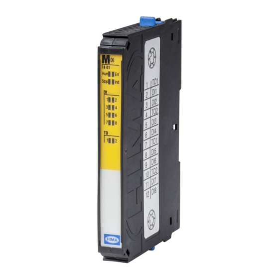
Page 15: Front View
M-DI 8 01 3 Product Description 3.4.4 Front View The following figure shows the front view of the module. Figure 3: Front View HI 800 661 E Rev. 1.00 Page 15 of 46... -
Page 16: Led Indicators
3 Product Description M-DI 8 01 3.4.5 LED Indicators The LEDs indicate the operating state of the module. The LEDs are classified as follows: Module status indicators I/O indicators When the supply voltage is switched on, a LED test is performed and all LEDs are briefly lit. Definition of Blinking Frequencies The following table defines the blinking frequencies of the LEDs: Name... -
Page 17: I/O Indicators
M-DI 8 01 3 Product Description 3.4.5.2 I/O Indicators The LEDs of the I/O indicators are labeled DI and TO. Color Status Description DI 1…8 Yellow The related input is active (energized). Blinking2 The related channel is faulty. The related input is inactive (de-energized). TO 1…2 Yellow The related output is active (energized). -
Page 18: Product Data
3 Product Description M-DI 8 01 Product Data General ≤ 5 %, Supply voltage 24 VDC, -15...+20 %, r PELV, SELV Max. supply voltage 30 VDC Current input 80 mA at 24 VDC Max. 90 mA Max. reaction time of the module 6.2 ms 0…+60 °C Ambient temperature... -
Page 19: Socket
M-DI 8 01 3 Product Description Socket Socket and module form together a functional unit. The module is connected to the system bus, the power supply and the field zone via socket. The field lines are connected to the socket's tension clamp terminals, see Figure 5. -
Page 20: Coding M-Di 8 01 Module And Socket
3 Product Description M-DI 8 01 3.6.2 Coding M-DI 8 01 Module and Socket To attach the module, the coding of the M-SO I/O 01 socket must be set as follows: Order Module coding (rear Position Coding socket view) Below Table 10: Module and Socket Coding 3.6.2.1 Configuring the Socket Coding... -
Page 21: Socket M-So I/O 01
M-DI 8 01 3 Product Description 3.6.3 Socket M-SO I/O 01 Universal socket for being equipped with different modules, see system manual HI 800 651 E. System Bus with Power Supply Field Terminals (Tension Clamp Terminals) Latch (Connection to the left Socket) Latch (Securing on DIN Rail) I/O Plug Figure 5:... -
Page 22: Terminal Assignment For The Field Terminals
3 Product Description M-DI 8 01 3.6.3.1 Terminal Assignment for the Field Terminals Terminal Signal Function TO1+ Pulsed Output 1 DI1+ Digital input 1 DI2+ Digital input 2 TO2+ Pulsed Output 2 DI3+ Digital input 3 DI4+ Digital input 4 TO1+ Pulsed Output 1 DI5+... -
Page 23: Start-Up
Start-Up This chapter describes how to install, configure and connect the module. For more information, refer to HIMatrix M45 system manual (HI 801 651 E). Mounting The module is plugged onto the corresponding socket. The socket is mounted on a 35 mm DIN rail. -
Page 24: Mounting And Removing The Modules And The Socket
4 Start-Up M-DI 8 01 Mounting and Removing the Modules and the Socket This chapter describes how to mount and remove the modules and sockets. When replacing modules, the sockets remain on the DIN rail. This saves additional wiring effort since all field lines are connected to the socket. -
Page 25: Figure 6: Sample Mounting A Socket
M-DI 8 01 4 Start-Up Setting and Lifting a Socket Connecting and Disconnecting Sockets Swiveling a Socket in and out Closing and Opening the Latch Figure 6: Sample Mounting a Socket HI 800 661 E Rev. 1.00 Page 25 of 46... -
Page 26: Mounting And Removing The Module
4 Start-Up M-DI 8 01 4.2.2 Mounting and Removing the Module This chapter describes how to mount and remove a module in the M45 system. Coding avoids installation of improper I/O modules. Mounting a module 1. Plug the module onto the socket, until the locking mechanism is engaged. Removing a module 1. -
Page 27: Line Control
M-DI 8 01 4 Start-Up Line Control Line control is used to detect short-circuits or open-circuits, e.g., on EMERGENCY STOP inputs complying with PL e in accordance with EN ISO 13849-1. The following line faults can be detected by using line control: ... -
Page 28: Configuring Line Control
4 Start-Up M-DI 8 01 4.3.2 Configuring Line Control Using SILworX, line control must be configured as follows: In the Module tab - Select Pulsed Output from the drop-down field Mode of Output 1. (Default setting: Supply) - Select Pulsed Output from the drop-down field Mode of Output 2. (Default setting: Supply) ... -
Page 29: Configuration With Silworx
M-DI 8 01 4 Start-Up Configuration with SILworX The module is configured in the Hardware Editor of the SILworX programming tool. Observe the following points when configuring the module: The inputs and outputs must be configured in accordance with the corresponding application. -
Page 30: Tab Module
4 Start-Up M-DI 8 01 4.4.1 Tab Module The Module tab contains the following system parameters: Name Description Enter these statuses and parameters directly in the Hardware Editor. Name Module name Mode of Output 1 Output 1 mode of operation, configurable to: ... -
Page 31: Tab M-Di 8 01_1: Channels
M-DI 8 01 4 Start-Up 4.4.2 Tab M-DI 8 01_1: Channels The M-DI 8 01_01: Channels tab contains the following parameters and statuses for each digital input. Global variables can be assigned to the statuses and parameters with -> and used in the user program. -
Page 32: Connection Variants
4 Start-Up M-DI 8 01 Connection Variants This chapter describes the correct wiring of the module in safety-related applications. The connection variants specified here are permitted. 4.5.1 Connection of Electromechanical Control Circuit Devices Electromechanical control circuit devices are connected as follows: TO 1 DI 1 TO 2... -
Page 33: Redundant Wiring
4 Start-Up 4.5.2 Redundant Wiring The redundant circuit of I/O modules is not supported in the HIMatrix M45 system. To improve availability, wiring inputs in parallel is permitted. The input signals must be evaluated in the user program. TO 1... -
Page 34: Connecting 3-Wire Proximity Switches
4 Start-Up M-DI 8 01 4.5.3 Connecting 3-Wire Proximity Switches Interconnect the module and the DI extension module M-LS 4 01 to connect 3-wire proximity switches. The DI extension module provides four additionally supplies and eight L- ports, see module M-LS 4 01 manual. TO 1 DI 1 DI 8... -
Page 35: Operation
M-DI 8 01 5 Operation Operation The module runs within the HIMatrix M45 system and does not require any specific monitoring. When operating the system, ensure that the air circulation is not obstructed. Handling Handling of the module and the HIMatrix M45 system during operation is not required. -
Page 36: Maintenance
Chapter 3.3. 6.2.2 Proof Test HIMatrix M45 modules must be subjected to a proof test in intervals of 10 years. For more information, refer to the safety manual (HI 800 653 E). Page 36 of 46... -
Page 37: Decommissioning
Decommissioning The decommissioning of the module is carried out after de-energization. Following steps are necessary: 1. Stop the HIMatrix M45 System. 2. Disconnect the system from the power supply. 3. Unplug the module from socket. HI 800 661 E Rev. 1.00... -
Page 38: Transport
8 Transport M-DI 8 01 Transport To avoid mechanical damage, HIMatrix M45 components must be transported in packaging. Always store HIMatrix components in their original product packaging. This packaging also provides protection against electrostatic discharge. Page 38 of 46 HI 800 661 E Rev. 1.00... -
Page 39: Disposal
9 Disposal Disposal Industrial customers are responsible for correctly disposing of decommissioned HIMatrix hardware. Upon request, a disposal agreement can be arranged with HIMA. All materials must be disposed of in an ecologically sound manner. HI 800 661 E Rev. 1.00... - Page 40 9 Disposal M-DI 8 01 Page 40 of 46 HI 800 661 E Rev. 1.00...
-
Page 41: Appendix
M-DI 8 01 Appendix Appendix Glossary Term Description Address resolution protocol: Network protocol for assigning the network addresses to hardware addresses Analog input Analog output Communication module Cyclic redundancy check Digital input Digital output Electromagnetic compatibility European norm Electrostatic discharge Fieldbus Function block diagrams Fault tolerance time... -
Page 42: Index Of Figures
Appendix M-DI 8 01 Index of Figures Figure 1: Sample Type Label Figure 2: Block Diagram Figure 3: Front View Figure 4: Sample Coding of Module and Socket Figure 5: Socket M-SO I/O 01 Figure 6: Sample Mounting a Socket Figure 7: Sample Mounting and Removing a Module Figure 8:... -
Page 43: Index Of Tables
M-DI 8 01 Appendix Index of Tables Table 1: Additional Relevant Documents Table 2: Environmental Requirements Table 3: Module Inputs and Outputs Table 4: Blinking Frequencies of LEDs Table 5: Module Status Indicators Table 6: I/O LEDs Table 7: Product Data Table 8: Specifications for Digital Inputs Table 9:... -
Page 44: Index
Appendix M-DI 8 01 Index block diagram ..........14 front view ........... 15 diagnosis ........... 35 safety function ..........10 fault reaction specifications ..........18 digital inputs ........... 10 Page 44 of 46 HI 800 661 E Rev. 1.00... - Page 46 HIMA Paul Hildebrandt GmbH + Co KG P.O. Box 1261 68777 Brühl, Germany Phone: +49 6202 709-0 Fax: +49 6202 709-107 E-mail: info@hima.com Internet: www.hima.com (1343)
Need help?
Do you have a question about the HIMatrix M45 and is the answer not in the manual?
Questions and answers