
Subscribe to Our Youtube Channel
Related Manuals for HIMA HIMatrix M45


Summary of Contents for HIMA HIMatrix M45
- Page 1 HIMatrix Safety-Related Controller Manual M-CPU 01 HIMA Paul Hildebrandt GmbH + Co KG Industrial Automation Rev. 1.00 HI 800 655 E...
- Page 2 All HIMA products mentioned in this manual are protected by the HIMA trade-mark. Unless noted otherwise, this also applies to other manufacturers and their respective products referred to herein. ® ® ® ® ® HIMax , HIMatrix , SILworX , XMR...
-
Page 3: Table Of Contents
M-CPU 01 Table of Contents Table of Contents Introduction Structure and Use of this Manual Target Audience Formatting Conventions 1.3.1 Safety Notes 1.3.2 Operating Tips Safety Intended Use 2.1.1 Environmental Requirements 2.1.2 ESD Protective Measures Residual Risk Safety Precautions Emergency Information Product Description Safety Function 3.1.1... - Page 4 Table of Contents M-CPU 01 Start-up Mounting Mounting and Removing the Modules and the Socket 4.2.1 Mounting a Socket 4.2.2 Mounting and Removing the Modules Configuration 4.3.1 Tab Module 4.3.2 Tab Routings 4.3.3 Tab Ethernet Switch 4.3.4 Tab VLAN (Port-Based VLAN) 4.3.5 Tab LLDP 4.3.6...
-
Page 5: Introduction
SILworX. Structure and Use of this Manual The content of this manual is part of the hardware description of the HIMatrix M45 programmable electronic system. This manual is organized in the following main chapters: ... -
Page 6: Formatting Conventions
1 Introduction M-CPU 01 Formatting Conventions To ensure improved readability and comprehensibility, the following fonts are used in this document: Bold To highlight important parts. Names of buttons, menu functions and tabs that can be clicked and used in the programming tool. Italics For parameters and system variables Courier... -
Page 7: Operating Tips
M-CPU 01 1 Introduction 1.3.2 Operating Tips Additional information is structured as presented in the following example: The text corresponding to the additional information is located here. Useful tips and tricks appear as follows: The tip text is located here. HI 800 655 E Rev. -
Page 8: Safety
2 Safety M-CPU 01 Safety All safety information, notes and instructions specified in this document must be strictly observed. The product may only be used if all guidelines and safety instructions are adhered to. The product is operated with SELV or PELV. No imminent risk results from the product itself. The use in Ex-Zone is permitted if additional measures are taken. -
Page 9: Residual Risk
Observe all local safety requirements and use the protective equipment required on site. Emergency Information A HIMatrix M45 system is a part of the safety equipment of a plant. If a device or a module fails, the system enters the safe state. -
Page 10: Product Description
M-CPU 01 Product Description The M-CPU 01 processor module is the central component of the HIMatrix M45 controller. The module is always the leftmost HIMatrix M45 module on the DIN rail. The M-CPU 01 module is used to store the operating system and the user program. The module executes all central functions, including communication with the PADT and other systems. -
Page 11: Type Label
M-CPU 01 3 Product Description Type Label The type plate contains the following details: Product name Mark of conformity Bar code (2D code) Part number (Part-No.) Hardware revision index (HW-Rev.) Operating system revision index (OS-Rev.) ... -
Page 12: Structure
3 Product Description M-CPU 01 Structure This chapter describes the layout and function of the module, and its communication via safeethernet. 3.4.1 Block Diagram Watchdog Non-Volatile Memory System Bus Ethernet Switch Power Supply 1oo2D Processor System Voltage Monitoring System Bus Switch Figure 2: Block Diagram Page 12 of 38... -
Page 13: Front View
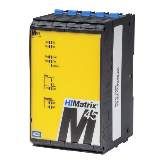
M-CPU 01 3 Product Description 3.4.2 Front view Figure 3: Front View M-CPU 01 HI 800 655 E Rev. 1.00 Page 13 of 38... -
Page 14: Led Indicators
3 Product Description M-CPU 01 3.4.3 LED indicators The LEDs indicate the operating state of the module. The LEDs are classified as follows: System LEDs Program LEDs User and system bus LEDs Communication LEDs When the supply voltage is switched on, a LED test is performed and all LEDs are briefly lit. Definition of Blinking Frequencies The following table defines the blinking frequencies of the LEDs: Name... -
Page 15: Program Light Emitting Diodes
M-CPU 01 3 Product Description 3.4.3.2 Program Light Emitting Diodes The LEDs signal the following states: Color Status Description The controller is being loaded with a new configuration. Prog Yellow Emergency loader active. A new operating system is being loaded. ... -
Page 16: Ethernet Indicators
Cycle time monitoring (watchdog) Communication with other systems For a description of the operating system functions and the variables used to configure the systems and all modules, refer to the HIMatrix M45 system manual (HI 800 651 E). 3.4.5 User Program The user program is created using the SILworX programming tool. -
Page 17: Connections For Ethernet Communication
Network Ports (UDP Ports) in Use 3.4.8 Monitoring the Operating Voltage The M-CPU 01 processor module monitors the 24 VDC operating voltage of the HIMatrix M45; reactions occur in accordance with the listed levels: Voltage level Reaction of the CPU 18...28.8 V... -
Page 18: Product Data
3 Product Description M-CPU 01 Product Data General 5 %, Operating voltage 24 VDC, -15...+20 %, r from a power supply unit with safe insulation in accordance with IEC 61131-2 Maximum supply voltage 30 V Operating data 3.3 VDC / 1.5 A 5 VDC / 0.1 A Microprocessor PowerPC... -
Page 19: Socket M-So Cpu 01
Table 12: Certificates Further safety standards and application standards are specified in the certificate. The certificate and the EC type test certificate are available on the HIMA website at www.hima.com. HI 800 655 E Rev. 1.00 Page 19 of 38... -
Page 20: Start-Up
The module is mounted on a 35 mm DIN rail using the corresponding M-SO CPU 01 socket. When installing the HIMatrix M45 system, the socket must be mounted as the first one on the left side of the DIN rail. The remaining sockets must be mounted from the right side. -
Page 21: Figure 5: Sample Mounting A Socket
M-CPU 01 4 Start-up Setting and Lifting a Socket Connecting and Disconnecting Sockets Swiveling a Socket in and out Closing and Opening the Latch Figure 5: Sample Mounting a Socket HI 800 655 E Rev. 1.00 Page 21 of 38... -
Page 22: Mounting And Removing The Modules
4 Start-up M-CPU 01 4.2.2 Mounting and Removing the Modules This chapter describes how to mount and remove the processor module in the M45 system. Mounting a module 1. Plug the module - without jamming is - onto the socket, until the locking mechanism is engaged. -
Page 23: Tab Module
M-CPU 01 4 Start-up 4.3.1 Tab Module The Module tab contains the following parameters: Parameter Description Name Module name Activated: Use CPU load limit from the Max. µP Budget for HH Activate Max. µP Budget for HH Protocol Protocol [%] field. ... -
Page 24: Table 13: Configuration Parameters, Module Tab
4 Start-up M-CPU 01 Parameter Description MAC Learning MAC Learning and ARP Aging Time are used to set how quick the Ethernet switch should learn the MAC address. The following settings are possible: Conservative (recommended): If the ARP cache already contains MAC addresses of communication partners, these are locked and cannot be replaced by other MAC addresses for at least 1 ARP Aging Time and a maximum of 2 ARP Aging Time periods. -
Page 25: Tab Routings
M-CPU 01 4 Start-up 4.3.2 Tab Routings The Routings tab contains the routing table. This table is empty if the module is new. A maximum of 8 routing entries are possible. Parameter Description Name Denomination of the routing settings IP Address Target IP address of the communication partner (with direct host rout- ing) or network address (with subnet routing). -
Page 26: Tab Vlan (Port-Based Vlan)
4 Start-up M-CPU 01 4.3.4 Tab VLAN (Port-Based VLAN) For configuring the use of port-based VLAN. Should VLAN be supported, port-based VLAN should be off to enable each port to communicate with the other switch ports. For each switch port, the user can define which other switch ports received Ethernet frames may be sent to. -
Page 27: Operation
M-CPU 01 5 Operation Operation The module runs within the HIMatrix M45 system and does not require any specific monitoring. When operating the system, ensure that the air circulation is not obstructed. Handling Handling of the module and the HIMatrix M45 system during operation is not required. -
Page 28: Maintenance
Loading the Operating System HIMA is continuously improving the operating system of the modules. HIMA recommends to use system downtimes to load a current version of the operating system into module. Refer to the release notes to check the consequences of the operation system version on the system! The operating system can be loaded into the module using SILworX. -
Page 29: Proof Test
6 Maintenance 6.2.2 Proof Test HIMatrix M45 modules must be subjected to a proof test in intervals of 10 years. For more information, refer to the safety manual (HI 800 653 E). HI 800 655 E Rev. 1.00 Page 29 of 38... -
Page 30: Decommissioning
M-CPU 01 Decommissioning The decommissioning of the module is carried out after de-energization. Following steps are necessary: 1. Stop the HIMatrix M45 System. 2. Disconnect the system from the power supply. 3. Unplug the module from socket. Page 30 of 38... -
Page 31: Transport
M-CPU 01 8 Transport Transport To avoid mechanical damage, HIMatrix components must be transported in packaging. Always store HIMatrix components in their original product packaging. This packaging also provides protection against electrostatic discharge. Note that the product packaging alone is not suitable for transport. -
Page 32: Disposal
M-CPU 01 Disposal Industrial customers are responsible for correctly disposing of decommissioned HIMatrix hardware. Upon request, a disposal agreement can be arranged with HIMA. All materials must be disposed of in an ecologically sound manner. Page 32 of 38 HI 800 655 E Rev. 1.00... -
Page 33: Appendix
M-CPU 01 Appendix Appendix Glossary Term Description Address resolution protocol: Network protocol for assigning the network addresses to hardware addresses Analog input Analog output Communication module Cyclic redundancy check Digital input Digital output Electromagnetic compatibility European norm Electrostatic discharge Fieldbus Function block diagrams Fault tolerance time ICMP... -
Page 34: Index Of Figures
Appendix M-CPU 01 Index of Figures Figure 1: Sample Type Label Figure 2: Block Diagram Figure 3: Front View M-CPU 01 Figure 4: Socket M-SO CPU 01 Figure 5: Sample Mounting a Socket Figure 6: Mounting a Module onto the Socket Page 34 of 38 HI 800 655 E Rev. -
Page 35: Index Of Tables
M-CPU 01 Appendix Index of Tables Table 1: Additional Relevant Documents Table 2: Environmental Requirements Table 3: Blinking Frequencies of LEDs Table 4: Module Status Indicators Table 5: Program Light Emitting Diodes Table 6: User and System Bus LEDs Table 7: Ethernet Indicators Table 8: Connections for Fieldbus Communication... -
Page 36: Index
Appendix M-CPU 01 Index block diagram..........12 mounting............. 20 diagnosis.............27 M-SO CPU 01 socket ......... 19 Ethernet indicators ........16 program LEDs ..........15 system bus indicators......15 safety function ..........10 Ethernet interfaces........16 specifications..........18 front view.............13 Ethernet interfaces........17 module status indicators ......14 Page 36 of 38 HI 800 655 E Rev. - Page 38 HIMA Paul Hildebrandt GmbH + Co KG P.O. Box 1261 68777 Brühl, Germany Phone: +49 6202 709-0 Fax: +49 6202 709-107 E-mail: info@hima.com Internet: www.hima.com (1343)
Need help?
Do you have a question about the HIMatrix M45 and is the answer not in the manual?
Questions and answers